
Subscribe to Our Youtube Channel
Related Manuals for ADLINK Technology cPCI-3620 Series


Summary of Contents for ADLINK Technology cPCI-3620 Series
- Page 1 Series ® Low-Power 3U CompactPCI ® Quad-Core Intel Atom™ Processor Blade User’s Manual Manual Rev.: 1.00 Revision Date: February 16, 2016 Part No: 50-15098-2000 Advance Technologies; Automate the World.
-
Page 2: Revision History
Revision History Revision Release Date Description of Change(s) 1.00 16/02/2016 Initial release Revision History... -
Page 3: Preface
Preface Copyright 2016 ADLINK Technology Inc. This document contains proprietary information protected by copy- right. All rights are reserved. No part of this manual may be repro- duced by any mechanical, electronic, or other means in any form without prior written permission of the manufacturer. - Page 4 Conventions Take note of the following conventions used throughout this manual to make sure that users perform certain tasks and instructions properly. Additional information, aids, and tips that help users perform tasks. NOTE: NOTE: Information to prevent minor physical injury, component dam- age, data loss, and/or program corruption when trying to com- plete a task.
-
Page 5: Table Of Contents
3 Functional Description ............ 17 Processors................. 17 PMC/XMC................19 Intel® Virtualization Technology ........19 Intel® AES New Instructions..........19 Battery ................20 4 Board Interfaces ............... 21 cPCI-3620 Series Board Layout ........21 cPCI-3620 Blade Assembly Layout ........22 Table of Contents... - Page 6 Blade Assembly Layout......... 23 cPCI-3620T Blade Assembly Layout ......... 24 cPCI-3620N Blade Assembly Layout......... 25 cPCI-3620 Series Faceplate ..........26 cPCI-R3610(T) RTM Board Layout........29 cPCI-R3610(T) RTM Faceplate ......... 30 Connector Pin Assignments..........31 4.10 Jumper Settings ..............47 5 Getting Started ..............
- Page 7 cPCI-3620 8.3.7 Network Stack Configuration ......... 75 8.3.8 CSM Configuration ............76 8.3.9 USB Configuration ............77 Chipset Configuration ............78 8.4.1 North Bridge..............78 8.4.2 South Bridge ..............80 Security................82 Boot Settings ..............83 Save & Exit Menu .............. 84 Important Safety Instructions ..........
- Page 8 This page intentionally left blank. viii Table of Contents...
-
Page 9: List Of Figures
Figure 2-3: cPCI-3620T Daughter Board Functional Block Diagram11 Figure 2-4: cPCI-R3610 RTM Functional Block Diagram ....12 Figure 4-1: cPCI-3620 Series Board Layout ........21 Figure 4-2: cPCI-3620 Blade Assembly Layout ....... 22 Figure 4-3: cPCI-3620D Blade Assembly Layout......23 Figure 4-4: cPCI-3620T Blade Assembly Layout ...... - Page 10 This page intentionally left blank. List of Figures...
-
Page 11: List Of Tables
cPCI-3620 List of Tables Table 2-1: cPCI-3620 Processor Blade Specifications ..... 7 Table 2-2: cPCI-R3610(T) RTM Specifications......... 9 Table 2-3: cPCI-3620 I/O Connectivity ........... 13 Table 4-1: cPCI-3620 Faceplate System LED Descriptions ... 28 Table 4-2: USB 2.0 Pin Definition ........... 31 Table 4-3: VGA Pin Definition ............ - Page 12 This page intentionally left blank. List of Tables...
-
Page 13: Introduction
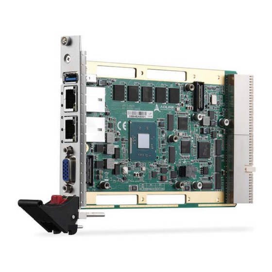
DDR3L-1333 ECC. Available in single-slot (4HP) or dual-slot (8HP) width form factors, the cPCI-3620 Series utilizes various daughter boards to provide a broad range of I/O functionality. Faceplate I/O on the single-slot (4HP) version includes 1x USB 3.0, 2x RJ-45 GbE and 1x VGA port (common to all versions). -
Page 14: Features
1.2 Features 3U CompactPCI blade in 4HP or 8HP width form factor ® Intel Atom™ Processor E3845 SoC (4 cores, 2M L3 cache, 1.9 GHz) Graphics and memory controllers integrated in SoC Compatible with PICMG 2.0 CompactPCI R3.0 and PICMG 2.1 Hot Swap R2.0 4GB single channel DDR3L-1333 soldered ECC SDRAM 32-bit, 33/66MHz CompactPCI interface, universal V(I/O) -
Page 15: Model Number Decoder
cPCI-3620 Model Number Decoder Blades cPCI-3620D E3845 (A) Configuration Code Blank = Single-slot width, 1x VGA, 1x USB 3.0, 2x GbE D = Dual-slot width, 1x VGA, 1x USB 3.0, 2x GbE on layer 1; 2x USB 2.0, 1x COM (RS-232/422/485), 1x PS/2 KB/MS, Line-in, Line-out and 2.5"... - Page 16 RTMs cPCI- R3610T (A) Model Code Blank = Dual-slot width, 50mm depth 3U RTM with 2x COM, 1x USB 2.0, 1x SATA 3Gb/s, 1x VGA, 2x GbE T = Dual-slot width, 80mm depth 3U RTM with 2 x COM, 1x USB 2.0, 1x SATA 3Gb/s, 1x VGA, 2x GbE 2x GbE, 1x VGA and 1x SATA signals on RTM are switched from faceplate of blade.
-
Page 17: Package Contents
Please obtain authorization before returning any product to ADLINK. The packing contents of cPCI-3620 Series non-standard configurations will vary depending on customer requests. Processor Blade... - Page 18 This page intentionally left blank. Introduction...
-
Page 19: Specifications
cPCI-3620 Specifications 2.1 cPCI-3620 Processor Blade Specifications ® ® ® • PICMG 2.0 CompactPCI Rev. 3.0 CompactPCI ® • PICMG 2.1 Hot Swap Specification Rev. 2.0 Standards ® Mechanical • Standard 3U CompactPCI • Board size: 100mm x 160mm • Single slot (4HP, 20.32mm); Dual slot (8HP, 40.64mm) ®... - Page 20 Faceplate I/O 4HP (cPCI-3620) • 1x USB 3.0 port • 2x 10/100/1000BASE-T Ethernet ports • 1x VGA port 4HP (cPCI-3620N) • LEDs only (Power, HDD, WDT, GP, GbE), no I/O 8HP (cPCI-3620D) • 1x USB 3.0 ports • 2x 10/100/1000BASE-T Ethernet ports •...
-
Page 21: Cpci-R3610(T) Rtm Specifications
cPCI-3620 1. The storage device limits the operational vibration tolerance. When the application requires higher specification for anti-vibration, it is recommended to use a flash storage device. 2. ADLINK-certified thermal design. The thermal performance is depen- dent on the chassis cooling design. Sufficient forced air-flow is required. Temperature limits of optional mass storage devices may also affect the thermal specification. -
Page 22: Block Diagrams
2.3 Block Diagrams cPCI-3620 Blade Front Panel GbE2 GbE1 Intel Intel I210 I210 SATA0 PCIe x1 PCIe x1 Battery PCIe to PCI Dual/Quad-Core USB 2.0 PCIe x1 Bridge Gen Intel® Atom™ COM x2 BIOS1 BIOS2 KB/MS SMBus 2x USB 2.0 PCIe x1 DB-3610L2 B2B #1... - Page 23 cPCI-3620 cPCI-3620D Daughter Board USB x2 Line-in, Line-out Codec SATA1 Conn. 2.5” Drive PS/2 KB/MS Figure 2-2: cPCI-3620D Daughter Board Functional Block Diagram cPCI-3620T Daughter Board GbE x2 via M12 PCIe x1 82574 x2 PCIe SW SATA0 2.5” Drive Repeater Conn.
-
Page 24: Figure 2-4: Cpci-R3610 Rtm Functional Block Diagram
cPCI-R3610(T) RTM COM Header x2 GbE x2 USB 2.0 x2 2.5” SSD/HDD Figure 2-4: cPCI-R3610 RTM Functional Block Diagram Specifications... -
Page 25: I/O Connectivity Table
cPCI-3620 2.4 I/O Connectivity Table cPCI-3620 (4HP) cPCI-362D (8HP) cPCI-3620T (8HP) Function Faceplate Onboard Faceplate Onboard Faceplate Onboard Gigabit Ethernet Y x2 Y x2 Y x2 Y (DB-9) Y (DB-9) USB 3.0 USB 2.0 Y x2 Y (for 2.5” Y (for 2.5” Serial ATA drive) drive) -
Page 26: Power Requirements
2.5 Power Requirements In order to guarantee a stable functionality of the system, it is rec- ommended to provide more power than the system requires. An industrial power supply unit should be able to provide at least twice as much power as the entire system requires of each voltage. -
Page 27: Power Consumption
Power Consumption This section provides information on the power consumption of ® cPCI-3620 Series when using the Intel Atom™ processors with 4GB DDR3L-1333 ECC soldered memory and a 2.5” SATA SSD. The cPCI-3620 is powered by 5V. Power consumption at 100% CPU usage was measured using the Intel Thermal Analysis Tool (TAT). - Page 28 This page intentionally left blank. Specifications...
-
Page 29: Functional Description
Functional Description The following sections describe the cPCI-3620 Series features and functions. 3.1 Processors ® The cPCI-3620 Series supports the Intel Atom™ processor E3845 which utilize 22nm process technology with 3-D Tri-Gate transistor to deliver significant improvement in computational per- formance and energy-efficiency in intelligent systems. -
Page 30: Supported Technologies
Supported Technologies Features Atom™ E3845 ® Intel vPro Technology ® Intel Hyper-Threading Technology ® Intel Virtualization Technology ® Intel Virtualization Technology for Directed I/O ® Intel 64 Architecture ® Intel HD Audio Technology ® Intel Data Protection Technology – ® Intel AES New Instructions ®... -
Page 31: Pmc/Xmc
cPCI-3620 Graphics ® The graphics is integrated in the processor and based on Intel HD Graphics 4000 technology, enabling substantial gains in per- formance and lower power consumption. DirectX 11 support OpenGL 4.0 support Graphics Base Frequency: 542 MHz Graphics Max Dynamic Frequency: 792 MHz Full HD video playback Maximum resolution of 2560x1600@60Hz 3.2 PMC/XMC... -
Page 32: Battery
secure business-critical data, and AES is the most widely used standard when protecting network traffic, personal data, and cor- porate IT infrastructures. AES is a widely-deployed encryption standard when protecting network traffic, personal data, and cor- ® porate IT infrastructures; and Intel AES-NI can be used to accel- erate the AES encryption. -
Page 33: Board Interfaces
4.1 cPCI-3620 Series Board Layout LAN1 LAN2 Solder Side ® LAN1 Intel Atom™ Processor Ethernet RJ-45 connector LAN2 CompactPCI connector J1 Ethernet RJ-45 connector CompactPCI connector J2 DB-15 female VGA connector USB 3.0 port Reset Button Figure 4-1: cPCI-3620 Series Board Layout Board Interfaces... -
Page 34: Cpci-3620 Blade Assembly Layout
4.2 cPCI-3620 Blade Assembly Layout This section describes the final assembly layout of the single slot cPCI-3620 blade with the storage daughter board. Heatsink Battery Storage Daughter Board Figure 4-2: cPCI-3620 Blade Assembly Layout Battery CompactPCI connector J1 CompactPCI connector J2 The onboard SSD on the storage daughter board is optional. -
Page 35: Cpci-3620D Blade Assembly Layout
cPCI-3620 4.3 cPCI-3620D Blade Assembly Layout The dual-slot width cPCI-3620D is comprised of the cPCI-3620 single-slot main board and the cPCI-3620D daughter board to expand I/O connectivity with PS/2, COM, 2x USB, Line-in, and Line-out ports. SATA USB1 USB2 PS/2 Audio1 Audio2 cPCI-3620D Daughter Board... -
Page 36: Cpci-3620T Blade Assembly Layout
4.4 cPCI-3620T Blade Assembly Layout The dual-slot width cPCI-3620T is comprised of the cPCI-3620 single-slot main board and the cPCI-3620T Daughter Board to expand I/O connectivity with COM, 2x GbE with M12 MIL-STD connectors SATA1 2.5” SATA Drive COM1 cPCI-3620T Daughter Board COM1 M12 MIL-STD connectors... -
Page 37: Cpci-3620N Blade Assembly Layout
cPCI-3620 4.5 cPCI-3620N Blade Assembly Layout The single slot cPCI-3620N provides LED indicators only with no I/ O on the faceplate LAN1 LEDs LAN2 LEDs Figure 4-5: cPCI-3620N Blade Assembly Layout Board Interfaces... -
Page 38: Cpci-3620 Series Faceplate
4.6 cPCI-3620 Series Faceplate USB 3.0 LAN1 LAN2 cPCI-3620 Reset Thermal GPIO Power cPCI-3620D PS/2 USB 2.0 COM1 KB/MS Line out Line in Reset Thermal GPIO Power LAN2 LAN1 cPCI-3620N 100M 100M 1000M 1000M Link Link Reset Thermal GPIO Power... -
Page 39: Figure 4-7: Cpci-3620T/S Faceplate Layout
cPCI-3620 cPCI-3620T GbE1 GbE2 COM1 Reset Thermal GPIO Power cPCI-3620S XMC IO Reset Thermal GPIO Power Figure 4-7: cPCI-3620T, cPCI-3620S Faceplate Layout Board Interfaces... -
Page 40: Table 4-1: Cpci-3620 Faceplate System Led Descriptions
System LEDs Color Condition Indication System is off Power Green/ Green Post OK No Watchdog event Orange Blinking Watchdog event alert No SATA drive activity Blue Data read/write in process for CF/CFast/ Blinking SATA HDD Board temperature is below 85°C Thermal Board temperature equals or exceeds 85°C... -
Page 41: Cpci-R3610(T) Rtm Board Layout
cPCI-3620 4.7 cPCI-R3610(T) RTM Board Layout SATA1 SATA2 COM2 USB 5 SW1-4 COM3 VGA1 SW5-8 COM2 LAN1/2 RS-232/422/485 port Dual Ethernet ports COM3 VGA1 RS-232/422/485 port VGA port SATA1 SATA port switched from USB 2.0 port front by BIOS (SATA2 not connected) SW1-8 CompactPCI connector Switches... -
Page 42: Cpci-R3610(T) Rtm Faceplate
4.8 cPCI-R3610(T) RTM Faceplate COM3 COM2 GbE x2 Figure 4-9: cPCI-R3610(T) RTM Faceplate Board Interfaces... -
Page 43: Connector Pin Assignments
cPCI-3620 4.9 Connector Pin Assignments USB 2.0 Connectors Pin # Signal Name UV0- UV0+ Table 4-2: USB 2.0 Pin Definition USB 3.0 Connectors Pin # Signal Name USB3.0_P5VA USB2_CMAN USB2_CMAP USB3A_CMRXN USB3A_CMRXP USB3A_CMTXN USB3A_CMTXP Board Interfaces... -
Page 44: Table 4-3: Vga Pin Definition
DB-15 VGA Connector Signal Name Pin # Pin # Signal Name Green Blue N.C. +5V. N.C. CRTDATA HSYNC VSYNC CRTCLK Table 4-3: VGA Pin Definition PS/2 Keyboard/Mouse Connector Pin # Signal Function KBDATA Keyboard Data MSDATA Mouse Data Ground Power KBCLK Keyboard Clock MSCLK... -
Page 45: Table 4-5: Rj-45 Gbe Pin Definitions
cPCI-3620 RJ-45 Gigabit Ethernet Connectors 10BASE-T/ Pin # 1000BASE-T 100BASE-TX LAN_TX0+ LAN_TX0- LAN_TX1+ — LAN_TX2+ — LAN_TX2- LAN_TX1- — LAN_TX3+ — LAN_TX3- Table 4-5: RJ-45 GbE Pin Definitions Speed Activity Speed LED Activity LED Status (Green/Amber) (Yellow) Network link is not established or system powered off Link 10 Mbps... -
Page 46: Table 4-7: Rj-45 Gbe Pin Definitions
M12 Gigabit Ethernet Connectors Pin # Signal Table 4-7: RJ-45 GbE Pin Definitions cPCI-3620D/T Serial Ports COM1 Connector (DB-9) Pin # RS-232 RS-422 RS-485(+) DCD-L TXD- TXD- TXD+ TXD+ RXD+ — DTR-L RXD- — DSR-L — — RTS-L — — CTS-L —... -
Page 47: Table 4-9: Cpci-3620D Com1 Mode Selection Switch Settings
cPCI-3620 cPCI-3620D COM1 Mode Selection Switches (SW1~SW4) These switches set the cPCI-3620D COM1 to RS-232 full modem, RS-422, RS-485, or RS-485+ half-duplex mode. Switches SW1~SW4 are located on the top edge of the DB-3610L2 board. RS-232 full modem is set by default. Mode RS-232 RS-422... - Page 48 cPCI-3620T COM1 Mode Selection Switch (SW1) These switches set the cPCI-3620T COM1 to RS-232 full modem, RS-422 or RS-485. Switch SW1 is located next to the COM1 connector on the DB-3620L2 board. RS-232 full modem is set by default. Mode RS-232 RS-422 RS-485...
-
Page 49: Table 4-10: Serial Ata Connector On Db-3610L2 Pin Definition
cPCI-3620 Serial ATA Connector on DB-3610L2 Pin # Signal Signal Power P13~P15 Table 4-10: Serial ATA Connector on DB-3610L2 Pin Definition Board Interfaces... -
Page 50: Table 4-11: Pmc Connector Pin Definitions
PMC Connector on DB-3UMC (JN1/2) Pin# JN1 Signal JN2 Signal PMC_TCK P12V N12V PMC_TRST-L PMC_TMS PCIX_INTA-L NC (PMC_TDO) PCIX_INTB-L PMC_TDI PCIX_INTC-L PMC_MOD-L1 PCIX_INTD-L PMC_MOD-L2 P3V3_PMCAUX P3V3 CLK66_PCIX_PMC PMC_RST-L PMC_MOD-L3 P3V3 PCIX_GNT-L0 PMC_MOD-L4 PCIX_REQ-L0 PMC_PME-L PMC_VIO PCIX_AD30 PCIX_AD31 PCIX_AD29 PCIX_AD28 PCIX_AD27 PCIX_AD26 PCIX_AD25 PCIX_AD24... - Page 51 cPCI-3620 Pin# JN1 Signal JN2 Signal PCIX_FRAME-L PCIX_TRDY-L PCIX_IRDY-L P3V3 PCIX_DEVSEL-L PCIX_STOP-L PCIX_PCIXCAP PCIX_PERR-L PCIX_LOCK-L P3V3 PCIX_SERR-L PCIX_PAR PCIX_CBE-L1 PMC_VIO PCIX_AD14 PCIX_AD15 PCIX_AD13 PCIX_AD12 PCIX_M66EN PCIX_AD11 PCIX_AD10 PCIX_AD9 PCIX_AD8 P3V3 PCIX_AD7 PCIX_CBE-L0 PCIX_AD6 P3V3 PCIX_AD5 PCIX_AD4 PMC_VIO PCIX_AD3 PCIX_AD2 PCIX_AD1 PCIX_AD0 PCIX_ACK64-L P3V3...
-
Page 52: Table 4-12: Xmc Connector Pin Definition
XMC Connector on DB-3UMC (JN3) Pin# 3.3V VPWR Not used PCIE_RST-L 3.3V VPWR Not used Not used 3.3V VPWR Not used +12V 3.3V VPWR Not used -12V Not used VPWR Not used Not used VPWR Not used 3.3V VPWR Not used Not used VPWR Not used... -
Page 53: Table 4-13: Compactpci J1 Connector Pin Definition
cPCI-3620 CompactPCI J1 Connector REQ64# ENUM# CPCI_AD1 CPCI_VIO CPCI_AD0 ACK64# CPCI_AD4 CPCI_AD3 CPCI_AD2 CPCI_AD7 CPCI_AD6 CPCI_AD5 CPCI_AD9 CPCI_AD8 CPCI_M66EN CPCI_CBE-L0 GND CPCI_AD12 CPCI_AD11 CPCI_AD10 CPCI_AD15 CPCI_AD14 CPCI_AD13 GND CPCI_SERR-L CPCI_PAR CPCI_CBE-L1 GND CPCI_PERR-L GND GND CPCI_DEVSEL-L CPCI_STOP-L CPCI_LOCK-L GND CPCI_FRAME-L CPCI_IRDY-L CPCI_BDSEL# CPCI_TRDY-L GND 12-14 CPCI_AD18... -
Page 54: Table 4-14: Compactpci J2 Connector Pin Definition
CompactPCI J2 Connector CLK6 LAN1_TXDP0 LAN1_TXDN0 CLK5 LAN1_TXDP2 R_LAN2_1000-L GND LAN1_TXDN2 LAN1_TXDP1 LAN1_TXDN1 GND R_LAN2_100-L LAN1_TXDP3 LAN1_TXDN3 +3.3V GND R_LAN2_LINK/ACT-L PRSTJ REQ6# GNT6# GPIO0 R_LAN1_100-L USB6-P R_LAN1_1000-L GND RGB_BLUE R_LAN1_LINK/ACT-L USB6-N REQ5# GNT5# GPIO1 USB_6_OC# USB_5_OC# SATA_TX-N1 COM2_RI# LAN2_TXDP0 SATA_TX-P1 COM2_DTR# COM2_CTS# GPIO2 LAN2_TXDN0... -
Page 55: Table 4-15: Cpci-R3610(T) Serial Port Pin Header Definition
cPCI-3620 cPCI-R3610(T) RTM Serial Ports Serial Port Pin Headers (COM2/3) Pin # RS-232 RS-422 RS-485(+) DCD-L TXD- TXD- DSR-L — — TXD+ TXD+ RTS-L — — RXD+ — CTS-L — — DTR-L RXD- — RI-L — — — — — Table 4-15: cPCI-R3610(T) Serial Port Pin Header Definition Serial Port DB-9 Connectors (COM2/3) Pin #... -
Page 56: Table 4-17: Com2 Mode Selection Switch Settings
COM2 Mode Selection Switches on RTM (SW1~SW4) These switches on the RTM select COM2 to be RS-232 full modem, RS-422, RS-485, or RS-485+ half-duplex mode. RS-232 full modem is set by default. See “cPCI-R3610(T) RTM Board Layout” on page 29 for switch locations. Mode RS-232 RS-422... -
Page 57: Table 4-18: Com3 Mode Selection Switch Settings
cPCI-3620 COM3 Mode Selection Switches on RTM (SW5~SW8) These switches on the RTM select COM3 to be RS-232 full modem, RS-422, RS-485, or RS-485+ half-duplex mode. RS-232 full modem is set by default. See “cPCI-R3610(T) RTM Board Layout” on page 29 for switch locations. Mode RS-232 RS-422... -
Page 58: Table 4-19: Serial Ata Connector On Rtm
Serial ATA Connectors on RTM Pin # Signal Table 4-19: Serial ATA Connector on RTM Board Interfaces... -
Page 59: Jumper Settings
cPCI-3620 4.10 Jumper Settings XMC VPWR Select Jumper on DB-3UMC (JPX1) This jumper is located on the DB-3UMC board near JN1/2 and selects the XMC VPWR setting. 5V is set by default. Mode Connection JPX1 +5V (Default) 1 – 2 +12V 2 –... - Page 60 This page intentionally left blank. Board Interfaces...
-
Page 61: Getting Started
Processor blade installation to chassis RTM installation to chassis 5.1 CPU and Heatsink The cPCI-3620 Series come with CPU and heatsink pre-installed. Removal of heatsink/CPU by users is not recommended. Please contact your ADLINK service representative for assistance. Getting Started... -
Page 62: Sata Drive Installation
5.2 SATA Drive Installation The cPCI-3620D/T 2-slot versions provide space to install a slim type 2.5" Serial-ATA storage drive. SATA Drive Installing a - cPCI-3620D/T 1. A 2.5" SATA drive can be assembled in the location marked as below. 2. Prepare a 2.5" SATA drive and locate the brackets and screws in the accessory kit. - Page 63 cPCI-3620 3. Screw the brackets to the 2.5" SATA drive with the four with M3 screws provided. 4. Align the drive assembly with the cPCI-3620D/T and insert it into the onboard SATA connector until it is prop- erly seated. Getting Started...
-
Page 64: Pmc/Xmc Card Installation
5. Secure the hard drive assembly to the cPCI-3620D/T with four M2.5 screws provided. 5.3 PMC/XMC Card Installation The cPCI-3620S provides one PMC/XMC slot designed to support 3.3V or 5V V(I/O) (default 3.3V) and 5V or 12V VPWR (default 5V). Before you install the PMC/XMC card on the cPCI-3620S, please make sure that the PMC V(I/O) jumper JPX2 and XMC VPWR jumper JPX1 on the DB-3UMC daughter board have been correctly set. -
Page 65: Installing The Cpci-3620 To The Chassis
cPCI-3620 5.4 Installing the cPCI-3620 to the Chassis The cPCI-3620 may be installed in a system or peripheral slot of a 3U CompactPCI chassis. These instructions are for reference only. Refer to the user guide that comes with the chassis for more information. -
Page 66: Rtm Installation - Cpci-R3610(T)
RTMs. Refer to previous sections for peripheral connectivity of all I/O ports on the RTM. When installing the cPCI-3620 Series and related RTMs, make sure the RTM is the correct matching model. You must install the correct RTM to enable functions (I/O inter- faces) on the rear panel. -
Page 67: Driver Installation
cPCI-3620 Driver Installation The cPCI-3620 drivers are available from the ADLINK website at (http://www.adlinktech.com/PD/web/PD_detail.php?cKind=& pid=1335). ADLINK provides validated drivers for Windows 8. We recommend using these drivers to ensure compatibility. VxWorks BSP can be downloaded from the cPCI-3620 product page on the ADLINK website (link above). 6.1 cPCI-3620 Drivers The following describes the cPCI-3620 driver installation proce- dures for Windows 8. - Page 68 VGA noise Issue with older versions of Ubuntu OS The VGA port may exhibit noise when the system is running an older version of the Ubuntu OS. This is due to a graphics driver ® compatibility issue with the new Intel Atom CPU (reproducible NOTE: NOTE:...
-
Page 69: Utilities
CPU temperature readings when the OS is running. 7.2 Preboot Execution Environment (PXE) ® The cPCI-3620 Series supports the Intel Preboot Execution Envi- ronment (PXE) that is capable of booting up or executing an OS installation through an Ethernet ports. To use PXE, there must be a DHCP server on the network with one or more servers running ®... -
Page 70: Watchdog Timer
7.3 Watchdog Timer The watchdog timer on the cPCI-3620 can be implemented in the following ways: SEMA GUI SEMA CLI Embedded Application Programming Interface (EAPI) library functions SEMA library functions Please refer to the SEMA Software Manual for detailed informa- tion: http://www.adlinktech.com/PD/web/PD_detail.php? cKind=&pid=1274. -
Page 71: Bios Setup Utility
cPCI-3620 BIOS Setup Utility The following chapter describes basic navigation for the AMI EFI BIOS setup utility. 8.1 Starting the BIOS To enter the setup screen, follow these steps: 1. Power on the motherboard 2. Press the < Delete > key on your keyboard when you see the following text prompt: <... -
Page 72: Setup Menu
Setup Menu The main BIOS setup menu is the first screen that you can navi- gate. Each main BIOS setup menu option is described in this user’s guide. The Main BIOS setup menu screen has two main frames. The left frame displays all the options that can be configured. - Page 73 cPCI-3620 There is a hot key legend located in the right frame on most setup screens. NOTE: NOTE: →← Left/Right. The Left and Right < Arrow > keys allow you to select a setup screen. For example: Main screen, Advanced screen, Chipset screen, and so on.
-
Page 74: Main Setup
8.2 Main Setup When you first enter the Setup Utility, you will enter the Main setup screen. You can always return to the Main setup screen by select- ing the Main tab. There are two Main Setup options. They are described in this section. -
Page 75: System Management
cPCI-3620 System Management Board Information Display information from SEMA via the SMBus: SEMA Firm- ware, SEMA Bootloader, Build Date, Hardware Version, Serial Number, Manufacturing Date, Last Repair Date, MAC ID System Health Displays CPU and Board Temperatures, Power Consumption, Runtime Statistics, BMC Flags. Power Up Enable/Disable the Power-Up Watchdog. - Page 76 System Language Choose the system default language. System Time/System Date Use this option to change the system time and date. Highlight Sys- tem Time or System Date using the < Arrow > keys. Enter new val- ues using the keyboard. Press the < Tab > key or the < Arrow > keys to move between fields.
-
Page 77: Advanced Bios Setup
cPCI-3620 8.3 Advanced BIOS Setup Select the Advanced tab from the setup screen to enter the Advanced BIOS Setup screen. You can select any of the items in the left frame of the screen, such as SuperIO Configuration, to go to the sub menu for that item. -
Page 78: Super Io Configuration
8.3.1 Super IO Configuration You can use this screen to select options for the Super IO settings. Use the up and down < Arrow > keys to select an item. Use the < + > and < - > keys to change the value of the selected option. The settings are described on the following pages. -
Page 79: Serial Port Console Redirection
cPCI-3620 8.3.2 Serial Port Console Redirection These settings specify how the host computer and the remote computer will exchange data. Both computers should have the same or compatible settings. The screen is shown below. COM1/COM2/COM3 Console Redirection Enable or disable console redirection on COM1/2/3. BIOS Setup Utility... - Page 80 COM1/2/3 Console Redirection Settings Terminal Type VT100+ is the preferred terminal type for out-of-band manage- ment. Configuration options: VT100, VT100+, VT-UTF8, ANSI. Bits per Second Select the bits per second you want the serial port to use for console redirection. The options are 115200, 57600, 38400, 19200, 9600.
- Page 81 cPCI-3620 Communication with slow devices may require more than 1 stop bit. Set this value to 1 and 2. Flow Control Set this option to select Flow Control for console redirection. The settings for this value are None, Hardware RTS/CTS. VT-UTF8 Combo Key Support Enables VT-UTF8 combination key support for ANSI/VT100 terminals.Set this value to Enabled/Disabled.
-
Page 82: Cpu Configuration
8.3.3 CPU Configuration You can use this screen to select options for the CPU Configura- tion Settings. Use the up and down < Arrow > keys to select an item. Use the < + > and < - > keys to change the value of the selected option. - Page 83 cPCI-3620 Socket 0 CPU Information This page displays CPU information, including and CPU signa- ture, Microcode Patch, Max/Min CPU speed, Processor Cores, and Intel HT/Intel VT-x support. Active Processor Core Select the number of active CPU cores ("All" or "1"). BIOS Setup Utility...
-
Page 84: Ppm Configuration
8.3.4 PPM Configuration EIST ® Enhanced Intel SpeedStep Technology allows the system to dynamically adjust processor voltage and core frequency, which can result in decreased average power consumption and decreased average heat production. BIOS Setup Utility... -
Page 85: Thermal Configuration
cPCI-3620 8.3.5 Thermal Configuration Critical Trip Poin Sets the temperature of the ACPI critical trip point at which the OS will shut down. Passive Trip point Sets the temperature of the ACPI passive trip point at which the OS will begin throttling the processor. BIOS Setup Utility... -
Page 86: Ide Configuration
8.3.6 IDE Configuration You can use this screen to select options for the IDE Configuration Settings. Use the up and down < Arrow > keys to select an item. Use the < + > and < - > keys to change the value of the selected option. -
Page 87: Network Stack Configuration
cPCI-3620 8.3.7 Network Stack Configuration Network stack Enable/Disable the UEFI network stack. IPv4 PXE Support Enable/Disable IPv4 PXE Boot Support. IPv6 PXE Support Enable/Disable IPv6 PXE Boot Support. BIOS Setup Utility... -
Page 88: Csm Configuration
8.3.8 CSM Configuration You can use this screen to select options for the Compatibility Support Module (CSM) settings. Use the up and down < Arrow > keys to select an item. Use the < + > and < - > keys to change the value of the selected option. -
Page 89: Usb Configuration
cPCI-3620 8.3.9 USB Configuration You can use this screen to select options for the USB Configura- tion. Use the up and down < Arrow > keys to select an item. The screen is shown below. Legacy USB Support Enables legacy USB support. Auto option disables legacy sup- port if no USB devices are connected. -
Page 90: Chipset Configuration
8.4 Chipset Configuration Select the Chipset tab from the setup screen to enter the Chipset BIOS Setup screen. You can select any of Chipset BIOS Setup options by highlighting it using the < Arrow > keys. The Chipset BIOS Setup screen is shown below. North Bridge 8.4.1 Memory Information... - Page 91 cPCI-3620 Intel IGD Configuration Integrated Graphics Device Enabled: Integrated Graphics Device (IGD) when selected as the primary graphics adapter. Disable: Always disable IGD Primary Display Select which graphics device (IGD/PCI) should be primary dis- play DVMT Pre-Allocated Select DVMT Pre-Allocated (fixed) graphics memory size used by the internal graphics device.
-
Page 92: South Bridge
8.4.2 South Bridge VGA Switch Sets the VGA output to the faceplate or to rear IO. LAN Switch Sets the LAN1/2 output to the faceplate or to rear IO. SATA Switch Sets the SATA1 output to the front blade or to rear IO. BIOS Setup Utility... - Page 93 cPCI-3620 USB Configuration XHCI Mode USB2.0 (EHCI)Support The Intel “Bay Trail” platform only supports one XHCI/EHCI controller. If the OS selection is Windows 8, XHCI Mode must be enabled and USB 2.0 (EHCI) must be disabled. If the OS selection is Windows 7, USB 2.0 (EHCI) must be enabled and XHCI Mode must be disabled.
-
Page 94: Security
8.5 Security Administrator, User Password If only the administrator's password is set, then this only limits access to setup and is only asked for when entering setup. If only the user's password is set, then this is a power on password and must be entered to boot or enter setup. -
Page 95: Boot Settings
cPCI-3620 8.6 Boot Settings Select the Boot tab from the setup screen to enter the Boot BIOS Setup screen. You can select any of the items in the left frame of the screen and display a Boot BIOS Setup option by highlighting it using the <... -
Page 96: Save & Exit Menu
8.7 Save & Exit Menu Select the Save & Exit tab from the setup screen to enter the Save & Exit BIOS Setup screen. You can display an Exit BIOS Setup option by highlighting it using the < Arrow > keys. The Save & Exit BIOS Setup screen is shown below. -
Page 97: Discard Changes
cPCI-3620 Discard Changes Select Discard Changes from the Exit menu and press < Enter >. Select Ok to discard changes. Restore Defaults Automatically sets all Setup options to a complete set of default settings when you select this option. The Optimal settings are designed for maximum system performance, but may not work best for all computer applications. - Page 98 This page intentionally left blank. BIOS Setup Utility...
-
Page 99: Important Safety Instructions
cPCI-3620 Important Safety Instructions For user safety, please read and follow all instructions, WARNINGS, CAUTIONS, and NOTES marked in this manual and on the associated equipment before handling/operating the equipment. Read these safety instructions carefully. Keep this user’s manual for future reference. Read the specifications section of this manual for detailed information on the operating environment of this equipment. - Page 100 Never attempt to fix the equipment. Equipment should only be serviced by qualified personnel. A Lithium-type battery may be provided for uninterrupted, backup or emergency power. Risk of explosion if battery is replaced with one of an incorrect type. Dispose of used batteries appropriately. WARNING: Equipment must be serviced by authorized technicians when:...
-
Page 101: Getting Service
San Jose, CA 95138, USA Tel: +1-408-360-0200 Toll Free: +1-800-966-5200 (USA only) Fax: +1-408-360-0222 Email: info@adlinktech.com ADLINK Technology (China) Co., Ltd. Address: (201203) 300 Fang Chun Rd., Zhangjiang Hi-Tech Park Pudong New Area, Shanghai, 201203 China Tel: +86-21-5132-8988 Fax: +86-21-5132-3588 Email: market@adlinktech.com... - Page 102 84 Genting Lane #07-02A, Cityneon Design Centre Singapore 349584 Tel: +65-6844-2261 Fax: +65-6844-2263 Email: singapore@adlinktech.com ADLINK Technology Singapore Pte. Ltd. (Indian Liaison Office) Address: #50-56, First Floor, Spearhead Towers Margosa Main Road (between 16th/17th Cross) Malleswaram, Bangalore - 560 055, India Tel: +91-80-65605817, +91-80-42246107 Fax:...
Need help?
Do you have a question about the cPCI-3620 Series and is the answer not in the manual?
Questions and answers