
Related Manuals for ADLINK Technology cPCI-A3525 Series


Summary of Contents for ADLINK Technology cPCI-A3525 Series
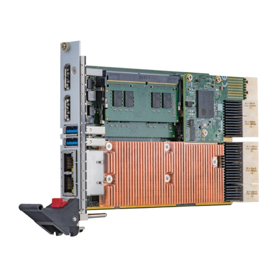
- Page 1 Series ® Performance 3U CompactPCI Serial ® ® ® Gen Intel Core™ / Intel Xeon Processor Blade User’s Manual Manual Rev.: 0.1 preliminary Revision Date: March 24, 2021 Part No: 50M-00008-1000...
- Page 2 Revision History Revision Release Date Description of Change(s) 24/03/2021 Preliminary release Revision History...
-
Page 3: Preface
Preface Copyright © 2021 ADLINK Technology Inc. This document contains proprietary information protected by copy- right. All rights are reserved. No part of this manual may be repro- duced by any mechanical, electronic, or other means in any form without prior written permission of the manufacturer. - Page 4 California Proposition 65 Warning WARNING: This product can expose you to chemicals including acrylamide, arsenic, benzene, cadmium, Tris(1,3-dichloro-2-propyl) phosphate (TDCPP), 1,4-Dioxane, formaldehyde, lead, DEHP, styrene, DINP, BBP, PVC, and vinyl materials, which are known to the State of Califor- nia to cause cancer, and acrylamide, benzene, cadmium, lead, mercury, phthalates, toluene, DEHP, DIDP, DnHP, DBP, BBP, PVC, and vinyl materials, which are known to the State of Califor- nia to cause birth defects or other reproductive harm.
-
Page 5: Table Of Contents
Block Diagrams..............7 I/O Connectivity Table ............8 Power Requirements ............9 3 Board Interfaces ............... 11 cPCI-A3525 Series Board Layout........11 cPCI-A3525 Blade Assembly Layout......... 12 cPCI-A3525 Faceplate............13 Connector Pin Assignments ..........15 Important Safety Instructions ..........21 Getting Service.............. - Page 6 This page intentionally left blank. Table of Contents...
-
Page 7: List Of Figures
List of Figures Figure 2-1: cPCI-A3525 Processor Blade Functional Block Diagram 7 Figure 3-1: cPCI-A3525 Series Board Layout (component side) ..11 Figure 3-2: cPCI-A3525 Blade Assembly Layout......12 Figure 3-3: cPCI-A3525 Faceplate Layout........13 List of Figures... - Page 8 This page intentionally left blank. viii List of Figures...
-
Page 9: List Of Tables
cPCI-A3525 List of Tables Table 2-1: cPCI-A3525 Processor Blade Specifications....5 Table 2-2: cPCI-A3525 I/O Connectivity ........... 8 Table 3-1: cPCI-A3525 Faceplate System LED Descriptions..14 Table 3-2: USB 2.0 Pin Definition ........... 15 Table 3-3: USB 3.0 Pin Definition ........... 15 Table 3-4: DisplayPort Pin Definition .......... - Page 10 This page intentionally left blank. List of Tables...
-
Page 11: Introduction
The ADLINK cPCI-A3525 Series is a 3U CompactPCI Serial com- patible processor blade with SO-DIMM DDR4-2666 ECC memory up to 64GB. The ADLINK cPCI-A3525 features a 8th/9th genera- tion Intel®... -
Page 12: Features
eral slots, and Smart Embedded Management Agent (SEMA) for system health monitoring. In addition, with multiple operating sys- tem and board support package (BSP) support, users can build a reliable and high-performance industrial system with cPCI-A3525 Series. 1.2 Features 3U CompactPCI Serial (PICMG CPCI-S.0) processor blade in 4HP width form factor 9th generation Intel®... -
Page 13: Model Number Decoder
cPCI-A3525 Model Number Decoder c P C I - A 3 5 2 5 /9 8 5 0 H L / M 1 6 ( A ) (B ) ( C ) ( D ) (A) Operating Temperature Code Blank = -20°C to +70°C EX= -40°C to +85°C (for CPUs with TDP below 37W only) (B) Configuration Code Blank = Single slot width, 1x DP, 2x GbE, 2x USB 3.0... -
Page 14: Package Contents
Please obtain authorization before returning any prod- uct to ADLINK. The packing contents of cPCI-A3525 Series non-standard configurations will vary depending on customer requests. -
Page 15: Specifications
cPCI-A3525 Specifications 2.1 cPCI-A3525 Processor Blade Specifications CompactPCI S.0 • PICMG 2.0 CPCI-S.0 CompactPCI® Serial R1.0 Standards Mechanical • Standard 3U CompactPCI • Board size: 100mm x 160mm • Single slot (4HP, 20.32mm) • CompactPCI Serial P1 to P6 connector Processor •... - Page 16 Faceplate I/O • 2x USB 3.0/2.0 ports • 2x 10/100/1000BASE-T Ethernet ports • 2x DisplayPort • Microsoft Windows 10 64-bit Compatibility Environmental • Operating Temperature (with forced air flow) Standard: -20°C to 70°C Extreme temperature: -40°C to +85°C (screened, by Intel cTDP and forced air flow) •...
-
Page 17: Block Diagrams
cPCI-A3525 2.2 Block Diagrams cPCI-A3525 Processor Blade SO-DIMM 1 SO-DIMM 2 Front CH B CH A Panel JTAG DDI 1 (Port B) DP 1 PCIe x8 Gen3 Intel Processor DDI 2 (Port C) DP 2 Coffee Lake-H PCIe x8 Gen3 PCIe x2 Gen2 1x USB 3.0 USB 1... -
Page 18: I/O Connectivity Table
2.3 I/O Connectivity Table cPCI-A3525 (4HP) Function Faceplate Onboard 2 (RJ-45) — 2 (3.0) — Display 2 (DP) — Onboard SSD — Table 2-2: cPCI-A3525 I/O Connectivity Specifications... -
Page 19: Power Requirements
Power Consumption This section provides information on the power consumption of ® cPCI-A3525 Series when using Intel Core™ i7 processors with 16GB DDR4-2666 SO-DIMM memory and 2.5" SATA 256GB SATA SSD. The cPCI-A3525 is powered by +12V only. - Page 20 This page intentionally left blank. Specifications...
-
Page 21: Board Interfaces
P1 to P5 connectors ® CN3201 Storage/Ethernet daughter Intel CM246 Chipset board connector BAT1 CMOS battery DP1/2 DisplayPort connector USB1/2 USB connectors LAN1 Dual Ethernet connectors DIMM1/2 DDR4 SO-DIMM Sockets Figure 3-1: cPCI-A3525 Series Board Layout (component side) Board Interfaces... -
Page 22: Cpci-A3525 Blade Assembly Layout
3.2 cPCI-A3525 Blade Assembly Layout This section describes the final assembly layout of the single slot cPCI-A3525 Blade. DB-P620 Figure 3-2: cPCI-A3525 Blade Assembly Layout DB-P620 Daughter board CompactPCI Serial P6 connector Board Interfaces... -
Page 23: Cpci-A3525 Faceplate
cPCI-A3525 3.3 cPCI-A3525 Faceplate GbE 1/2 USB3.0 Storage Power BIOS Load DisplayPort Thermal Default Button Reset Button Figure 3-3: cPCI-A3525 Faceplate Layout Board Interfaces... -
Page 24: Table 3-1: Cpci-A3525 Faceplate System Led Descriptions
System LEDs Color Condition Indication System is off Power Green/ System POST OK Green Power OK No Watchdog event Amber Blinking Watchdog event alert No SSD/mSATA/SATA drive activity Drive Blue Data read/write in process for SSD/ Blinking mSATA/SATA drive Overheat CPU temperature is under 95ºC Blinking CPU temperature exceeds 95ºC... -
Page 25: Connector Pin Assignments
cPCI-A3525 3.4 Connector Pin Assignments USB 2.0 Connectors Pin # Signal Name UV0- UV0+ Table 3-2: USB 2.0 Pin Definition USB 3.0 Connectors Pin # Signal Name USB3.0_P5VA USB2_CMAN USB2_CMAP USB3A_CMRXN USB3A_CMRXP USB3A_CMTXN USB3A_CMTXP Table 3-3: USB 3.0 Pin Definition Board Interfaces... -
Page 26: Table 3-4: Displayport Pin Definition
DisplayPort Connectors Pin # Signal Pin # Signal CN_DP0_P Ground CN_DP0_N CN_DP1_P Ground CN_DP1_N CN_DP2_P Ground CN_DP2_N CN_DP3_P Ground CN_DP3_N CN_CAD-L CN_CEC CN_AUX_P Ground CN_AUX_N DDP_HPD Ground P3V3 Table 3-4: DisplayPort Pin Definition Board Interfaces... -
Page 27: Table 3-5: Rj-45 Gbe Pin Definitions
cPCI-A3525 RJ-45 Gigabit Ethernet Connectors 10BASE-T/ Pin # 1000BASE-T 100BASE-TX LAN_TX0+ LAN_TX0- LAN_TX1+ — LAN_TX2+ — LAN_TX2- LAN_TX1- — LAN_TX3+ — LAN_TX3- Table 3-5: RJ-45 GbE Pin Definitions Speed Activity Speed LED Activity LED Status (Green/Orange) (Yellow) Network link is not established or system powered off Link 10 Mbps... - Page 28 CompactPCI Serial Connector P1 PEG_ PEG_ PEG_ PEG_ PEG_ PEG_ PEG_ PEG_ RX3_ RX3_ TX3_ TX3_ RX2_ RX2_ TX2_ TX2_ PEG_ PEG_ PEG_ PEG_ PEG_ PEG_ PEG_ PEG_ RX1_ RX1_ TX1_ TX1_ RX0_ RX0_ TX0_ TX0_ USB2 USB2 USB3 USB3 USB3 USB3 _R4N...
- Page 29 cPCI-A3525 CompactPCI Serial Connector P3 SATA SATA_ SATA SATA SATA_ SATA_ SATA SATA _8RN _8TN _8TP _7TN _7TP SATA_ SATA SATA SATA SATA_ SATA SATA SATA _6RP _6TN _6TP _5RP _5TN _5TP SATA SATA_ SATA SATA SATA_ SATA_ SATA SATA _4RN _4TN _4TP...
- Page 30 CompactPCI Serial Connector P5 CLK8_ CLK7_ CLK8_ CLK8_ CLK7_ CLK7_ REQ-L REQ-L CLK3_ CLK3_ CLK3_ CLK2_ CLK2 CLK2 CLK1_ CLK1 CLK1 REQ-L REQ-L REQ-L PCIE_ PCIE_ PCIE_ PCIE_ PCIE_ PCIE_ PCIE_ PCIE_ GN D 8RN3 8RP3 8TN3 8TP3 8RN2 8RP2 8TN2 8TP2 PCIE_...
-
Page 31: Important Safety Instructions
cPCI-A3525 Important Safety Instructions For user safety, please read and follow all instructions, WARNINGS, CAUTIONS, and NOTES marked in this manual and on the associated equipment before handling/operating the equipment. Read these safety instructions carefully. Keep this user’s manual for future reference. Read the specifications section of this manual for detailed information on the operating environment of this equipment. - Page 32 Never attempt to fix the equipment. Equipment should only be serviced by qualified personnel. A Lithium-type battery may be provided for uninterrupted, backup or emergency power. Risk of explosion if battery is replaced with one of an incorrect type. Dispose of used batteries appropriately. WARNING: Equipment must be serviced by authorized technicians when:...
-
Page 33: Getting Service
San Jose, CA 95138, USA Tel: +1-408-360-0200 Toll Free: +1-800-966-5200 (USA only) Fax: +1-408-360-0222 Email: info@adlinktech.com ADLINK Technology (China) Co., Ltd. 300 Fang Chun Rd., Zhangjiang Hi-Tech Park Pudong New Area, Shanghai, 201203 China Tel: +86-21-5132-8988 Fax: +86-21-5132-3588 Email: market@adlinktech.com...
Need help?
Do you have a question about the cPCI-A3525 Series and is the answer not in the manual?
Questions and answers