
Related Manuals for ADLINK Technology cPCI-A3515 Series


Summary of Contents for ADLINK Technology cPCI-A3515 Series
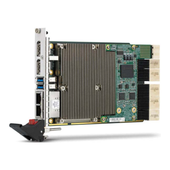
- Page 1 Series ® Performance 3U CompactPCI Serial ® Gen Intel Core™ Processor Blade User’s Manual Manual Rev.: Revision Date: February 27, 2018 Part No: 50-15105-2000 Leading EDGE COMPUTING...
- Page 2 Leading EDGE COMPUTING Revision History Revision Release Date Description of Change(s) 27/02/2018 Initial release Revision History...
-
Page 3: Preface
Preface Copyright 2018 ADLINK Technology Inc. This document contains proprietary information protected by copy- right. All rights are reserved. No part of this manual may be repro- duced by any mechanical, electronic, or other means in any form without prior written permission of the manufacturer. - Page 4 Leading EDGE COMPUTING Trademarks Product names mentioned herein are used for identification pur- poses only and may be trademarks and/or registered trademarks of their respective companies. Conventions Take note of the following conventions used throughout this manual to make sure that users perform certain tasks and instructions properly.
-
Page 5: Table Of Contents
Platform Controller Hub ............. 15 Intel® Turbo Boost Technology ......... 16 Intel® Hyper-Threading Technology........16 Trusted Platform Module ........... 16 Battery ................17 4 Board Interfaces ............... 19 cPCI-A3515 Series Board Layout........19 cPCI-A3515 Blade Assembly Layout......... 21 Table of Contents... - Page 6 Leading EDGE COMPUTING cPCI-A3515B Blade Assembly Layout....... 22 cPCI-A3515D Blade Assembly Layout ......24 cPCI-A3515/B/D Faceplate..........26 Connector Pin Assignments..........28 5 Getting Started ..............39 CPU and Heatsink ............. 39 SATA Drive Installation ............40 Installing an mSATA Drive ..........43 Installing the cPCI-A3515 to the Chassis......
- Page 7 cPCI-A3515 8.3.10Platform Misc Configuration........... 81 8.3.11SATA Configuration ............82 8.3.12Network Stack Configuration ......... 84 8.3.13CSM Configuration ............85 8.3.14USB Configuration ............87 Chipset Setup ..............89 8.4.1 System Agent (SA) Configuration........90 8.4.2 PCH-IO Configuration............ 93 Boot Settings ..............96 Security Setup ..............
- Page 8 Leading EDGE COMPUTING This page intentionally left blank. viii Table of Contents...
-
Page 9: List Of Figures
Figure 2-2: cPCI-A3515B Daughter Board Functional Block Diagram9 Figure 2-3: cPCI-A3515D Daughter Board Functional Block Diagram10 Figure 4-1: cPCI-A3515 Series Board Layout (component side) ..19 Figure 4-2: cPCI-A3515 Series Board Layout (solder side) ..... 20 Figure 4-3: cPCI-A3515 Blade Assembly Layout......21 Figure 4-4: cPCI-A3515B Blade Assembly Layout ...... - Page 10 Leading EDGE COMPUTING This page intentionally left blank. List of Figures...
-
Page 11: List Of Tables
cPCI-A3515 List of Tables Table 2-1: cPCI-A3515 Processor Blade Specifications....5 Table 2-2: cPCI-A3515 I/O Connectivity ......... 11 Table 4-1: cPCI-A3515 Faceplate System LED Descriptions..27 Table 4-2: USB 2.0 Pin Definition ........... 28 Table 4-3: USB 3.0 Pin Definition ........... 28 Table 4-4: VGA Pin Definition ............ - Page 12 Leading EDGE COMPUTING This page intentionally left blank. List of Tables...
-
Page 13: Introduction
The ADLINK cPCI-A3515 Series is a 3U CompactPCI Serial com- patible processor blade with soldered DDR3L-1333/1600 ECC memory up to 16GB. The ADLINK cPCI-A3515 features a 4 ®... -
Page 14: Features
Leading EDGE COMPUTING Serial interfaces on the backplane connectors P1 to P5 include one PCI Express x8, two PCI Express x4, three PCI Express x1, four SATA 6Gb/s, two USB 3.0, and eight USB 2.0 ports. Addition- ally, the P6 connector supports up to eight Gigabit Ethernet inter- faces. -
Page 15: Model Number Decoder
cPCI-A3515 Model Number Decoder cPCI- EX A3515 /5700E /M16 /S32 (A) Operating Temperature Code Blank = -20°C to +70°C EX= -40°C to +85°C (for CPUs with TDP below 37W only) (B) Configuration Code Blank = Single slot width, 2x DP, 2x GbE, 2x USB 3.0 B = Dual slot width, 2x DP, 2x GbE, 2x USB 3.0, COM, 2x USB 2.0, VGA, mSATA socket, SATA connector, Compact- PCI J1 and J2 connectors... -
Page 16: Package Contents
Please obtain authorization before returning any prod- uct to ADLINK. The packing contents of cPCI-A3515 Series non-standard configurations will vary depending on customer requests. -
Page 17: Specifications
cPCI-A3515 Specifications 2.1 cPCI-A3515 Processor Blade Specifications CompactPCI • PICMG 2.0 CPCI-S.0 CompactPCI® Serial R1.0 Standards • PICMG CompactPCI® Rev. 3.0 Mechanical • Standard 3U CompactPCI • Board size: 100mm x 160mm • Single slot (4HP, 20.32mm); dual slot (8HP, 40.64mm) •... - Page 18 Leading EDGE COMPUTING Atmel AT97SC3204 TPM (upon request) supporting: • Over/Under voltage detection • Low/High frequency sensor/filter • Reset filter • Memory encryption/decryption Storage • mSATA socket on daughter board • Optional onboard 32GB SSD on daughter board Interfaces • One SATA 3Gb/s direct connector for 2.5" SATA drive on 8HP versions (cPCI-A3515B/D) Faceplate I/O 4HP (cPCI-A3515)
- Page 19 cPCI-A3515 • CE EN55022 • FCC Class A Table 2-1: cPCI-A3515 Processor Blade Specifications 1. The cPCI-A3515B supporting CompactPCI bus requires a PICMG CPCI-S.0 backplane with system slot on the left and a PICMG 2.0 backplane with system slot on the right. Please contact your ADLINK representative for detailed information on compatible backplanes.
-
Page 20: Block Diagrams
Leading EDGE COMPUTING 2.2 Block Diagrams cPCI-A3515 Processor Blade Faceplate 1x Gen3 PCIe x8 DP 1 2x Gen3 PCIe x4 DP 2 Intel® Core™ 3x Gen2 PCIe x1 USB 1 SMBus 2x USB 3.0 USB 2 2x PCIe x1 2x USB 3.0 + 8x USB 2.0 1x SATA 3Gb/s B2B-1 4x SATA 6Gb/s... - Page 21 cPCI-A3515 cPCI-A3515B Daughter Board PCIe x1 PCI 32-bit, 33/66MHz PCIe-to-PCI J1/2 Bridge Faceplate RS-232/422/485 USB 1 2x USB 2.0 B2B-2 USB 2 SATA 3Gb/s HDD/SSD Figure 2-2: cPCI-A3515B Daughter Board Functional Block Diagram Specifications...
- Page 22 Leading EDGE COMPUTING cPCI-A3515D Daughter Board Faceplate RS-232/422/485 USB 1 2x USB 2.0 B2B-2 USB 2 Line-in, Line-in, Codec Line-out Line-out SATA 3Gb/s HDD/SSD Figure 2-3: cPCI-A3515D Daughter Board Functional Block Diagram Specifications...
-
Page 23: I/O Connectivity Table
cPCI-A3515 2.3 I/O Connectivity Table cPCI-A3515 (4HP) cPCI-A3515B (8HP) cPCI-A3515D (8HP) Function Faceplate Onboard Faceplate Onboard Faceplate Onboard 2 (RJ-45) — 2 (RJ-45) — 2 (RJ-45) — 2 (3.0) 2 (3.0) 2 (3.0) — — — 2 (2.0) 2 (2.0) —... -
Page 24: Power Requirements
Power Consumption This section provides information on the power consumption of ® cPCI-A3515 Series when using Intel Core™ i7 processors with 16GB DDR3L-1333 ECC soldered memory and 2.5” SATA 64GB SATA SSD. The cPCI-A3515 is powered by +12V only. -
Page 25: Functional Description
The processor includes an Integrated Display Engine, Processor Graphics and Integrated Memory Controller. The cPCI-A3515 Series supports Intel® Core™ i7 processors. The table below lists the general specifications and power ratings of the CPUs supported by the cPCI-A3515 Series. - Page 26 Leading EDGE COMPUTING Supported Technologies Features Core™ i7-5700EQ Core™ i7-4700EQ Intel® Virtualization Technology for Directed I/O (Intel® VT-d) Intel® Virtualization Technology (Intel® VT-x) Intel® VT-x with Extended Page Tables (EPT) Intel® Transactional Synchronization Extensions - New Instructions (Intel® TSX-NI) Intel® Hyper-Threading Technology Intel®...
-
Page 27: Platform Controller Hub
cPCI-A3515 assuming dual-channel mode with x8, dual-ranked ECC SDRAM) PCI Express ports are fully-compliant with the PCI Express Base Specification, Revision 2.0. 5 GT/s point-to-point DMI interface to PCH is supported 3.2 Platform Controller Hub The Mobile Intel® QM87 Chipset provides extensive I/O support. Functions and capabilities include: PCI Express Base Specification, Revision 2.0 support for up to eight ports with transfers up to 5 GT/s... -
Page 28: Intel® Turbo Boost Technology
Leading EDGE COMPUTING 3.3 Intel® Turbo Boost Technology Intel® Turbo Boost Technology is a feature that allows the proces- sor to opportunistically and automatically run faster than its rated operating core and/or render clock frequency when there is suffi- cient power headroom, and the product is within specified temper- ature and current limits. -
Page 29: Battery
cPCI-A3515 The key features Trusted Platform Module (TPM) offers are: Fully compliant to the Trusted Computing Group (TCG) Trusted Platform Module (TPM) version 1.2 specification Hardware hash accelerator for SHA-1 algorithm Advanced Crypto Engine (ACE) for asymmetric key opera- tions (up to 2048-bit key length) to make hardware protec- tion. - Page 30 Leading EDGE COMPUTING This page intentionally left blank. Functional Description...
-
Page 31: Board Interfaces
P1-P5 CompactPCI Serial P1 to P5 connectors ® CN3201 Storage/Ethernet daughter Intel QM87 PCH board connector BAT1 CMOS battery DP1/ DisplayPort connector USB1 Dual USB connectors LAN1 Dual Ethernet connectors Figure 4-1: cPCI-A3515 Series Board Layout (component side) Board Interfaces... -
Page 32: Figure 4-2: Cpci-A3515 Series Board Layout (Solder Side)
Leading EDGE COMPUTING CN3202 Reset Button CN3202 Layer-2 daughter board connector Figure 4-2: cPCI-A3515 Series Board Layout (solder side) Board Interfaces... -
Page 33: Cpci-A3515 Blade Assembly Layout
cPCI-A3515 4.2 cPCI-A3515 Blade Assembly Layout This section describes the final assembly layout of the single slot cPCI-A3515 Blade. Heat Sink Figure 4-3: cPCI-A3515 Blade Assembly Layout Onboard SSD CompactPCI Serial P6 connector Board Interfaces... -
Page 34: Cpci-A3515B Blade Assembly Layout
Leading EDGE COMPUTING 4.3 cPCI-A3515B Blade Assembly Layout The dual-slot width cPCI-A3515B Blade is comprised of the cPCI-A3515 single-slot main board and the cPCI-A3515B layer-2 daughter board to expand I/O connectivity with COM, 2x USB 2.0, and VGA. cPCI-A3515 Main Board Layer-2 Daughter Board SATA0 COM1... -
Page 35: Figure 4-5: Cpci-A3515B Daughter Board Solder Side Layout
cPCI-A3515 SW801 SW801 COM1 mode selection switch Figure 4-5: cPCI-A3515B Daughter Board Solder Side Layout Board Interfaces... -
Page 36: Cpci-A3515D Blade Assembly Layout
Leading EDGE COMPUTING 4.4 cPCI-A3515D Blade Assembly Layout The dual-slot width cPCI-A3515D is comprised of the cPCI-A3515 single-slot main board and cPCI-A3515D layer-2 daughter board to expand I/O connectivity with COM, 2x USB 2.0, Line-in and Line-out. cPCI-A3515 Main Board Layer-2 Daughter Board SATA0 COM1... -
Page 37: Figure 4-7: Cpci-A3515D Daughter Board Solder Side Layout
cPCI-A3515 SW801 SW801 COM1 mode selection switch Figure 4-7: cPCI-A3515D Daughter Board Solder Side Layout Board Interfaces... -
Page 38: Cpci-A3515/B/D Faceplate
Leading EDGE COMPUTING 4.5 cPCI-A3515/B/D Faceplate USB 3.0 GbE 1/2 Thermal DisplayPort Storage Power Reset cPCI-A3515 Faceplate Button Reset DisplayPort USB 3.0 Button GbE 1/2 GP LED Thermal Power Storage USB 2.0 cPCI-A3515B Faceplate Reset DisplayPort USB 3.0 Button GbE 1/2 GP LED Thermal Power... -
Page 39: Table 4-1: Cpci-A3515 Faceplate System Led Descriptions
cPCI-A3515 System LEDs Color Condition Indication System is off Power Green/ System Power ready (PWGD) Green Post OK No Watchdog event Orange Blinking Watchdog event alert No SSD/mSATA/SATA drive activity Drive Blue Data read/write in process for SSD/ Blinking mSATA/SATA drive Overheat CPU temperature is under 100ºC CPU temperature exceeds 100ºC... -
Page 40: Connector Pin Assignments
Leading EDGE COMPUTING 4.6 Connector Pin Assignments USB 2.0 Connectors Pin # Signal Name UV0- UV0+ Table 4-2: USB 2.0 Pin Definition USB 3.0 Connectors Pin # Signal Name USB3.0_P5VA USB2_CMAN USB2_CMAP USB3A_CMRXN USB3A_CMRXP USB3A_CMTXN USB3A_CMTXP Table 4-3: USB 3.0 Pin Definition Board Interfaces... -
Page 41: Table 4-4: Vga Pin Definition
cPCI-A3515 DB-15 VGA Connector Signal Name Pin # Pin # Signal Name Green Blue N.C. +5V. N.C. CRTDATA HSYNC VSYNC CRTCLK Table 4-4: VGA Pin Definition DisplayPort Connectors Pin # Signal Pin # Signal CN_DP0_P Ground CN_DP0_N CN_DP1_P Ground CN_DP1_N CN_DP2_P Ground CN_DP2_N... -
Page 42: Table 4-6: Rj-45 Gbe Pin Definitions
Leading EDGE COMPUTING RJ-45 Gigabit Ethernet Connectors 10BASE-T/ Pin # 1000BASE-T 100BASE-TX LAN_TX0+ LAN_TX0- LAN_TX1+ — LAN_TX2+ — LAN_TX2- LAN_TX1- — LAN_TX3+ — LAN_TX3- Table 4-6: RJ-45 GbE Pin Definitions Speed Activity Speed LED Activity LED Status (Green/Orange) (Yellow) Network link is not established or system powered off Link 10 Mbps... -
Page 43: Table 4-8: Cpci-A3515D/P Com1 (Db-9) Pin Definition
cPCI-A3515 cPCI-A3515B/D Serial Port COM1 Connector (DB-9) Pin # RS-232 RS-422 RS-485(+) DCD-L TXD- TXD- TXD+ TXD+ RXD+ — DTR-L RXD- — DSR-L — — RTS-L — — CTS-L — — RI-L — — Table 4-8: cPCI-A3515D/P COM1 (DB-9) Pin Definition COM1 Mode Selection Switch (SW801) This switch sets the cPCI-A3515B/D COM1 port to RS-232 full modem, RS-422, RS-485. -
Page 44: Table 4-10: Sata On Cpci-A3515B/D Daughter Board Pin Def'n
Leading EDGE COMPUTING SATA Conn. on cPCI-A3515B/D Daughter Board Pin # Signal Signal Power P13~P15 Table 4-10: SATA on cPCI-A3515B/D Daughter Board Pin Def’n Board Interfaces... -
Page 45: Table 4-11: Msata Socket Pin Definition
cPCI-A3515 mSATA Socket on Storage/Ethernet Daughter Board Pin # Signal Name Pin # Signal Name +3V3 Reserved SATA_RX0_P +3V3 SATA_RX0_N Reserved SATA_TX0_N SATA_TX0_P +3V3 +3V3 Reserved +3V3 Table 4-11: mSATA Socket Pin Definition Board Interfaces... -
Page 46: Table 4-12: Compactpci J1 Connector Pin Definition
Leading EDGE COMPUTING CompactPCI J1 Connector (cPCI-A3515B only) REQ64# ENUM# CPCI_AD1 CPCI_VIO CPCI_AD0 ACK64# CPCI_AD4 CPCI_AD3 CPCI_AD2 CPCI_AD7 CPCI_AD6 CPCI_AD5 CPCI_AD9 CPCI_AD8 CPCI_M66EN CPCI_CBE-L0 GND CPCI_AD12 CPCI_AD11 CPCI_AD10 CPCI_AD15 CPCI_AD14 CPCI_AD13 GND CPCI_SERR-L CPCI_PAR CPCI_CBE-L1 GND CPCI_PERR-L GND GND CPCI_DEVSEL-L CPCI_STOP-L CPCI_LOCK-L GND CPCI_FRAME-L CPCI_IRDY-L CPCI_BDSEL# CPCI_TRDY-L GND... -
Page 47: Table 4-13: Compactpci J2 Connector Pin Definition
cPCI-A3515 CompactPCI J2 Connector (cPCI-A3515B only) CPCI_CLK6 CPCI_CLK5 J2_RSTJ PCI_REQ6-L PCI_GNT6-L PCI_REQ5-L PCI_GNT5-L CPCI_VIO CPCI_VIO CPCI_VIO CPCI_VIO CPCI_VIO CPCI_VIO CPCI_CLK4 PCI_GNT3-L PCI_REQ4-L PCI_GNT4-L CPCI_SYSEN- CPCI_CLK2 CPCI_CLK3 PCI_GNT2-L JCPCI_REQ3-L GND CPCI_CLK1 PCI_REQ1-L PCI_GNT1-L PCI_REQ2-L Table 4-13: CompactPCI J2 Connector Pin Definition Board Interfaces... - Page 48 Leading EDGE COMPUTING CompactPCI Serial Connector P1 PEG_ PEG_ PEG_ PEG_ PEG_ PEG_ PEG_ PEG_ RXN3 RXP3 TXN3 TXP3 RXN2 RXP2 TXN2 TXP2 PEG_ PEG_ PEG_ PEG_ PEG_ PEG_ PEG_ PEG_ RXN1 RXP1 TXN1 TXP1 RXN0 RXP0 TXN0 TXP0 TP340 TP340 TP340 TP340...
- Page 49 cPCI-A3515 CompactPCI Serial Connector P3 CN_SAT CN_SAT SATA SATA CN_SAT CN_SAT SATA SATA A_PCH_ A_PCH_ _TX- _TX-P A_PCH_ A_PCH_ _TX- _TX- RX-N3 RX-P3 RX-N2 RX-P2 CN_SAT CN_SAT SATA SATA CN_SAT CN_SAT SATA SATA A_PCH_ A_PCH_ _TX- _TX- A_PCH_ A_PCH_ _TX- _TX- RX-N1 RX-P1...
- Page 50 1_ET 1_ET 1_ET 1_ET H_D- H_D+ H_C- H_C+ H_B- H_B+ H_A- H_A+ The signals in red are not supported on cPCI-A3515 Series standard models. Please contact your ADLINK representative if full CompactPCI Serial pinout is required. NOTE: NOTE: Board Interfaces...
-
Page 51: Getting Started
2.5" SATA storage drive mSATA drive Processor blade installation to chassis 5.1 CPU and Heatsink The cPCI-A3515 Series come with CPU and heatsink pre-installed. Removal of heatsink/CPU by users is not recommended. Please contact your ADLINK service representative for assistance. Getting Started... -
Page 52: Sata Drive Installation
Leading EDGE COMPUTING 5.2 SATA Drive Installation The cPCI-A3515B/D 2-slot versions provide space to install a slim type 2.5" Serial-ATA storage drive. SATA Drive Installing a - cPCI-A3515B 1. 1.Remove the 6 screws from the faceplate circled in red. 2. Remove the 5 screws from the solder side of the blade circled in red. - Page 53 cPCI-A3515 3. First, detach the daughter board from the board-to-board connector on the cPCI-A3515 blade (1); then remove daughter board in the direction shown (2). 4. Place the daughter board on a flat surface as shown. 2.5” SATA Drive Location Getting Started...
- Page 54 Leading EDGE COMPUTING 5. Insert the SATA drive into the onboard SATA connector until it is fully seated and attach it with four screws as shown 6. Reinstall the daughter board to faceplate (1) and board-to-board connector (2) on the cPCI-A3515 blade by reversing the steps in Step 3 above.
-
Page 55: Installing An Msata Drive
cPCI-A3515 5.3 Installing an mSATA Drive An mSATA drive can be installed to the underside of the Stor- age/Ethernet daughter board of the cPCI-A3515. 1. Remove the 4 screws securing the Storage/Ethernet daughter board to the cPCI-A3515 processor blade as indicated. - Page 56 Leading EDGE COMPUTING 3. Insert the mSATA drive into the socket at about a 30-degree angle as shown. 4. Secure the mSATA drive with two M2.5 screws. 5. Reinstall the daughter board to the cPCI-A3515 proces- sor blade and secure it with the 4 screws removed in Step 1.
-
Page 57: Installing The Cpci-A3515 To The Chassis
cPCI-A3515 5.4 Installing the cPCI-A3515 to the Chassis The cPCI-A3515 may be installed in a system or peripheral slot of a 3U CompactPCI chassis. These instructions are for reference only. Refer to the user guide that comes with the chassis for more information. - Page 58 Leading EDGE COMPUTING This page intentionally left blank. Getting Started...
-
Page 59: Driver Installation
cPCI-A3515 Driver Installation The cPCI-A3515 drivers are available from the ADLINK website ( http://www.adlinktech.com/PD/web/PD_detail.php? cKind=&pid=1570). ADLINK provides validated drivers for Windows 7 64-bit. We recommend using these drivers to ensure compatibility. The VxWorks BSP can be downloaded from the cPCI-A3515 product page on the ADLINK website 6.1 cPCI-A3515 Drivers The following describes the cPCI-A3515 driver installation proce- dures for Windows 7 64-bit. -
Page 60: Ethernet Controller Driver
Leading EDGE COMPUTING 6.2 Ethernet Controller Driver 1. Extract the contents of …\LAN\Intel® I210 Gigabit Net- work connection_Win7 64bit_12.7.28.0.zip. 2. Open the Device Manager and go to Other Devices. You will see a "question mark" next to Ethernet Controller R-click on Ethernet Controller and choose "Update Driver Software…". - Page 61 cPCI-A3515 3. Click “Browse my computer for driver software”. 4. Navigate to the folder where you extracted the contents of the zip file and click “OK”. Click “Next” to install the driver. Driver Installation...
- Page 62 Leading EDGE COMPUTING This page intentionally left blank. Driver Installation...
-
Page 63: Utilities
Health tab after resuming from S4 7.2 Preboot Execution Environment (PXE) ® The cPCI-A3515 Series supports the Intel Preboot Execution Environment (PXE) that is capable of booting up or executing an OS installation through an Ethernet ports. To use PXE, there must be a DHCP server on the network with one or more servers run- ®... -
Page 64: Watchdog Timer
Leading EDGE COMPUTING 7.3 Watchdog Timer The watchdog timer on the cPCI-A3515 can be implemented in the following ways: Embedded Application Programming Interface (EAPI) library functions SEMA library functions Please refer to the SEMA Software Manual for detailed informa- tion: http://www.adlinktech.com/PD/web/PD_detail.php? cKind=&pid=1274. - Page 65 cPCI-A3515 #include "EApi.h" void main(void) // Initialize the library EApiLibInitialize(); // Delay in milliseconds uint32_tDelay = 100; // Event Timeout in milliseconds uint32_tEventTimeout = 100; // Reset Timeout in milliseconds uint32_tResetTimeout = 100; // Start Watchdog uint32_tstatus = EApiWDogStart( Delay, EventTimeout, ResetTimeout );...
-
Page 66: General Purpose Led Control
Leading EDGE COMPUTING 7.4 General Purpose LED Control The cPCI-A3515 has a General Purpose LED that is user pro- grammable. Make sure you have installed the SEMA driver and the cPCI-A3515 SDK library, downloadable from the cPCI-A3515 product page: http://www.adlinktech.com/PD/web/PD_detail.php ?cKind=&pid=1570. - Page 67 cPCI-A3515 Linux: Turn on LED: # cPCI-A3515 1 Turn off LED: # cPCI-A3515 0 Blink LED: # cPCI-A3515 2 SemaApi_SetLED Command Include the relevant header files #include "sema_api.h" Initialize the API library SemaApi_Init(); Call the LED function SemaApi_SetLED(Mode); The available "Mode" parameters of SemaApi_SetLED are as fol- lows: 0: off 1: on...
- Page 68 Leading EDGE COMPUTING // Blink LED SemaApi_SetLED( LED_BLINKING ); // Release resource SemaApi_Close(); Utilities...
-
Page 69: Bios Setup Utility
cPCI-A3515 BIOS Setup Utility The following chapter describes basic navigation for the AMI EFI BIOS setup utility. 8.1 Starting the BIOS To enter the setup screen, follow these steps: 1. Power on the motherboard 2. Press the < Delete > key on your keyboard when you see the following text prompt: <... - Page 70 Leading EDGE COMPUTING Setup Menu The main BIOS setup menu is the first screen that you can navi- gate. Each main BIOS setup menu option is described in this user’s guide. The Main BIOS setup menu screen has two main frames. The left frame displays all the options that can be configured.
- Page 71 cPCI-A3515 There is a hot key legend located in the right frame on most setup screens. NOTE: NOTE: The < F8 > key on your keyboard is the Fail-Safe key. It is not dis- played on the key legend by default. To set the Fail-Safe settings of the BIOS, press the <...
- Page 72 Leading EDGE COMPUTING The < F2 > key on your keyboard is the previous values key. It is not displayed on the key legend by default. To set the previous values settings of the BIOS, press the < F2 > key on your keyboard.
- Page 73 cPCI-A3515 The < F4 > key allows you to save any changes you have made and exit Setup. Press the < F10 > key to save your changes. The following screen will appear: Press the < Enter > key to save the configuration and exit. You can also use the <...
-
Page 74: Main Setup
Leading EDGE COMPUTING 8.2 Main Setup When you first enter the Setup Utility, you will enter the Main setup screen. You can always return to the Main setup screen by select- ing the Main tab. There are two Main Setup options. They are described in this section. - Page 75 cPCI-A3515 System Management BIOS Setup Utility...
- Page 76 Leading EDGE COMPUTING Board Information Displays information from SEMA via the SMBus: SEMA Firm- ware, SEMA Bootloader, Build Date, Hardware Version, Serial Number, Manufacturing Date, Last Repair Date, MAC ID. BIOS Setup Utility...
- Page 77 cPCI-A3515 Temperatures and Fan Speed Power Consumption BIOS Setup Utility...
- Page 78 Leading EDGE COMPUTING Runtime Statistics Flags BIOS Setup Utility...
- Page 79 cPCI-A3515 Power Up Power-Up Watchdog Enable/Disable the Power-Up Watchdog. Pressing F12 during startup disables the Power Up Watchdog. System Time/System Date Use this option to change the system time and date. Highlight Sys- tem Time or System Date using the < Arrow > keys. Enter new val- ues using the keyboard.
-
Page 80: Advanced Bios Setup
Leading EDGE COMPUTING 8.3 Advanced BIOS Setup Select the Advanced tab from the setup screen to enter the Advanced BIOS Setup screen. You can select any of the items in the left frame of the screen, such as SuperIO Configuration, to go to the sub menu for that item. -
Page 81: Cpu Configuration
cPCI-A3515 8.3.1 CPU Configuration You can use this screen to select options for the CPU Configura- tion Settings. Use the up and down < Arrow > keys to select an item. Use the < + > and < - > keys to change the value of the selected option. - Page 82 Leading EDGE COMPUTING Intel Virtualization Technology When enabled, a VMM can utilize the additional hardware capabil- ities provided by Vanderpool Technology. EIST It will allow the user to set the EIST. Turbo Mode It will allow the user to set the Turbo Mode. Configurable TDP Allow reconfiguration of TDP levels base on current power and thermal delivery capabilities of the system..
-
Page 83: Trusted Computing
cPCI-A3515 8.3.2 Trusted Computing Trusted Computing is an industry standard to make personal com- puters more secure through a dedicated hardware chip, called a Trusted Platform Module (TPM). This option allows you to enable or disable the TPM support. TPM Support OS will not show TPM. -
Page 84: Acpi Settings
Leading EDGE COMPUTING 8.3.3 ACPI Settings You can use this screen to select options for the ACPI Advanced Configuration Settings. Use the up and down < Arrow > keys to select an item. Use the < + > and < - > keys to change the value of the selected option. -
Page 85: Pch-Fw Configuration
cPCI-A3515 8.3.4 PCH-FW Configuration You can use this screen to view ME related information. For exam- ple, ME FW Version, ME Firmware Mode, ME Firmware Type, ME Firmware SKU..etc. An example of the ME screen is shown below. BIOS Setup Utility... -
Page 86: Intel ® Anti-Theft Technology Configuration
Leading EDGE COMPUTING 8.3.5 Intel ® Anti-Theft Technology Configuration You can use this screen to select options for the Intel AT Configu- ration Settings. An example of the Intel AT Configuration screen is shown below. Intel® Anti-Theft Support Set this value is Enable/Disable. BIOS Setup Utility... -
Page 87: Amt Configuration
cPCI-A3515 8.3.6 AMT Configuration You can use this screen to select options for the AMT settings. Use the up and down < Arrow > keys to select an item. Use the < + > and < - > keys to change the value of the selected option. Intel AMT Intel AMT feature. -
Page 88: Nct5104D Super Io Configuration
Leading EDGE COMPUTING 8.3.7 NCT5104D Super IO Configuration You can use this screen to select options for the Super IO Config- uration settings. BIOS Setup Utility... - Page 89 cPCI-A3515 Serial Port 1 Configuration Set Parameters of Serial Port 1 (COM 1). Serial Port Enable/Disable serial port 1 (COM1). Set this value to Enable or Disable. Change Settings Set the IO/IRQ of serial port 1 (COM1). BIOS Setup Utility...
-
Page 90: Console Redirection
Leading EDGE COMPUTING 8.3.8 Console Redirection You can use this screen to select options for the serial port con- sole redirection settings. An example of the Serial Port Console Redirection screen is shown below. Console Redirection Set this value to Enabled/Disabled. Console Redirection Settings The settings specify how the host computer and the remote com- puter will exchange data. - Page 91 cPCI-A3515 Terminal Type VT100+ is the preferred terminal type for out-of-band manage- ment. Configuration options: VT100, VT100+, VT-UTF8, ANSI. Bits per second Select the bits per second you want the serial port to use for console redirection. The options are 115200, 57600, 38400, 19200, 9600.
- Page 92 Leading EDGE COMPUTING Stop Bits Stop bits indicate the end of a serial data packet. (A start bit indicates the beginning). The standard setting is 1 stop bit. Communication with slow devices may require more than 1 stop bit. Set this value to 1 and 2. Flow Control Set this option to select Flow Control for console redirection.
-
Page 93: Intel Txt Information
cPCI-A3515 8.3.9 Intel TXT Information 8.3.10 Platform Misc Configuration You can use this screen to enable/disable Intel RMT Support BIOS Setup Utility... -
Page 94: 11Sata Configuration
Leading EDGE COMPUTING 8.3.11 SATA Configuration You can use this screen to select options for the SATA Configura- tion Settings. An example of the SATA Configuration screen is shown below. SATA Controller(s) Enable or disable SATA device. SATA Mode Selection The SATA can be configured as a legacy IDE, RAID and AHCI mode. - Page 95 cPCI-A3515 Hot Plug Appears when SATA mode is AHCI. SATA port Hot Plug support. Set this value to Enabled/Disabled. Software Feature Mask Configuration Use this screen to to enable or disable storage features. BIOS Setup Utility...
-
Page 96: 12Network Stack Configuration
Leading EDGE COMPUTING 8.3.12 Network Stack Configuration Network Stack Enable/Disable the UEFI network stack. IPv4 PXE Support Enable/Disable IPv4 PXE Boot Support. IPv6 PXE Support Enable/Disable IPv6 PXE Boot Support. PXE boot wait time Wait time to press ESC key to abort the PXE boot. Media detect count Wait time in sec to detect media. -
Page 97: 13Csm Configuration
cPCI-A3515 8.3.13 CSM Configuration CSM Support Enable/Disable CSM Support GateA20 Active Upon Request: GA20 can be disabled using BIOS services. Always: do not allow disabling GA20; this option is useful when any RT code is executed above 1MB. Option ROM Messages Set display mode for option ROM. - Page 98 Leading EDGE COMPUTING Storage Controls the execution of UEFI and Legacy Storage OpROM. Video Controls the execution of UEFI and Legacy Video OpROM. Other PCI Devices Determines OpROM execution policy for devices other than Net- work, Storage, or Video BIOS Setup Utility...
-
Page 99: 14Usb Configuration
cPCI-A3515 8.3.14 USB Configuration You can use this screen to select options for the USB Configura- tion. Use the up and down < Arrow > keys to select an item. The screen is shown below. Legacy USB Support Enables legacy USB support. Auto option disables legacy support if no USB devices are connected. - Page 100 Leading EDGE COMPUTING EHCI2 Enable/Disable EHCI 2(USB2.0) controller. USB Mass Storage Driver Support Enable/Disable USB Mass Storage Driver Support. BIOS Setup Utility...
-
Page 101: Chipset Setup
cPCI-A3515 8.4 Chipset Setup Select the Chipset tab from the setup screen to enter the Chipset BIOS Setup screen. You can select any of Chipset BIOS Setup options by highlighting it using the < Arrow > keys. The Chipset BIOS Setup screen is shown below. BIOS Setup Utility... -
Page 102: System Agent (Sa) Configuration
Leading EDGE COMPUTING 8.4.1 System Agent (SA) Configuration VT-d The Intel Virtualization Technology for Directed I/O. Set this value to Enabled/Disabled. BIOS Setup Utility... - Page 103 cPCI-A3515 Graphics Configuration Primary Display Select which graphics device should be the primary display. Set this value to Auto, IGFX, PCI. Internal Graphics Keep IGD enabled based on the setup options. Set this value to Auto, Enabled, Disabled. PEG Port Configuration PEG0 - Gen X Configure PEG0 B0:D1:F0 Gen1-Gen3 PEG1 - Gen X...
- Page 104 Leading EDGE COMPUTING Memory Configuration BIOS Setup Utility...
-
Page 105: Pch-Io Configuration
cPCI-A3515 8.4.2 PCH-IO Configuration PCH LAN Controller Enable or disable on-chip NIC. Wake on LAN (For LAN2 I218 WOL) Enable or Disable integrated LAN to wake the system. (The Wake On LAN cannot be disabled if ME is on at Sx state.) PCIE Wake From DeepSx Wake from DeepSx by the assertion of PCIE. - Page 106 Leading EDGE COMPUTING PCI Express Configuration PCI Express Root Port 1~7 Control the PCI Express Root Ports 1~7 BIOS Setup Utility...
- Page 107 cPCI-A3515 PCH Azalia Configuration Azalia Enable or disable Azalia Driver support. Set this value to Enable/Disable. Azalia Docking Support Enable or disable Azalia Docking Support of the Audio Control- ler. Azalia PME Enable or disable Power Management capability of the Audio Controller.
-
Page 108: Boot Settings
Leading EDGE COMPUTING 8.5 Boot Settings Select the Boot tab from the setup screen to enter the Boot BIOS Setup screen. You can select any of the items in the left frame of the screen, such as Boot Device Priority, to go to the sub menu for that item. - Page 109 cPCI-A3515 Quiet Boot Disabled - Set this value to allow the computer system to display the POST messages. Enabled - Set this value to allow the computer system to display the OEM logo. Fast Boot Enables or disables boot with initialization of a minimal set of devices required to launch active boot option.
-
Page 110: Security Setup
Leading EDGE COMPUTING 8.6 Security Setup Administrator, User Password If only the administrator's password is set, then this only limits access to setup and is only asked for when entering setup. If only the user's password is set, then this is a power on password and must be entered to boot or enter setup. -
Page 111: Save & Exit Menu
cPCI-A3515 8.7 Save & Exit Menu Select the Save & Exit tab from the setup screen to enter the Save & Exit BIOS Setup screen. You can display an Exit BIOS Setup option by highlighting it using the < Arrow > keys. The Save & Exit BIOS Setup screen is shown below. - Page 112 Leading EDGE COMPUTING Discard Changes and Reset Reset system setup without saving any changes. Save Changes Save changes done so far to any of the setup options. Discard Changes Discard changes done so far to any of the setup options. Restore Changes Restore/Load Defaults values for all the setup options.
- Page 113 cPCI-A3515 Save as User Defaults Save the changes done so far as user defaults.. Restore User Defaults Save changes done so far to any of the setup options. BIOS Setup Utility...
- Page 114 Leading EDGE COMPUTING This page intentionally left blank. BIOS Setup Utility...
-
Page 115: Important Safety Instructions
cPCI-A3515 Important Safety Instructions For user safety, please read and follow all instructions, WARNINGS, CAUTIONS, and NOTES marked in this manual and on the associated equipment before handling/operating the equipment. Read these safety instructions carefully. Keep this user’s manual for future reference. Read the specifications section of this manual for detailed information on the operating environment of this equipment. - Page 116 Leading EDGE COMPUTING Never attempt to fix the equipment. Equipment should only be serviced by qualified personnel. A Lithium-type battery may be provided for uninterrupted, backup or emergency power. Risk of explosion if battery is replaced with one of an incorrect type.
-
Page 117: Getting Service
San Jose, CA 95138, USA Tel: +1-408-360-0200 Toll Free: +1-800-966-5200 (USA only) Fax: +1-408-360-0222 Email: info@adlinktech.com ADLINK Technology (China) Co., Ltd. 300 Fang Chun Rd., Zhangjiang Hi-Tech Park Pudong New Area, Shanghai, 201203 China Tel: +86-21-5132-8988 Fax: +86-21-5132-3588 Email: market@adlinktech.com...
Need help?
Do you have a question about the cPCI-A3515 Series and is the answer not in the manual?
Questions and answers