
Related Manuals for ADLINK Technology cPCI-3630 Series


Summary of Contents for ADLINK Technology cPCI-3630 Series
- Page 1 Series ® Low-Power 3U CompactPCI ® Quad-Core Intel Atom Processor Blade User’s Manual Manual Rev.: Revision Date: June 16, 2020 Part No.: 50-15112-2000 Leading EDGE COMPUTING...
- Page 2 Leading EDGE COMPUTING Revision History Revision Release Date Description of Change(s) 16-06-2020 Initial release Revision History...
-
Page 3: Preface
Preface Copyright © 2020 ADLINK Technology Inc. This document contains proprietary information protected by copy- right. All rights are reserved. No part of this manual may be repro- duced by any mechanical, electronic, or other means in any form without prior written permission of the manufacturer. - Page 4 Leading EDGE COMPUTING California Proposition 65 Warning WARNING: This product can expose you to chemicals including acrylamide, arsenic, benzene, cadmium, Tris(1,3-dichloro-2-propyl)phosphate (TDCPP), 1,4-Diox- ane, formaldehyde, lead, DEHP, styrene, DINP, BBP, PVC, and vinyl materials, which are known to the State of California to cause cancer, and acrylamide, benzene, cadmium, lead, mercury, phthalates, toluene, DEHP, DIDP, DnHP, DBP, BBP, PVC, and vinyl materials, which are known to the State of California to cause...
-
Page 5: Table Of Contents
3 Functional Description ............ 17 Processors................. 17 XMC................... 20 Intel® Virtualization Technology ........20 Intel® AES New Instructions..........20 Battery ................20 4 Board Interfaces ............... 21 cPCI-3630 Series Board Layout ........21 cPCI-3630 Blade Assembly Layout ........22 Table of Contents... - Page 6 Blade Assembly Layout ......... 26 cPCI-3630T Blade Assembly Layout ......... 27 cPCI-3630TR Blade Assembly Layout....... 28 4.10 cPCI-3630 Series Faceplate ..........29 4.11 cPCI-R3610(T) RTM Board Layout........33 4.12 cPCI-R3610(T) RTM Faceplate ......... 34 4.13 cPCI-3630 Blade Connector Pin Assignments ....35 4.14 cPCI-R3610(T) RTM Connector Pin Assignments.....
- Page 7 cPCI-3630 8.2.3 Board Information ............66 8.2.4 System Date and Time ..........67 Advanced................68 8.3.1 CPU Configuration............68 8.3.2 Power Management ............71 8.3.3 System Management............. 71 8.3.4 Thermal Management............ 73 8.3.5 Watchdog Timer ............73 8.3.6 CSM Configuration ............74 8.3.7 Serial Console Redirection ..........
- Page 8 Leading EDGE COMPUTING This page intentionally left blank. viii Table of Contents...
-
Page 9: List Of Figures
Figure 2-3: cPCI-3630T Daughter Board Functional Block Diagram12 Figure 2-4: cPCI-R3610 RTM Functional Block Diagram ....13 Figure 4-1: cPCI-3630 Series Board Layout ........21 Figure 4-2: cPCI-3630 Blade Assembly Layout ....... 22 Figure 4-3: cPCI-3630D Blade Assembly Layout......23 Figure 4-4: cPCI-3630G Blade Assembly Layout ...... - Page 10 Leading EDGE COMPUTING This page intentionally left blank. List of Figures...
-
Page 11: List Of Tables
cPCI-3630 List of Tables Table 2-1: cPCI-3630 Processor Blade Specifications ..... 7 Table 2-2: cPCI-R3610(T) RTM Specifications....... 10 Table 2-3: cPCI-3630 I/O Connectivity ........... 14 Table 4-1: cPCI-3630 Faceplate System LED Descriptions ... 32 Table 4-2: USB 2.0 Pin Definition ........... 35 Table 4-3: VGA Pin Definition ............ - Page 12 Leading EDGE COMPUTING This page intentionally left blank. List of Tables...
-
Page 13: Introduction
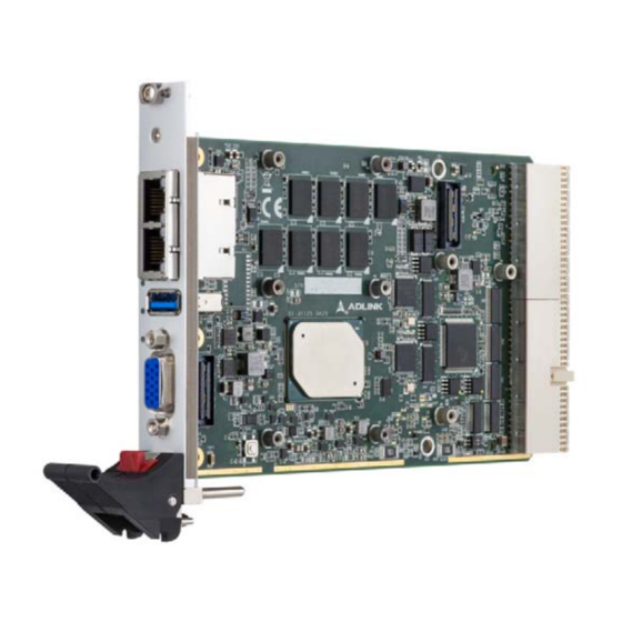
Introduction 1.1 Overview The ADLINK cPCI-3630 Series is a 3U CompactPCI® 2.0 proces- sor blade featuring the 64-bit Intel Atom® Processor X Series SoC (formerly Apollo Lake) and soldered DDR3L-1600 MHz ECC memory up to 8GB. Available in single-slot (4HP) or dual-slot (8HP) width form factors, the cPCI-3630 Series utilizes various daughter boards to provide a broad range of I/O functionality. -
Page 14: Features
Leading EDGE COMPUTING 1.2 Features 3U CompactPCI blade in 4HP or 8HP width form factor 64-bit quad-core Intel Atom® x7-E3950 Processor SoC (1.6GHz, TDP 12W) or dual-core Intel Atom® x5-E3930 Pro- cessor SoC (1.3GHz, TDP 6.5W) Graphics and memory controllers integrated in SoC Compatible with PICMG 2.0 CompactPCI R3.0 and PICMG 2.1 Hot Swap R2.0 Dual channel DDR3L-1600 soldered SDRAM with ECC up to... -
Page 15: Model Number Decoder
cPCI-3630 Model Number Decoder Blades cPCI-3630XX E3950 (A) Configuration Code Blank = Single-slot width, 1x VGA, 1x USB 3.0, 2x GbE D = Dual-slot width, 1x VGA, 1x USB 3.0, 2x GbE on layer 1; 2x USB 2.0, 1x COM (RS-232/422/485), 1x PS/2 KB/MS, Line-in, Line-out and 2.5”... - Page 16 Leading EDGE COMPUTING (B) CPU Code E3950 = Quad-core Intel Atom® x7-E3950 Processor E3930 = Dual-core Intel Atom® x7-E3930 Processor (C) Memory Size Code M4 = 1x 4GB DDR3L-1600 soldered ECC SDRAM M8 = 1x 8GB DDR3L-1600 soldered ECC SDRAM (D) Daughter Board Storage Device Code* Blank = default with no onboard storage S32 = soldered onboard 32GB SSD...
-
Page 17: Package Contents
Please obtain authorization before returning any product to ADLINK. The packing contents of cPCI-3630 Series non-standard configurations will vary depending on customer requests. Processor Blade... - Page 18 Leading EDGE COMPUTING This page intentionally left blank.
-
Page 19: Specifications
cPCI-3630 Specifications 2.1 cPCI-3630 Processor Blade Specifications ® ® • PICMG 2.0 CompactPCI Rev. 3.0 ® CompactPCI ® • PICMG 2.1 Hot Swap Specification Rev. 2.0 Standards ® • Standard 3U CompactPCI Mechanical • Board size: 100mm x 160mm • Single slot (4HP, 20.32mm); Dual slot (8HP, 40.64mm) •... - Page 20 Leading EDGE COMPUTING 4HP (cPCI-3630) • 1x USB 3.0 port • 2x 10/100/1000BASE-T Ethernet ports • 1x VGA port 4HP (cPCI-3630N) • LEDs only (Power, HDD, WDT, GP, GbE), no I/O 8HP (cPCI-3630D) • 1x USB 3.0 ports • 2x 10/100/1000BASE-T Ethernet ports •...
- Page 21 cPCI-3630 • Optional onboard 32GB SSD or mSATA socket on daughter Storage board (mSATA by request) Interfaces • One SATA 3Gb/s direct connector for 2.5" drive (8HP version) • AMI EFI BIOS, dual 16Mbit SPI flash memory BIOS • Microsoft Windows 10 64-bit •...
-
Page 22: Cpci-R3610(T) Rtm Specifications
Leading EDGE COMPUTING 2.2 cPCI-R3610(T) RTM Specifications Board Size • cPCI-R3610: 100mm x 50mm Mechanical • cPCI-R3610T: 100mm x 80mm Dual-slot (8HP, 40.64mm) (optional single slot upon request ) • Two GbE ports switched from cPCI-3630 Gigabit Ethernet • VGA switched from cPCI-3630 Graphics •... -
Page 23: Block Diagrams
cPCI-3630 2.3 Block Diagrams cPCI-3630 Blade Faceplate I/O GbE 2 GbE 1 Intel Intel I210 I210 B2B #3 Buzzer PCIe x1 PCIe x1 SATA 0 DDI 2 DDI 1 4GB DDR3L ECC Soldered 4GB DDR3L ECC Soldered Intel Atom® Processor X Series USB 2.0 PCIe-to-PCI PCIe x1... - Page 24 Leading EDGE COMPUTING cPCI-3630D Daughter Board (DB-3610L2) USB x2 Line-in, Line-out Codec SATA1 Conn. 2.5” Drive PS/2 KB/MS Figure 2-2: cPCI-3630D Daughter Board Functional Block Diagram cPCI-3630T Daughter Board (DB-3620L2) GbE x2 via M12 PCIe x1 82574 x2 PCIe SW SATA0 2.5”...
-
Page 25: Figure 2-4: Cpci-R3610 Rtm Functional Block Diagram
cPCI-3630 cPCI-R3610(T) RTM COM Header x2 GbE x2 USB 2.0 x2 2.5” SSD/HDD Figure 2-4: cPCI-R3610 RTM Functional Block Diagram... -
Page 26: I/O Connectivity Table
Leading EDGE COMPUTING 2.4 I/O Connectivity Table cPCI-3630 (4HP) cPCI-3630D (8HP) cPCI-3630G (8HP) cPCI-3630S (8HP) Function Faceplate Onboard Faceplate Onboard Faceplate Onboard Faceplate Onboard Y x2 Y x2 Y x2 Y x2 — — — — Y (DB-9) Y (RJ-45) —... -
Page 27: Power Requirements
cPCI-3630 Notes for cPCI-3630 Connectivity Table. 1. Switched from faceplate by BIOS setting. 2. VGA switched from faceplate by BIOS setting. 3. SATA1 signal switched from cPCI-3630 by BIOS; SATA2 not connected. 2.5 Power Requirements In order to guarantee a stable functionality of the system, it is rec- ommended to provide more power than the system requires. - Page 28 Power Consumption This section provides information on the power consumption of the cPCI-3630 Series when using Intel Atom® X Series processors with 8GB DDR3L-1600 ECC soldered memory and 2.5" SSD. The cPCI-3630 is powered by 5V. Power consumption in Max mode was measured by running Intel Thermal Analysis Tool (TAT).
-
Page 29: Functional Description
Functional Description The following sections describe the cPCI-3630 Series features and functions. 3.1 Processors ® The cPCI-3630 Series supports the Intel Atom X Series proces- sor which utilizes 22nm process technology with 3-D Tri-Gate tran- sistor to deliver significant improvement in computational performance and energy-efficiency in intelligent systems. - Page 30 Leading EDGE COMPUTING Supported Technologies Technology x7-E3950 x5-E3930 Intel® Turbo Boost Technology Intel® vPro Technology Eligibility Secure Boot Intel® Hyper-Threading Technology Intel® Virtualization Technology Intel® Virtualization Technology for Directed I/O (VT-d) Intel® VT-x with Extended Page Tables (EPT) Intel® 64 Architecture Instruction Set 64-bit 64-bit...
- Page 31 cPCI-3630 Interfaces Dual channel of DDR3L-1600 memory Memory DDR3L data transfer rates of 1600 MT/s ECC soldered memory Maximum 8GB memory capacity supported 64-bit wide channels DDR3L I/O Voltage of 1.35V PCI Express port(s) are fully-compliant with the PCI Express Base Specification, Revision 2.0 Graphics ®...
-
Page 32: Xmc
Leading EDGE COMPUTING 3.2 XMC The cPCI-3630S model supports one XMC site for front panel I/O expansion. The XMC site provides a PCI-Express x1 lane. ® 3.3 Intel Virtualization Technology ® Intel Virtualization Technology (VT-x) allows one hardware plat- form to function as multiple “virtual” platforms. It offers improved manageability by limiting downtime and maintaining productivity by isolating computing activities into separate partitions. -
Page 33: Board Interfaces
4.1 cPCI-3630 Series Board Layout USB 3.0 Board-to-Board ® Intel Atom™ Processor LAN1 Ethernet RJ-45 connector To DB-3610L2 connector LAN2 Ethernet RJ-45 connector To DB-3SSD USB 3.0 port CompactPCI connector J1 DB-15 female VGA connector CompactPCI connector J2 Figure 4-1: cPCI-3630 Series Board Layout... -
Page 34: Cpci-3630 Blade Assembly Layout
Leading EDGE COMPUTING 4.2 cPCI-3630 Blade Assembly Layout This section describes the final assembly layout of the single slot cPCI-3630 blade with the storage daughter board. Heat Sink Battery BSW1 Figure 4-2: cPCI-3630 Blade Assembly Layout BSW1 BIOS setting switch The onboard SSD on the storage daughter board is optional. -
Page 35: Cpci-3630D Blade Assembly Layout
cPCI-3630 4.3 cPCI-3630D Blade Assembly Layout The dual-slot width cPCI-3630D is comprised of the cPCI-3630 single-slot main board and the DB-3610L2 riser card to expand I/O connectivity with PS/2, COM, 2x USB, Line-in, and Line-out ports, and provide mounting space for a 2.5” SATA drive. SATA0 SATA0 22-pin SATA connector Board-to-board connector... -
Page 36: Cpci-3630G Blade Assembly Layout
Leading EDGE COMPUTING 4.4 cPCI-3630G Blade Assembly Layout The dual-slot width cPCI-3630G is comprised of the cPCI-3630 single-slot main board and the DB-3970L2 riser card to expand I/O connectivity with two DisplayPorts, COM, PS/2 KB/MS, USB 2.0 ports, and provide mounting space for a 2.5” SATA drive. An onboard header is provided for COM port expansion. -
Page 37: Cpci-3630M Blade Assembly Layout
cPCI-3630 4.5 cPCI-3630M Blade Assembly Layout The dual-slot width cPCI-3630M is comprised of the cPCI-3630 single-slot main board and the DB-MAX riser card to expand I/O connectivity with one 100-pin connector and provide mounting space for a 2.5” SATA drive. SATA0 SATA0 22-pin SATA connector Board-to-board connector... -
Page 38: Cpci-3630N Blade Assembly Layout
Leading EDGE COMPUTING 4.6 cPCI-3630N Blade Assembly Layout The single-slot width cPCI-3630N is comprised of the cPCI-3630 single-slot main board but with faceplate I/O replaced by LAN sta- tus LEDs for rear I/O. 4.7 cPCI-3630S Blade Assembly Layout The dual-slot width cPCI-3630S is comprised of the cPCI-3630 single-slot main board and the DB-3UMC riser card to expand I/O connectivity with an XMC connector. -
Page 39: Cpci-3630T Blade Assembly Layout
cPCI-3630 4.8 cPCI-3630T Blade Assembly Layout The dual-slot width cPCI-3630T is comprised of the cPCI-3630 single-slot main board and the DB-3620L2 riser card to expand I/O connectivity with COM, 2x GbE with M12 MIL-STD connectors, and provide mounting space for a 2.5" SATA drive. 22-pin SATA connector Figure 4-7: cPCI-3630T Blade Assembly Layout... -
Page 40: Cpci-3630Tr Blade Assembly Layout
Leading EDGE COMPUTING 4.9 cPCI-3630TR Blade Assembly Layout The dual-slot width cPCI-3630TR is comprised of the cPCI-3630 single-slot main board and the DB-3620TRL2 riser card to expand I/O connectivity with COM, 2x GbE connectors, and provide mounting space for a 2.5" SATA drive. 22-pin SATA connector Figure 4-8: cPCI-3630TR Blade Assembly Layout... -
Page 41: Cpci-3630 Series Faceplate
4.10 cPCI-3630 Series Faceplate cPCI-3630 LAN x2 USB 3.0 cPCI-3630D PS/2 USB 2.0 KBMS Audio LAN x2 USB 3.0 cPCI-3630G USB 2.0 DisplayPorts LAN x2 USB 3.0 Figure 4-9: cPCI-3630, cPCI-3630D/G Faceplate Layout... -
Page 42: Figure 4-10: Cpci-3630M/N/S Faceplate Layout
Leading EDGE COMPUTING cPCI-3630M 100-pin connector LAN x2 USB 3.0 cPCI-3630N No I/O, only LAN status LEDs cPCI-3630S LAN x2 USB 3.0 Figure 4-10: cPCI-3630M/N/S Faceplate Layout... -
Page 43: Figure 4-11: Cpci-3630T(R) Faceplate Layout
cPCI-3630 cPCI-3630T M12 LAN LAN x2 USB 3.0 VGA cPCI-3630TR RJ-45 LAN LAN x2 USB 3.0 VGA Figure 4-11: cPCI-3630T(R) Faceplate Layout... -
Page 44: Table 4-1: Cpci-3630 Faceplate System Led Descriptions
Leading EDGE COMPUTING System LEDs Color Condition Indication Defined by user GPIO Yellow ON/Blinking Defined by user Board temperature is below 85°C Thermal Board temperature equals or exceeds 85°C System is off Power Green/ Green Post OK No SATA drive activity Blue Data read/write in process for CF/CFast/ Blinking... -
Page 45: Cpci-R3610(T) Rtm Board Layout
cPCI-3630 4.11 cPCI-R3610(T) RTM Board Layout SATA1 SATA2 COM2 USB 5 SW1-4 COM3 VGA1 SW5-8 COM2 RS-232/422/485 port LAN1/2 Dual Ethernet ports COM3 RS-232/422/485 port VGA1 VGA port SATA1 SATA port switched from USB 2.0 port front by BIOS (SATA2 not connected) CompactPCI connector SW1-8 Switches... -
Page 46: Cpci-R3610(T) Rtm Faceplate
Leading EDGE COMPUTING 4.12 cPCI-R3610(T) RTM Faceplate COM3 COM2 GbE x2 Figure 4-13: cPCI-R3610(T) RTM Faceplate... -
Page 47: Cpci-3630 Blade Connector Pin Assignments
cPCI-3630 4.13 cPCI-3630 Blade Connector Pin Assignments USB 2.0 Connectors Pin # Signal Name UV0- UV0+ Table 4-2: USB 2.0 Pin Definition USB 3.0 Connectors Pin # Signal Name USB3.0_P5VA USB2_CMAN USB2_CMAP USB3A_CMRXN USB3A_CMRXP USB3A_CMTXN USB3A_CMTXP... -
Page 48: Table 4-3: Vga Pin Definition
Leading EDGE COMPUTING DB-15 VGA Connector Signal Name Pin # Pin # Signal Name Green Blue N.C. +5V. N.C. CRTDATA HSYNC VSYNC CRTCLK Table 4-3: VGA Pin Definition PS/2 Keyboard/Mouse Connector Pin # Signal Function KBDATA Keyboard Data MSDATA Mouse Data Ground Power KBCLK... -
Page 49: Table 4-5: Rj-45 Gbe Pin Definitions
cPCI-3630 RJ-45 Gigabit Ethernet Connectors 10BASE-T/ Pin # 1000BASE-T 100BASE-TX LAN_TX0+ LAN_TX0- LAN_TX1+ — LAN_TX2+ — LAN_TX2- LAN_TX1- — LAN_TX3+ — LAN_TX3- Table 4-5: RJ-45 GbE Pin Definitions Speed Activity Speed LED Activity LED Status (Green/Amber) (Yellow) Network link is not established or system powered off Link 10 Mbps... -
Page 50: Table 4-7: Rj-45 Gbe Pin Definitions
Leading EDGE COMPUTING M12 Gigabit Ethernet Connectors Pin # Signal Table 4-7: RJ-45 GbE Pin Definitions cPCI-3630D/T(R) Serial Ports COM1 Connector (DB-9) Pin # RS-232 RS-422 RS-485(+) DCD-L TXD- TXD- TXD+ TXD+ RXD+ — DTR-L RXD- — DSR-L — — RTS-L —... -
Page 51: Table 4-9: Cpci-3630M 100-Pin I/O Connector Pin Definition
cPCI-3630 cPCI-3630M 100-pin I/O Connector Pin # Signal Pin # Signal USB9_CN-N USB9_CN-P USB1_CN-N USB1_CN-P TMDS_I2C_DATA TMDS_I2C_CLK TMDSB_DATA2B TMDSB_DATA2 TMDSB_DATA1B TMDSB_DATA1 TMDSB_DATA0B TMDSB_DATA0 TMDSB_CLKB TMDSB_CLK P5V_DVI1 TMDSB_HPD NC TMDS_I2C_DATA TMDS_I2C_CLK TMDSB_DATA2B TMDSB_DATA2 TMDSB_DATA1B TMDSB_DATA1 TMDSB_DATA0B TMDSB_DATA0 TMDSB_CLKB TMDSB_CLK P5V_DVI2 TMDSB_HPD P5V_USB_1_9 P5V_USB_1_9 P5V_USB_1_9... - Page 52 Leading EDGE COMPUTING Pin # Signal Pin # Signal COM1_RXD_CN COM1_CTS-L_CN COM1_TXD_CN COM1_RTS-L_CN COM1_DTR-L_CN COM1_DSR-L_CN COM1_DCD-L_CN COM2_RXD_CN COM2_CTS-L_CN COM2_TXD_CN COM2_RTS-L_CN COM2_DTR-L_CN COM2_DSR-L_CN COM2_DCD-L_CN AGND_AU AGND_AU L_IN_R L_IN_L L_IN_JD AGND_AU HP_R HP_L HP_JD AGND_AU Table 4-9: cPCI-3630M 100-pin I/O Connector Pin Definition...
-
Page 53: Table 4-10: Serial Ata Connector On Db-3610L2 Pin Definition
cPCI-3630 Serial ATA Connector on DB-3610L2 Pin # Signal Signal Power P13~P15 Table 4-10: Serial ATA Connector on DB-3610L2 Pin Definition... -
Page 54: Table 4-11: Xmc Connector Pin Definition
Leading EDGE COMPUTING XMC Connector on DB-3UMC (JN3) Pin# 3.3V VPWR Not used PCIE_RST-L 3.3V VPWR Not used Not used 3.3V VPWR Not used +12V 3.3V VPWR Not used -12V Not used VPWR Not used Not used VPWR Not used 3.3V VPWR Not used... -
Page 55: Table 4-12: Compactpci J1 Connector Pin Definition
cPCI-3630 CompactPCI J1 Connector CPCI_ENUM# CPCI_AD1 V(I/O) CPCI_AD0 CPCI_AD4 CPCI_AD3 CPCI_AD2 CPCI_AD7 CPCI_AD6 CPCI_AD5 CPCI_M66E CPCI_CBE_L CPCI_AD9 CPCI_AD8 CPCI_AD12 CPCI_AD11 CPCI_AD10 CPCI_AD15 CPCI_AD14 CPCI_AD13 CPCI_CBE_L CPCI_SERR_L CPCI_PAR BMC_I2C_DAT CPCI_PERR_ BMC_I2C_CLK CPCI_DEVSEL_ CPCI_STOP_ CPCI_LOCK_ V(I/O) CPCI_BDSEL CPCI_TRDY_ CPCI_FRAME-L CPCI_IRDY-L 12-14 CPCI_CBE_L CPCI_AD18 CPCI_AD17 CPCI_AD16... -
Page 56: Table 4-13: Compactpci J2 Connector Pin Definition
Leading EDGE COMPUTING CompactPCI J2 Connector BMC_GPI4 BMC_GPI3 BMC_GPI2 BMC_GPI1 BMC_GPI0 CPCI_CLK6 LAN1_MDI_P0 LAN1_MDI_N0 USB5_P R_LAN2_1000 CPCI_CLK5 LAN1_MDI_P2 -L_USB5_N LAN1_MDI_N2 LAN1_MDI_P1 LAN1_MDI_N1 GND R_LAN2_100-L LAN1_MDI_P3 LAN1_MDI_N3 P3V3 R_LAN2_LINK/ RST_BTN-L CPCI_REQ_L6 CPCI_GNT_L6 GND ACT-L R_LAN1_ R_LAN1_ GPIO0 USB4_P_DEG 100-L 1000-L R_LAN1_LINK VGA_BACK_B USB4_N_FAL CPCI_REQ_L5... - Page 57 cPCI-3630 Rear I/O Compatibility Some of the cPCI-3630 J2 pins are designed to serve dual func- tions for the cPCI-R3610(T) RTM that are available by BOM option. 1. J2 pin C15 serves N_FAL (default) and USB4_N (optional), and pin C16 serves P_DEG (default) and USB4_P (optional).
-
Page 58: Cpci-R3610(T) Rtm Connector Pin Assignments
Leading EDGE COMPUTING 4.14 cPCI-R3610(T) RTM Connector Pin Assignments Serial Port Pin Headers (COM2/3) Pin # RS-232 RS-422 RS-485(+) DCD-L TXD- TXD- DSR-L — — TXD+ TXD+ RTS-L — — RXD+ — CTS-L — — DTR-L RXD- — RI-L — —... -
Page 59: Table 4-16: Cpci-R3610(T) Serial Ata Connector Pin Definition
cPCI-3630 Serial ATA Connectors on RTM Pin # Signal Table 4-16: cPCI-R3610(T) Serial ATA Connector Pin Definition... -
Page 60: Switch And Jumper Settings
Leading EDGE COMPUTING 4.15 Switch and Jumper Settings BSW1 BIOS Failsafe Switch The BSW1 pin 2 is set to ON by default (boot from SPI0). It is not recommend to change the setting of pin 2 unless the user is sure that SPI0 has malfunctioned. -
Page 61: Table 4-18: Cpci-3630D Com1 Mode Selection Switch Settings
cPCI-3630 cPCI-3630D COM1 Mode Selection Switches (SW1-SW4) These switches set the cPCI-3630D COM1 to RS-232 full modem, RS-422, RS-485, or RS-485+ half-duplex mode. Switches SW1-SW4 are located on the top edge of the DB-3610L2 board. RS-232 full modem is set by default. Mode RS-232 (default) - Page 62 Leading EDGE COMPUTING cPCI-3630T(R) COM1 Mode Selection Switch (SW1) These switches set the cPCI-3630T(R) COM1 to RS-232 full modem, RS-422 or RS-485. Switch SW1 is located next to the COM1 connector on the DB-3630L2 board. RS-232 full modem is set by default. Mode RS-232 RS-422...
-
Page 63: Table 4-19: Com2 Mode Selection Switch Settings
cPCI-3630 cPCI-R3610(T) COM2 Mode Selection Switches (SW1-SW4) These switches on the RTM select COM2 to be RS-232 full modem, RS-422, RS-485, or RS-485+ half-duplex mode. RS-232 full modem is set by default. See “cPCI-R3610(T) RTM Board Layout” on page 33 for switch locations. Mode RS-232 RS-422... -
Page 64: Table 4-20: Com3 Mode Selection Switch Settings
Leading EDGE COMPUTING cPCI-R3610(T)COM3 Mode Selection Switches (SW5-SW8) These switches on the RTM select COM3 to be RS-232 full modem, RS-422, RS-485, or RS-485+ half-duplex mode. RS-232 full modem is set by default. See “cPCI-R3610(T) RTM Board Layout” on page 33 for switch locations. Mode RS-232 RS-422... -
Page 65: Getting Started
PCI Mezzanine Card (XMC) Processor blade installation to chassis RTM installation to chassis 5.1 CPU and Heatsink The cPCI-3630 Series come with CPU and heatsink pre-installed. Removal of heatsink/CPU by users is not recommended. Please contact your ADLINK service representative for assistance. -
Page 66: Sata Drive Installation
Leading EDGE COMPUTING 5.2 SATA Drive Installation The 2-slot cPCI-3630D/G/M/T(R) versions provide space to install a slim type 2.5" Serial-ATA storage drive. SATA Drive Installing a 1. A 2.5" SATA drive can be assembled in the location marked as below. 2. - Page 67 cPCI-3630 3. Screw the brackets to the 2.5" SATA drive with the four with M3 screws provided. 4. Align the drive assembly with the cPCI-3630D/T and insert it into the onboard SATA connector until it is prop- erly seated.
-
Page 68: Xmc Card Installation
Leading EDGE COMPUTING 5. Secure the hard drive assembly to the cPCI-3630D/T with four M2.5 screws provided. 5.3 XMC Card Installation The cPCI-3630S provides one PMC/XMC slot designed to support 3.3V or 5V V(I/O) (default 3.3V) and 5V or 12V VPWR (default 5V). -
Page 69: Installing The Cpci-3630 To The Chassis
cPCI-3630 5.4 Installing the cPCI-3630 to the Chassis The cPCI-3630 may be installed in a system or peripheral slot of a 3U CompactPCI chassis. These instructions are for reference only. Refer to the user guide that comes with the chassis for more information. -
Page 70: Rtm Installation - Cpci-R3610(T)
RTMs. Refer to previous sections for peripheral connectivity of all I/O ports on the RTM. When installing the cPCI-3630 Series and related RTMs, make sure the RTM is the correct matching model. You must install the correct RTM to enable functions (I/O inter- faces) on the rear panel. -
Page 71: Driver Installation
cPCI-3630 Driver Installation The cPCI-3630 drivers are available from the ADLINK website at https://www.adlinktech.com/Products/CompactPCI/3UCompact PCI2_0Blades/cPCI-3630. ADLINK provides validated drivers for Windows 10. We recommend using these drivers to ensure com- patibility. 6.1 cPCI-3630 Drivers The following describes the cPCI-3630 driver installation proce- dures for Windows 10. - Page 72 Leading EDGE COMPUTING This page intentionally left blank.
-
Page 73: Utilities
CPU temperature readings when the OS is running. 7.2 Preboot Execution Environment (PXE) ® The cPCI-3630 Series supports the Intel Preboot Execution Envi- ronment (PXE) that is capable of booting up or executing an OS installation through an Ethernet ports. To use PXE, there must be a DHCP server on the network with one or more servers running ®... -
Page 74: Watchdog Timer
Leading EDGE COMPUTING 7.3 Watchdog Timer The watchdog timer on the cPCI-3630 can be implemented in the following ways: SEMA GUI SEMA CLI Embedded Application Programming Interface (EAPI) library functions SEMA library functions Please refer to the SEMA Software Manual for detailed informa- tion: https://www.adlinktech.com/Products/Industrial_IoT_and_ Cloud_solutions/SEMA(SmartEmbeddedManagementAgent)/... -
Page 75: Bios Setup Utility
cPCI-3630 BIOS Setup Utility The following chapter describes basic navigation for the AMI EFI BIOS setup utility. 8.1 Starting the BIOS To enter the setup screen, follow these steps: 1. Power on the motherboard 2. Press the < Delete > key on your keyboard when you see the following text prompt: <... - Page 76 Leading EDGE COMPUTING There is a hot key legend located in the right frame on most setup screens. NOTE: NOTE: →← Left/Right. The Left and Right < Arrow > keys allow you to select a setup screen. For example: Main screen, Advanced screen, Chipset screen, and so on.
-
Page 77: Main Setup
cPCI-3630 8.2 Main Setup When you first enter the Setup Utility, you will enter the Main setup screen. You can always return to the Main setup screen by select- ing the Main tab. The Main BIOS Setup menu is shown below. Main Advanced Chipset... -
Page 78: Bios Information
Leading EDGE COMPUTING 8.2.1 BIOS Information Feature Options Description BIOS Vendor Info only BIOS vendor BIOS Version Info only ADLINK BIOS version Build Date Info only Date the BIOS was built MRC Version Info only Platform MRC Version GOP Version Info only Platform GOP Version TXE FW Version... -
Page 79: System Date And Time
cPCI-3630 Board Information > Runtime Statistics Feature Options Description Total Runtime Info only Shows total runtime after system fist boot. Current Runtime Info only Shows total runtime of current boot Power Cycles Info only Shows total system power cycles. Boot Cycles Info only Shows total system boot cycles Boot Reason... -
Page 80: Advanced
Leading EDGE COMPUTING 8.3 Advanced This menu contains the settings for most of the user interfaces in the system. 8.3.1 CPU Configuration Feature Options Description Socket 0 CPU Submenu Manufacturer, model, speed Information CPU Speed Info only Display CPU Speed. 64-Bit Info only Display Microcode Patch. - Page 81 cPCI-3630 CPU Configuration > Socket 0 CPU Information Feature Options Description Socket 0 CPU Info only Socket 0 CPU Information. Information CPU Signature Info only Display CPU Signature. Microcode Patch Info only Display CPU Microcode Patch. Max CPU Speed Info only Display Max CPU Speed Min CPU Speed Info only...
- Page 82 Leading EDGE COMPUTING CPU Configuration > CPU Power Management Feature Options Description Disabled EIST Enable/Disable Intel Speedstep. Enabled Turbo Mode Disabled Turbo Mode. Enabled Boot Performance mode Max Performance Select the performance state that the BIOS will Max Battery set before handoff. C-States Disabled Enable/Disable C States...
-
Page 83: Power Management
cPCI-3630 8.3.2 Power Management Feature Options Description Enable ACPI Auto Disabled Enable/disable BIOS ACPI auto configuration Configuration Enabled function Enable Hibernation Info only Enable/disable system ability to hibernate. This option may be not effective with some OSes.. Lock Legacy Resources Disabled Enable or Disables Lock of Legacy Resources. - Page 84 Leading EDGE COMPUTING System Management > SEMA Features Feature Options Uptime & Power Cycles Counter Info only System Restart Event Info only 1024 Bytes User-Flash Info only Watchdog Info only Temperatures Info only Voltage Monitor Info only Display Backlight Control Info only Power-Up Watchdog Info only...
-
Page 85: Thermal Management
cPCI-3630 8.3.4 Thermal Management Feature Options Description Temperature and Fan Submenu Temperature and Fan Speed Speed Critical Trip Point Disabled The value is the temperature threshold of the 80 C Critical Trip Point. 90 C 95 C Passive Trip Point Disabled The value is the temperature threshold of the 70 C... -
Page 86: Csm Configuration
Leading EDGE COMPUTING 8.3.6 CSM Configuration Feature Options Description Compatibility Support Disabled Enable/Disable CSM Support Module Configuration Enabled CSM16 Module Version Info only Display CSM16 Module Version. Upon Request GateA20 Active Upon Request: GA20 can be disabled using Always BIOS services. Always: do not allow disabling GA20;... -
Page 87: Serial Console Redirection
cPCI-3630 8.3.7 Serial Console Redirection Feature Options Description COM1 Info only Console Redirection Enabled Console Redirection Enable or Disable. Disabled Console Redirection Settings Submenu COM2 Info only Console Redirection Enabled Console Redirection Enable or Disable. Disabled Console Redirection Settings Submenu COM3 Info only Console Redirection... - Page 88 Leading EDGE COMPUTING Serial Console Redirection > Console Redirection Settings Feature Options Description Console Redirection Info only Settings Terminal Type VT100 Emulation: ANSI: Extended ASCII char set. VT100+ VT100: ASCII char set. VT-UTF8 VT100+: Extends VT100 to support color, ANSI function keys, etc.
- Page 89 cPCI-3630 Feature Options Description Redirection After BIOS Always Enabled When Bootloader is selected, then Legacy Post Console Redirection is disabled before booting to BootLoader legacy OS. When Always Enable is selected, then the Legacy Condole Redirection is enabled for legacy OS. Default setting for this option is set to Always Enable.
-
Page 90: Usb
Leading EDGE COMPUTING 8.3.8 Feature Options Description USB Module version Info only USB Controllers: Info only USB Devices: Info only Legacy USB Support Enabled Enables Legacy USB support. Auto option disables legacy support if no USB devices are Disabled connected. Disabled option will keep USB Auto devices available only for EFI applications. -
Page 91: Network
cPCI-3630 8.3.9 Network Feature Options Description Enabled Network Stack Enables/Disable UEFI Network Stack. Disabled IPv4 TXE PXE Support Enabled Enable IPv4 PXE Boot Support. If disabled IPV4 Disabled PXE Boot option will not be created. IPv4 HTTP Support Enabled Enable IPv4 HTTP Boot Support. If disabled Disabled IPV4 HTTP Boot option will not be created. -
Page 92: 12Nct6106D Super Io Configuration
Leading EDGE COMPUTING 8.3.12 NCT6106D Super IO Configuration Feature Options Description Super IO Chip Info only Serial Port 1 Submenu Set Parameters of Serial Port 1 (COMA). Configuration Serial Port 2 Submenu Set Parameters of Serial Port 2 (COMB) Configuration Serial Port 3 Submenu Set Parameters of Serial Port 3 (COMC) -
Page 93: Chipset
cPCI-3630 8.4 Chipset Feature Options Description North Bridge Submenu North Bridge Parameters. South Bridge Submenu South Bridge Parameters. Uncore Configuration Submenu Uncore Configuration. South Cluster Submenu South Cluster Configuration Configuration 8.4.1 North Bridge Feature Options Description Total Memory Info only Memory Vlotage Info only Memory Slot0... -
Page 94: Uncore Configuration
Leading EDGE COMPUTING 8.4.3 Uncore Configuration Feature Options Description IGD Configuration Info only Integrated Graphics Enabled Enable: Enable Integrated Graphics Device Device Disabled (IGD) when selected as the Primary Video Adaptor. Disable: Always disable IGD. Primary Display Select which of IGD/PCI Graphics device should PCIE be Primary Display. - Page 95 cPCI-3630 South Cluster Configuration > PCI Express Configuration Feature Options Description PCIe Configuration Info only Compliance Mode Disabled Compliance Mode Enable/Disable. Enabled PCIe Express Root Submenu Control the PCI Express Root Port. Port3 Auto: To disable unused root port automatically for the most optimum power savings.
- Page 96 Leading EDGE COMPUTING South Cluster Configuration > PCI Express Configuration > PCIe Express Root PortX Feature Options Description PCIe Express Root Disabled Control the PCI Express Root Port. PortX Enabled Auto: To disable unused root port automatically for the most optimum power savings. Enable: Enable PCIE root port Disable: Disable PCIE root port.
- Page 97 cPCI-3630 South Cluster Configuration > USB Configuration Feature Options Description Disabled XHCI Pre-Boot Driver Enable/Disable XHCI Pre-Boot Driver Support. Enabled XHCI Mode Disabled Once disable, XHCI controller would be function Enabled disabled, none of the USB devices are detectable and usable during boot and in OS. Do not disable it unless for debug purpose.
-
Page 98: Security
Leading EDGE COMPUTING 8.5 Security 8.5.1 Password Description Feature Options Description Setup Administrator Enter password Configure/Clear Administrator Password. Password When pressing enter, a menu will be popped up for creating new password. When password installed, press enter without inputting password, it will clear password. -
Page 99: Boot
cPCI-3630 8.6 Boot Feature Options Description Number of seconds to wait for setup activation Setup Prompt Timeout key. 65535 (0xFFFF) means indefinite waiting. Bootup NumLock State Select the keyboard NumLock state after system boot. Quiet Boot Disabled Enables or disables Quiet Boot option. Enabled Disabled Fast Boot... -
Page 100: Boot
Leading EDGE COMPUTING 8.7 Boot 8.7.1 Reset Options Feature Options Description Save Changes and Save changes and Exit system setup after saving the changes. Reset reset the system. Discard Changes and Reset the system Exit system setup without saving the changes. Reset without saving any changes. -
Page 101: Important Safety Instructions
cPCI-3630 Important Safety Instructions For user safety, please read and follow all instructions, WARNINGS, CAUTIONS, and NOTES marked in this manual and on the associated equipment before handling/operating the equipment. Read these safety instructions carefully. Keep this user’s manual for future reference. Read the specifications section of this manual for detailed information on the operating environment of this equipment. - Page 102 Leading EDGE COMPUTING Never attempt to fix the equipment. Equipment should only be serviced by qualified personnel. A Lithium-type battery may be provided for uninterrupted, backup or emergency power. Risk of explosion if battery is replaced with one of an incorrect type.
-
Page 103: Getting Service
San Jose, CA 95138, USA Tel: +1-408-360-0200 Toll Free: +1-800-966-5200 (USA only) Fax: +1-408-360-0222 Email: info@adlinktech.com ADLINK Technology (China) Co., Ltd. 300 Fang Chun Rd., Zhangjiang Hi-Tech Park Pudong New Area, Shanghai, 201203 China Tel: +86-21-5132-8988 Fax: +86-21-5132-3588 Email: market@adlinktech.com...
Need help?
Do you have a question about the cPCI-3630 Series and is the answer not in the manual?
Questions and answers