
Related Manuals for ADLINK Technology cPCI-6636 Series


Summary of Contents for ADLINK Technology cPCI-6636 Series
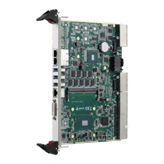
- Page 1 Series Value 6U CompactPCI® Intel® Xeon® E3, Core™ i7/i3 Processor Blade User’s Manual Manual Rev.: Revision Date: August 20, 2018 Part No: 50-15111-2000 Leading EDGE COMPUTING...
- Page 2 Leading EDGE COMPUTING Revision History Revision Release Date Description of Change(s) 2018-08-20 Preliminary release Revision History...
-
Page 3: Preface
Preface Copyright 2018 ADLINK Technology Inc. This document contains proprietary information protected by copy- right. All rights are reserved. No part of this manual may be repro- duced by any mechanical, electronic, or other means in any form without prior written permission of the manufacturer. - Page 4 Leading EDGE COMPUTING California Proposition 65 Warning WARNING: This product can expose you to chemicals including acrylamide, arsenic, benzene, cadmium, Tris(1,3-dichloro-2-propyl)phosphate (TDCPP), 1,4-Diox- ane, formaldehyde, lead, DEHP, styrene, DINP, BBP, PVC, and vinyl materials, which are known to the State of California to cause cancer, and acrylamide, benzene, cadmium, lead, mercury, phthalates, toluene, DEHP, DIDP, DnHP, DBP, BBP, PVC, and vinyl materials, which are known to the State of California to cause...
-
Page 5: Table Of Contents
cPCI-6636 Table of Contents Revision History..............ii Preface ..................iii List of Figures ............... vii List of Tables................ix 1 Introduction ................ 1 Overview................1 Features................2 Model Number Decoder............4 Package Contents ............... 5 2 Specifications ..............7 cPCI-6636(D) Processor Blade Specifications ....7 Block Diagrams.............. - Page 6 Leading EDGE COMPUTING cPCI-6636(D/DZ) Faceplate I/O......... 21 Connector Pin Assignments..........23 Switches and Buttons ............35 Important Safety Instructions..........41 Getting Service ..............43 Table of Contents...
-
Page 7: List Of Figures
Figure 4-1: cPCI-6636(D) Component Side Layout ......19 Figure 4-2: cPCI-6636D/DZ Assembly Layout ......... 20 Figure 4-3: cPCI-6636(D/DZ) Faceplate I/O ........21 Figure 4-4: cPCI-6636 Series Switch Locations - Component Side. 35 Figure 4-5: cPCI-6636 Series Switch Locations - Solder Side..36 List of Figures... - Page 8 Leading EDGE COMPUTING This page intentionally left blank. viii List of Figures...
-
Page 9: List Of Tables
cPCI-6636 List of Tables Table 2-1: cPCI-6636 Processor Blade Specifications ..... 7 Table 2-2: cPCI-6636(D/DZ) I/O Connectivity......... 11 Table 4-1: cPCI-6636(D) Front Panel System LED Descriptions ... 22 Table 4-2: LAN1/2 RJ-45 GbE Pin Definitions ........ 23 Table 4-3: LAN LED Status Definitions........... 23 Table 4-4: USB 3.0 Pin Definitions .......... - Page 10 Leading EDGE COMPUTING This page intentionally left blank. List of Tables...
-
Page 11: Introduction
Introduction 1.1 Overview The ADLINK cPCI-6636 Series is a 6U CompactPCI® processor blade based on the Intel® Xeon® E3 and 6th Generation Intel® Core™ i7/i3 Processors with Intel® HM170 or CM236 Chipsets. When paired with the Intel® CM236, the cPCI-6636 supports ECC memory. -
Page 12: Features
Moreover, the cPCI-6636 supports remote manageability by SEMA for system health monitoring over the Internet. The cPCI-6636 Series offers outstanding computing power from the latest Intel® processors and is an ideal solution for military, automation and other robust computing applications that require the highest computing power in a rugged, reliable CompactPCI system. - Page 13 cPCI-6636 cPCI-6636, cPCI-6636D support satellite mode operation in host and peripheral slots One PCIe x8 Gen3 XMC site on cPCI-6636D and cPCI-6636DZ Supports SEMA for system health monitoring 2x Gigabit Ethernet egress ports on faceplate provided by an Intel® I219LM and I210IT GbE controller via PCIe x1 and two additional Gigabit Ethernet ports Intel®...
-
Page 14: Model Number Decoder
Leading EDGE COMPUTING 1.3 Model Number Decoder c P C I-ET 663 6S L X X /6820 E /M X –X /X (A ) (C ) (D)(E)(F) (A) Operating Temperature Code Blank = 0°C to +60°C ET= -20°C to +70°C (for CPUs with TDP below 37W only) (B) Configuration Code Blank = cPCI-6636 single slot with I/O (DVI-I, COM, USB 3.0 x3, GbE x2), CFast slot, and J3/J5... -
Page 15: Package Contents
Please obtain authorization before returning any product to ADLINK. The packing contents of cPCI-6636 Series non-standard configurations will vary depending on customer requests. cPCI-6636(D) Processor Blade... - Page 16 Leading EDGE COMPUTING The contents of non-standard cPCI-6636 configurations may vary depending on the customer’s requirements. NOTE: NOTE: This product must be protected from static discharge and phys- ical shock. Never remove any of the components except at a static-free workstation. Use the anti-static bag shipped with the CAUTION: product when putting the board on a surface.
-
Page 17: Specifications
cPCI-6636 Specifications 2.1 cPCI-6636(D) Processor Blade Specifications CompactPCI® • PICMG® 2.0 CompactPCI® Rev. 3.0 Standards • PICMG® 2.1 Hot Swap Specification Rev. 2.0 • PICMG® 2.16 Packet Switching Backplane Rev. 1.0 Mechanical • Standard 6U CompactPCI® • Board size: 233mm x 160mm •... - Page 18 Leading EDGE COMPUTING Gigabit • One PCIe x1 Intel® I2199LM GbE PHY and two three PCIe Ethernet x1 Intel® I210IT Gigabit Ethernet controllers • Three Two egress 10/100/1000BASE-T ports on front panel, one supporting Intel® AMT 9.0 by I219LM PHY controller •...
- Page 19 cPCI-6636 Faceplate I/O cPCI-6636 (4HP) • 3x 10/100/1000BASE-T Ethernet ports • 1x DVI-I port & 1x DVI-D port • 3x USB 3.0 ports • 1x USB 2.0 port • 1x RJ-45 serial port supporting RS-232/422/485 cPCI-6636D (8HP) • 2x 10/100/1000BASE-T Ethernet ports •...
-
Page 20: Block Diagrams
Leading EDGE COMPUTING 2.2 Block Diagrams cPCI-6636(D/DZ) Blade DDR4-2133 soldered Front VGA (DZ) Front VGA (DZ) NXP PTN3355 NXP PTN3355 Up to 16GB Skylake-H Skylake-H Front DVI-I (DZ: VGA) Front DVI-I (DZ: VGA) DDR4-2133 SODIMM NXP PTN3355 NXP PTN3355 Up to 16GB Core i7 Core i7 1x DVI, PCIe x4... -
Page 21: I/O Connectivity Table
cPCI-6636 2.3 I/O Connectivity Table cPCI-6636 cPCI-6636D cPCI-6636DZ (4HP) (8HP) (8HP) Function Faceplate Onboard Faceplate Onboard Faceplate Onboard Y x2 Y x2 Y x2 Y x1 Y x1 Y x3 (RJ-45) (RJ-45) (RJ-45) USB 3.0 Y x3 Y x3 Y x8 DVI-I Y x1 Y x1... -
Page 22: Power Requirements
Leading EDGE COMPUTING 2.4 Power Requirements In order to guarantee a stable functionality of the system, it is rec- ommended to provide more power than the system requires. An industrial power supply unit should be able to provide at least twice as much power as the entire system requires of each voltage. -
Page 23: Functional Description
Functional Description The following sections describe the cPCI-6636 Series features and functions. 3.1 Processors The 6th Generation Intel® Core™ processor family is the state of art 64-bit, multi-core mobile processor built on 14 nanometer pro- cess technology. Based on the advanced microarchitecture, the processor is designed for a two-chip platform. - Page 24 Leading EDGE COMPUTING 1. The highest expected sustainable power while running known power intensive applications. TDP is not the maximum power that the processor can dissipate. 2. The maximum supported operating temperature. Supported Technologies Feature Xeon® E3-1505M v5 Core™ i7-6820EQ Core™ i3-6100E Intel®...
- Page 25 cPCI-6636 Feature Xeon® E3-1505M v5 Core™ i7-6820EQ Core™ i3-6100E Intel® Stable Image Platform Program (SIPP) Intel® Smart Response Technology Interfaces Two channels of DDR4-2133 ECC memory(cPCI-6636(D) only, Core™ i7 SKUs do not support ECC) Memory DDR4 data transfer rates of 2133 MT/s 64-bit wide channels DDR4 I/O Voltage of 1.2V 4Gb, and 8Gb DDR4 DRAM technologies are supported for...
-
Page 26: Chipset
Leading EDGE COMPUTING 3.2 Chipset The cPCI-6636(D) are equipped with Mobile Intel® CM236 Chip- set and cPCI-6636DZ is equipped with Mobile Intel® HM170 Chip- set. Functions and capabilities include: Feature Mobile Intel® CM236 Chipset Mobile Intel® HM170 Chipset Bus Speed 8 GT/s DMI3 8 GT/s DMI3 3.67 W... -
Page 27: Xmc
cPCI-6636 Feature Mobile Intel® CM236 Chipset Mobile Intel® HM170 Chipset Intel® Stable Image Platform Program (SIPP) Intel® Smart Sound Technology Intel® Trusted Execution Technology ‡ 3.3 XMC The cPCI-6636D/DZ supports one PCIe x8 XMC site for front panel I/O expansion. 3.4 Intel®... -
Page 28: Intel® Hyper-Threading Technology
Leading EDGE COMPUTING 3.5 Intel® Hyper-Threading Technology Intel® Hyper-Threading Technology allows an execution core to function as two logical processors. While some execution resources (such as caches, execution units, and buses) are shared, each logical processor has its own architectural state with its own set of general-purpose registers and control registers. -
Page 29: Board Interfaces
Board Interfaces This chapter illustrates the board layout, connector pin assignments, and jumper settings to familiarize users with the cPCI-6636 Series. 4.1 cPCI-6636(D) Component Side Layout SATA2 PCH1 SATA1 USB1 USB3 B2B_CONN1 USB5 COM1 SO_DIMM1 CF_CN1 CPU1 DVI1 CPU1 Intel®... -
Page 30: Cpci-6636D/Dz Assembly Layoutt
Leading EDGE COMPUTING 4.2 cPCI-6636D/DZ Assembly Layoutt SATA Drive Assembly DB-6636XMC XMC Adapter CPU Heatsink Figure 4-2: cPCI-6636D/DZ Assembly Layout... -
Page 31: Cpci-6636(D/Dz) Faceplate I/O
cPCI-6636 4.3 cPCI-6636(D/DZ) Faceplate I/O cPCI-6636 GbE x2 DVI-I USB 3.0 x3 Serial Port Reset Power LED Button HDD LED WDT LED cPCI-6636D USB 3.0 x3 GbE x2 Serial Port DVI-I Reset Power LED Button HDD LED WDT LED cPCI-6636DZ USB 3.0 x8 GbE x2 Power LED... -
Page 32: Table 4-1: Cpci-6636(D) Front Panel System Led Descriptions
Leading EDGE COMPUTING System LEDs Color Condition Indication System is off Power Green/ System Power ready (PWGD) Green Post OK No Watchdog event Orange Blinking Watchdog event alert No CF/CFast/SATA HDD activity Yellow Data read/write in process for CFast/ Blinking SATA drive Table 4-1: cPCI-6636(D) Front Panel System LED Descriptions... -
Page 33: Connector Pin Assignments
cPCI-6636 4.4 Connector Pin Assignments LAN1/2 RJ-45 GbE Connectors 10BASE-T/ Pin # 1000BASE-T 100BASE-TX LAN_TX0+ LAN_TX0- LAN_TX1+ — LAN_TX2+ — LAN_TX2- LAN_TX1- — LAN_TX3+ — LAN_TX3- Table 4-2: LAN1/2 RJ-45 GbE Pin Definitions Speed Activity Speed LED Activity LED Status (Green/Amber) (Yellow) Network link is not established... -
Page 34: Table 4-4: Usb 3.0 Pin Definitions
Leading EDGE COMPUTING USB 3.0 Connectors Pin # Signal Name Data- Data+ RX_N RX_P TX_N TX_P Table 4-4: USB 3.0 Pin Definitions cPCI-6636(D) COM1 (RJ-45) Pin # RS-232 RS-422 RS-485 DCD# Data- RTS# — — DSR# — — — Data+ —... -
Page 35: Table 4-7: Cpci-6636Dz Com1/2 Pin Definitions
cPCI-6636 cPCI-6636(D) COM RJ-45 to DB-9 Cable (PN: 30-01020-0200) Pin # RS-232 RS-422 RS-485 DCD# Data- Data+ — DTR#L — — — DSR# — — RTS# — — CTS# — — — — — Table 4-6: cPCI-6636(D) COM RJ-45 to DB-9 Cable Pin Definitions cPCI-6636DZ COM1-6 (RJ-45) The three RJ-45 ports on the cPCI-6636DZ carry two sets of RX/ TX signals each. -
Page 36: Table 4-8: Cpci-6636Dz Com3/4 Pin Definitions
Leading EDGE COMPUTING COM3/4 Pin # RS-232 COM3_RX COM3_TX COM4_RX COM4_TX Table 4-8: cPCI-6636DZ COM3/4 Pin Definitions COM5/6 Pin # RS-232 COM3_RX COM3_TX COM4_RX COM4_TX Table 4-9: cPCI-6636DZ COM5/6 Pin Definitions... -
Page 37: Table 4-10: Cpci-6636Dz Com Rj-45 To 2X Db-9 Cable Pin Definitions
cPCI-6636 cPCI-6636DZ COM RJ-45 to 2x DB-9 Cable (PN: 30-25044-1020) The DB-9 connectors are labeled “01” and “02”. Connector “01” corresponds to the odd numbered COM signal on the RJ-45 con- nector, and connector “02” corresponds to the even numbered COM signal (i.e. -
Page 38: Table 4-11: Dvi-I Connector Pin Definition
Leading EDGE COMPUTING DVI-I Connector Pin # Signal Pin # Signal TMDS Data2- Hot Plug Detect TMDS Data2+ TMDS Data0- TMDSData0+ DDC Clock [SCL] DDC Data [SDA] Analog vertical sync TMDS Clock + TMDS Data1- TMDS Clock - TMDS Data1+ Analog Red Analog Green Analog Blue... -
Page 39: Table 4-12: Serial Ata 7-Pin Connector Pin Definition
cPCI-6636 Serial ATA 7-pin Connector (SATA1) Pin # Signal Table 4-12: Serial ATA 7-pin Connector Pin Definition Serial ATA Connector with Power 2.5” SATA adapter board (PN: 59-37571-0000) Pin # Signal Signal Power P13~P15 Table 4-13: Serial ATA Connector with power Pin Definition... -
Page 40: Table 4-14: Cfast Socket Pin Definition
Leading EDGE COMPUTING CFast Socket DB-CFAST adapter board (PN: 59-37572-0000) Pin # Signal Name Ground SATA_TX-P SATA_TX-N Ground SATA_RX-N SATA_RX-P Ground CFast_CDI Ground Ground CFast_LED1 CFast_LED2 +3.3V +3.3V Ground Ground CFast_CDO Table 4-14: CFast Socket Pin Definition... -
Page 41: Table 4-15: Compactpci J1 Connector Pin Definition
cPCI-6636 CompactPCI J1 Connector CPCI_REQ64-L CPCI_ENUM-L P3V3 CPCI_AD1 CPCI_VIO_STB CPCI_ACK64-L GND P3V3 CPCI_AD4 CPCI_AD3 CPCI_AD2 CPCI_AD7 P3V3 CPCI_AD6 CPCI_AD5 P3V3 CPCI_AD9 CPCI_AD8 CPCI_M66EN CPCI_CBE-L0 GND CPCI_AD12 CPCI_VIO_STB CPCI_AD11 CPCI_AD10 P3V3 CPCI_AD15 CPCI_AD14 CPCI_AD13 CPCI_SERR-L P3V3 CPCI_PAR CPCI_CBE-L1 GND P3V3 IPMB_CLK IPMB_DAT CPCI_PERR-L GND GND CPCI_DEVSEL-L... -
Page 42: Table 4-16: Compactpci J2 Connector Pin Definition
Leading EDGE COMPUTING CompactPCI J2 Connector CPCI_CLK6 CPCI_CLK5 IPMB_DAT IPMB_CLK IPMB_PWR J2_RST-L CPCI_REQ-L6 CPCI_GNT-L6 GND CPCI_DEG-L CPCI_FAL-L CPCI_REQ-L5 CPCI_GNT-L5 GND CPCI_AD35 CPCI_AD34 CPCI_AD33 CPCI_AD32 CPCI_AD38 CPCI_VIO CPCI_AD37 CPCI_AD36 CPCI_AD42 CPCI_AD41 CPCI_AD40 CPCI_AD39 CPCI_AD45 CPCI_VIO CPCI_AD44 CPCI_AD43 CPCI_AD49 CPCI_AD48 CPCI_AD47 CPCI_AD46 CPCI_AD52 CPCI_VIO CPCI_AD51... -
Page 43: Table 4-17: Compactpci J3 Connector Pin Definition
cPCI-6636 CompactPCI J3 Connector P12V GND LAN4_MDI0_P LAN4_MDI0_N LAN4_MDI2_P LAN4_MDI2_N GND GND LAN4_MDI1_P LAN4_MDI1_N LAN4_MDI3_P LAN4_MDI3_N GND GND LAN3_MDI0_P LAN3_MDI0_N LAN3_MDI2_P LAN3_MDI2_N GND GND LAN3_MDI1_P LAN3_MDI1_N LAN3_MDI3_P LAN3_MDI3_N GND USB_OC5-L USB_OC6-L USB_OC7-L USB_OC8-L USB_OC9-L USB8-P USB8-N USB9-P USB9-N USB6-P USB6-N USB7-P USB7-N USB4-P... -
Page 44: Table 4-18: Compactpci J5 Connector Pin Definition
Leading EDGE COMPUTING CompactPCI J5 Connector 22 GND LAN2_MDI_P0 LAN2_MDI_N0 LAN2_MDI_P2 LAN2_MDI_N2 GND 21 GND LAN2_MDI_P1 LAN2_MDI_N1 LAN2_MDI_P3 LAN2_MDI_N3 GND 20 GND LAN1_MDI_P0 LAN1_MDI_N0 LAN1_MDI_P2 LAN1_MDI_N2 GND 19 GND LAN1_MDI_P1 LAN1_MDI_N1 LAN1_MDI_P3 LAN1_MDI_N3 GND 18 GND DVID_CLKP DVID_CLKN 17 GND DVID_TXP1 DVID_TXN1 COM2_TX... -
Page 45: Switches And Buttons
4.5 Switches and Buttons Figure 4-4: cPCI-6636 Series Switch Locations - Component Side... -
Page 46: Figure 4-5: Cpci-6636 Series Switch Locations - Solder Side
Leading EDGE COMPUTING Figure 4-5: cPCI-6636 Series Switch Locations - Solder Side... - Page 47 cPCI-6636 VGA Signal Front/Rear Switch (SW1 Pin 1, Reserved) VGA functionality is controlled by BIOS. BIOS Protection Switch (SW1 Pin 2) Enabling BIOS protection prevents changes to be made to the BIOS settings (enabled by default). SW1 Pin Reserved Reserved (default) BIOS Protection Enabled BIOS Protection Disabled (default)
- Page 48 Leading EDGE COMPUTING COM1 Mode Switch (SW4) cPCI-6636(D) only. Function 1 OFF, 2 ON (default) RS-232 1 ON, 2 OFF RS-485 1 ON, 2 ON RS-422 OFF (Reserved) OFF (Reserved) System Reset Button (SW5) Press switch SW5 to reset the system.
- Page 49 cPCI-6636 Force Ejector Handle Closed Switch (SW6) Switch SW6 allows the ejector handle state to be forced "closed" so that blades without ejector handles (e.g. conduction cooled) will power on when inserted into the chassis. Force the ejector handle On/Off state is controlled state to "closed"...
- Page 50 Leading EDGE COMPUTING This page intentionally left blank.
-
Page 51: Important Safety Instructions
cPCI-6636 Important Safety Instructions For user safety, please read and follow all instructions, WARNINGS, CAUTIONS, and NOTES marked in this manual and on the associated equipment before handling/operating the equipment. Read these safety instructions carefully. Keep this user’s manual for future reference. Read the specifications section of this manual for detailed information on the operating environment of this equipment. - Page 52 Leading EDGE COMPUTING Never attempt to fix the equipment. Equipment should only be serviced by qualified personnel. A Lithium-type battery may be provided for uninterrupted, backup or emergency power. Risk of explosion if battery is replaced with one of an incorrect type.
-
Page 53: Getting Service
San Jose, CA 95138, USA Tel: +1-408-360-0200 Toll Free: +1-800-966-5200 (USA only) Fax: +1-408-360-0222 Email: info@adlinktech.com ADLINK Technology (China) Co., Ltd. 300 Fang Chun Rd., Zhangjiang Hi-Tech Park Pudong New Area, Shanghai, 201203 China Tel: +86-21-5132-8988 Fax: +86-21-5132-3588 Email: market@adlinktech.com...
Need help?
Do you have a question about the cPCI-6636 Series and is the answer not in the manual?
Questions and answers