
Related Manuals for ADLINK Technology cPCIS-6400U Series


Summary of Contents for ADLINK Technology cPCIS-6400U Series
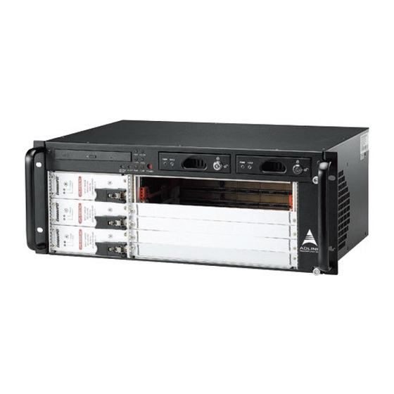
- Page 1 cPCIS-6400U/6400X Series 4U Height Subsystem for 6U cPCI and Components User’s Manual Manual Rev. 2.01 Revision Date: December 21, 2006 Part No: 50-15044-2000 Advance Technologies; Automate the World.
- Page 2 Copyright 2005 ADLINK TECHNOLOGY INC. All Rights Reserved. The information in this document is subject to change without prior notice in order to improve reliability, design, and function and does not represent a commitment on the part of the manufacturer.
- Page 3 Getting Service from ADLINK Customer Satisfaction is top priority for ADLINK Technology Inc. Please contact us should you require any service or assistance. ADLINK TECHNOLOGY INC. Web Site: http://www.adlinktech.com Sales & Service: Service@adlinktech.com TEL: +886-2-82265877 FAX: +886-2-82265717 Address: 9F, No. 166, Jian Yi Road, Chungho City,...
-
Page 5: Table Of Contents
Boards Space ..............2 CompactPCI Compliancy ..........2 Enclosure ................ 2 Specifications............... 3 Mechanical Layout............... 4 cPCIS-6400U Series (redundant PSU) ......4 cPCIS-6400X Series (ATX PSU) ........5 Compatible CPU Modules ........... 7 Customized Systems ............7 2 Getting Started ..............9 Shipping Contents ............... - Page 6 cBP-3063 CompactPCI Power Backplane......49 Specifications ..............49 Mechanical Drawing ............. 50 Connector Pin Assignments ......... 51 4 Cooling System..............55 System Alarm Board ............56 Fan Alarm ................57 Fan Removal and Replacement Procedure (cPCIS-6400U only)........57 Air Filter Replacement (cPCIS-6400U only)........
-
Page 7: List Of Figures
Figure 2-5: Hard drive rack keylock positions ......13 Figure 2-6: Remove the hard drive rack from the drive bay..14 Figure 2-7: cPCIS-6400U Series switches and LEDs....15 Figure 2-8: cPCIS-6400X Series switches and LEDs ....16 Figure 3-1: cBP-6105R Backplane Front View ......19 Figure 3-2: cBP-6105R Backplane Rear View...... -
Page 9: Introduction
Introduction The cPCIS-6400U/6400X Series subsystems are designed for 6U cPCI boards with 80mm RTMs. The chassis is 4U in height and standard 19” rack mount width. The cPCIS-6400U provides 2+1 hot swappable 500W+250W redundant power supplies with universal AC input, while the cPCIS-6400X has a built-in 400W AC-input ATX power supply with cooling fan. -
Page 10: Boards Space
Guarded power switch and reset button Voltage LEDs allow convenient monitoring: +12V, -12V, +5V, +3.3V Suitable for both rackmount and benchtop applications Built-in alarm module to monitor chassis temperature, fan status. Comprehensive EMC shielding: EMC gaskets are installed on top and bottom edges of both front and rear panel aper- tures Boards Space Board space supports standard 6U height and 6-slot width... -
Page 11: Specifications
1.2 Specifications CompactPCI Standards PICMG 2.0; 2.1; 2.5; 2.9; 2.11 Form Factor 6U cPCI with 80 mm depth rear I/O EIA RS-310C 19" 9U high rack-mount enclosure Enclosure Coated metal plate outer covering Guarded power switch and reset button Monitors inner chassis temperature & fan status (model dependent) Basic Alarm Module Abnormal status will generate alarm and LED warning... -
Page 12: Mechanical Layout
1.3 Mechanical Layout cPCIS-6400U Series (redundant PSU) Figure 1-1: cPCIS-6400U Front View Figure 1-2: cPCIS-6400U Rear View Introduction... -
Page 13: Cpcis-6400X Series (Atx Psu)
cPCIS-6400X Series (ATX PSU) Figure 1-3: cPCIS-6400X Front View Figure 1-4: cPCIS-6400X Rear View Introduction... -
Page 14: Figure 1-5: Cpcis-6400 Series Top View
cPCIS-6400 Series External Dimensions (mm) Figure 1-5: cPCIS-6400 Series Top View Figure 1-6: cPCIS-6400 Series Left Side View Introduction... -
Page 15: Compatible Cpu Modules
1.4 Compatible CPU Modules For complete systems, users must order CPU modules in addition to the sub-system. The following table lists which ADLINK Com- pactPCI CPU modules are compatible with the cPCIS-6400 Series models. CPU Module 32-bit/33MHz 64-bit/66MHz cPCI-6860A — cPCI-6840 —... - Page 16 Introduction...
-
Page 17: Getting Started
Getting Started This chapter describes the unpacking procedure of the sub-sys- tem and installation procedures for CompactPCI boards and power supply units (PSUs), and hard drive rack operation proce- dures. 2.1 Shipping Contents Check the shipping carton for any damage. If the shipping carton and contents are damaged, please notify the dealer for a replace- ment. -
Page 18: Figure 2-1: Installing A 6U Sbc Module
The handles on CompactPCI cards and PSUs ensure simple and safe installation and removal. Please follow the procedures below to install a CompactPCI module into a chassis: 1. Place the sub-system on a level surface or rackmount it. Remove the blanking plates where required by undoing the retaining screws at each end. -
Page 19: Rear Transition Module Installation/Removal
4. Continue inserting the card until the handles engage with the chassis. 5. Pull inwards on the handles for final insertion. Ensure that the red buttons on the handles fully latch into posi- tion as unless this is done the card is not correctly inserted. -
Page 20: Power Supply Unit Replacement
2.4 Power Supply Unit Replacement (cPCIS-6400U only) The cPCIS-6400U series subsystems come with cPS-H325 PSUs pre-installed. The removal and installation procedures for PSUs are the same as for CompactPCI cards, except there is only one handle. To replace a PSU module, refer to the figures and instruc- tions below. -
Page 21: Hard Drive Racks
2. Pull outwards to remove the PSU. Figure 2-4: Pull outwards to remove the PSU 3. Insert the new PSU module, push on the handle until it latches into position, and replace the retaining screws. 2.5 Hard Drive Racks The cPCI-6400U and cPCIS-6400X subsystems have two hard drive racks for 3.5”... -
Page 22: Rack Insertion And Removal
2. Lift the rack handle outwards and pull the hard drive rack out of the drive bay. Figure 2-6: Remove the hard drive rack from the drive bay 3. Insert the hard drive into the rack and secure with screws as per standard hard drive installation procedure. 4. -
Page 23: Powering Up The System
(such as a pen) to actuate the power switch and reset button. Voltage LEDs allow convenient monitoring of the power supply. Refer to the diagrams below for LED and switch locations. cPCIS-6400U Series (redundant PSU) Figure 2-7: cPCIS-6400U Series switches and LEDs Getting Started... -
Page 24: Figure 2-8: Cpcis-6400X Series Switches And Leds
cPCIS-6400X Series (ATX PSU) Figure 2-8: cPCIS-6400X Series switches and LEDs Getting Started... -
Page 25: Backplanes
In this chapter, we will describe the backplanes for the cPCIS- 6400U/6400X Series. The following table outlines the backplanes that correspond to each model. Model Type Backplane cPCIS-6400U/32 32-bit/33MHz cBP-6105R cPCIS-6400X/32 cPCIS-6400U/64 64-bit/66MHz cBP-6405R cPCIS-6400X/64 The cPCIS-6400U Series models use the cBP-3063 CompactPCI Power Backplane. Backplanes... -
Page 26: Cbp-6105R (32-Bit/33Mhz)
3.1 cBP-6105R (32-bit/33MHz) The backplane for the cPCIS-6400 Series 6U 32-bit, 5-slot chassis is the cBP-6105R, a 6U 5-slot H.110 32-bit CompactPCI back- plane with rear I/O. Features Standard CompactPCI 3U height for 6U cPCI cards Supports 80mm rear I/O for each slot Suitable for one single/dual-slot system module and four expansion cards Supports PICMG 2.5 H.110 CT Bus... -
Page 27: Mechanical Drawing
Mechanical Drawing Figure 3-1: cBP-6105R Backplane Front View Figure 3-2: cBP-6105R Backplane Rear View Backplanes... -
Page 28: Connector Pin Assignments
Connector Pin Assignments ATX Power Connector [CN1] Signal Signal +3.3V +3.3V +3.3V -12V PS_ON_L PWRGOOD STB5V +12V Power LED Connector [JP2] Signal Signal +12V -12V +3.3V SM Bus Connector [JP3] Signal DATA V(I/O) ALERT# Backplanes... - Page 29 H.110 DC Power Connector [CN6] Signal -SEL Vbat SEL VbatRtn VRGRtn -Vbat VbatRtn RST# Connector [J1] Signal PRSTA# FAL# Connector [J2] Signal FAL# INH# Connector [J3] Signal INH# Backplanes...
- Page 30 System Slot: [1–P1] REQ64# ENUM# +3.3V AD[1] V(I/O) AD[0] ACK64# GND +3.3V AD[4] AD[3] AD[2] AD[7] +3.3V AD[6] AD[5] +3.3V AD[9] AD[8] M66EN C/BE[0]# GND AD[12] V(I/O) AD[11] AD[10] +3.3V AD[15] AD[14] AD[13] SERR# +3.3V C/BE[1]# GND +3.3V IPMB_SCL IPMB_SDA PERR# DEVSEL# V(I/O)
- Page 31 System Slot: [1–P2] CLK6 Reserved Reserved Reserved CLK5 Reserved Reserved SMDATA SMCLK ALERT# Reserved Reserved Reserved Reserved Reserved PRST# REQ6# GNT6# Reserved Reserved DEG# Reserved Reserved FAL# REQ5# GNT5# Reserved Reserved Reserved Reserved Reserved V(I/O) Reserved Reserved Reserved Reserved Reserved Reserved Reserved V(I/O)
- Page 32 System Slot: [1–P3] Reserved Reserved Reserved Reserved Reserved Reserved Reserved Reserved Reserved Reserved Reserved Reserved Reserved Reserved Reserved Reserved Reserved Reserved Reserved Reserved Reserved Reserved Reserved Reserved Reserved Reserved Reserved Reserved Reserved Reserved Reserved Reserved Reserved Reserved Reserved Reserved Reserved Reserved Reserved Reserved...
- Page 33 System Slot: [1–P4] Reserved Reserved Reserved Reserved Reserved Reserved Reserved Reserved Reserved Reserved Reserved Reserved Reserved Reserved Reserved Reserved Reserved Reserved Reserved Reserved Reserved Reserved Reserved Reserved Reserved Reserved Reserved Reserved Reserved Reserved Reserved Reserved Reserved Reserved Reserved Reserved Reserved Reserved Reserved Reserved...
- Page 34 System Slot: [1–P5] Reserved Reserved Reserved Reserved Reserved Reserved Reserved Reserved Reserved Reserved Reserved Reserved Reserved Reserved Reserved Reserved Reserved Reserved Reserved Reserved Reserved Reserved Reserved Reserved Reserved Reserved Reserved Reserved Reserved Reserved Reserved Reserved Reserved Reserved Reserved Reserved Reserved Reserved Reserved Reserved...
- Page 35 Peripheral Slot: [2–P1] - [5–P1] REQ64# ENUM# +3.3V AD[1] V(I/O) AD[0] ACK64# GND +3.3V AD[4] AD[3] AD[2] AD[7] +3.3V AD[6] AD[5] +3.3V AD[9] AD[8] M66EN C/BE[0]# GND AD[12] V(I/O) AD[11] AD[10] +3.3V AD[15] AD[14] AD[13] SERR# +3.3V C/BE[1]# GND +3.3V IPMB_SCL IPMB_SDA PERR#...
- Page 36 Peripheral Slot: [2–P2] - [5–P2] Reserved Reserved Reserved Reserved Reserved Reserved Reserved Reserved Reserved Reserved Reserved Reserved Reserved Reserved Reserved Reserved Reserved Reserved Reserved Reserved Reserved Reserved Reserved Reserved Reserved Reserved AD[35] AD[34] AD[33] AD[32] AD[38] V(I/O) AD[37] AD[36] AD[42] AD[41] AD[40] AD[39]...
- Page 37 Peripheral Slot: [2–P3] - [5–P3] Reserved Reserved Reserved Reserved Reserved Reserved Reserved Reserved Reserved Reserved Reserved Reserved Reserved Reserved Reserved Reserved Reserved Reserved Reserved Reserved Reserved Reserved Reserved Reserved Reserved Reserved Reserved Reserved Reserved Reserved Reserved Reserved Reserved Reserved Reserved Reserved Reserved Reserved...
- Page 38 Peripheral Slot: [2–P4] - [5–P4] SGA4 SGA3 SGA2 SGA1 SGA0 +12V Reserved CT_EN# -12V CT_MC PFS0# CT_RESET Reserved Reserved Reserved GND -SELVbat PFS1# Reserved Reserved -SELVbat Rtn No Pin No Pin No Pin No Pin No Pin No Pin No Pin No Pin No Pin No Pin...
- Page 39 Peripheral Slot: [2–P5] - [5–P5] Reserved Reserved Reserved Reserved Reserved Reserved Reserved Reserved Reserved Reserved Reserved Reserved Reserved Reserved Reserved Reserved Reserved Reserved Reserved Reserved Reserved Reserved Reserved Reserved Reserved Reserved Reserved Reserved Reserved Reserved Reserved Reserved Reserved Reserved Reserved Reserved Reserved Reserved...
- Page 40 IDE Add-on Card: [0–P3] +12V +12V +12V GND PPWRGD PDCS16# PIORDY AP3D19 PIRQ GND PDACT# AP3B18 PCS3# PCS1# PPDIAG GND PDD15 PDD14 PDD13 PDD12 AP3E17 GND PDD11 PDD10 PDD9 PDD8 DDAK0# GND PDA0 PDA1 PDA2 DDRQ0 PDD7 PDD6 PDD5 PDD4 DIOW0# GND PDD3 PDD2...
-
Page 41: Jumper Settings
Jumper Settings Shelf Enumeration Bus Signals [JP1] - (default: 1-2 shorted) Column 1 Column 2 Column 3 SGA0 SGA1 SGA2 SGA3 SGA4 V(I/O) Setting Jumper [J4 - J6] - (default: J4-J5 shorted) Signal V(I/O) +3.3V Backplanes... -
Page 42: Cbp-6405R (64-Bit/66Mhz)
3.2 cBP-6405R (64-bit/66MHz) The backplane for the cPCIS-6400 Series 6U 64-bit, 5-slot chassis is the cBP-6405R, a 6U 64-bit, 5-slot, H.110 CompactPCI back- plane with rear I/O. Features Standard CompactPCI 3U height for 6U cPCI cards Supports 80mm rear I/O for each slot Suitable for one single/dual-slot system module and four expansion cards Supports PICMG 2.5 H.110 CT Bus... -
Page 43: Mechanical Drawing
Mechanical Drawing Figure 3-3: cBP-6405R Backplane Front View Figure 3-4: cBP-6405R Backplane Rear View Backplanes... -
Page 44: Connector Pin Assignments
Connector Pin Assignments ATX Power Connector [CN1, CN3] Signal Signal +3.3V +3.3V +3.3V -12V PS_ON_L PWRGOOD STB5V +12V Power LED Connector [JP2] Signal Signal +12V -12V +3.3V SM Bus Connector [JP3] Signal DATA V(I/O) ALERT# Backplanes... - Page 45 H.110 DC Power Connector [CN6] Signal -SEL Vbat SEL VbatRtn VRGRtn -Vbat VbatRtn RST# Connector [J1] Signal PRSTA# FAL# Connector [J2] Signal FAL# INH# Connector [J3] Signal INH# Backplanes...
- Page 46 System Slot: [1–P1] REQ64# ENUM# +3.3V AD[1] V(I/O) AD[0] ACK64# GND +3.3V AD[4] AD[3] AD[2] AD[7] +3.3V AD[6] AD[5] +3.3V AD[9] AD[8] M66EN C/BE[0]# GND AD[12] V(I/O) AD[11] AD[10] +3.3V AD[15] AD[14] AD[13] SERR# +3.3V C/BE[1]# GND +3.3V IPMB_SCL IPMB_SDA PERR# DEVSEL# V(I/O)
- Page 47 System Slot: [1–P2] CLK6 Reserved Reserved Reserved CLK5 Reserved Reserved SMDATA SMCLK ALERT# Reserved Reserved Reserved Reserved Reserved PRST# REQ6# GNT6# Reserved Reserved DEG# Reserved Reserved FAL# REQ5# GNT5# AD[35] AD[34] AD[33] AD[32] AD[38] V(I/O) AD[37] AD[36] AD[42] AD[41] AD[40] AD[39] AD[45] V(I/O)
- Page 48 System Slot: [1–P3] Reserved Reserved Reserved Reserved Reserved Reserved Reserved Reserved Reserved Reserved Reserved Reserved Reserved Reserved Reserved Reserved Reserved Reserved Reserved Reserved Reserved Reserved Reserved Reserved Reserved Reserved Reserved Reserved Reserved Reserved Reserved Reserved Reserved Reserved Reserved Reserved Reserved Reserved Reserved Reserved...
- Page 49 System Slot: [1–P4] Reserved Reserved Reserved Reserved Reserved Reserved Reserved Reserved Reserved Reserved Reserved Reserved Reserved Reserved Reserved Reserved Reserved Reserved Reserved Reserved Reserved Reserved Reserved Reserved Reserved Reserved Reserved Reserved Reserved Reserved Reserved Reserved Reserved Reserved Reserved Reserved Reserved Reserved Reserved Reserved...
- Page 50 System Slot: [1–P5] Reserved Reserved Reserved Reserved Reserved Reserved Reserved Reserved Reserved Reserved Reserved Reserved Reserved Reserved Reserved Reserved Reserved Reserved Reserved Reserved Reserved Reserved Reserved Reserved Reserved Reserved Reserved Reserved Reserved Reserved Reserved Reserved Reserved Reserved Reserved Reserved Reserved Reserved Reserved Reserved...
- Page 51 Peripheral Slot: [2–P1] - [5–P1] REQ64# ENUM# +3.3V AD[1] V(I/O) AD[0] ACK64# GND +3.3V AD[4] AD[3] AD[2] AD[7] +3.3V AD[6] AD[5] +3.3V AD[9] AD[8] M66EN C/BE[0]# GND AD[12] V(I/O) AD[11] AD[10] +3.3V AD[15] AD[14] AD[13] SERR# +3.3V C/BE[1]# GND +3.3V IPMB_SCL IPMB_SDA PERR#...
- Page 52 Peripheral Slot: [2–P2] - [5–P2] Reserved Reserved Reserved Reserved Reserved Reserved Reserved Reserved Reserved Reserved Reserved Reserved Reserved Reserved Reserved Reserved Reserved Reserved Reserved Reserved Reserved Reserved Reserved Reserved Reserved Reserved AD[35] AD[34] AD[33] AD[32] AD[38] V(I/O) AD[37] AD[36] AD[42] AD[41] AD[40] AD[39]...
- Page 53 Peripheral Slot: [2–P3] - [5–P3] Reserved Reserved Reserved Reserved Reserved Reserved Reserved Reserved Reserved Reserved Reserved Reserved Reserved Reserved Reserved Reserved Reserved Reserved Reserved Reserved Reserved Reserved Reserved Reserved Reserved Reserved Reserved Reserved Reserved Reserved Reserved Reserved Reserved Reserved Reserved Reserved Reserved Reserved...
- Page 54 Peripheral Slot: [2–P4] - [5–P4] SGA4 SGA3 SGA2 SGA1 SGA0 +12V Reserved CT_EN# -12V CT_MC PFS0# CT_RESET Reserved Reserved Reserved GND -SELVbat PFS1# Reserved Reserved -SELVbat Rtn No Pin No Pin No Pin No Pin No Pin No Pin No Pin No Pin No Pin No Pin...
- Page 55 Peripheral Slot: [2–P5] - [5–P5] Reserved Reserved Reserved Reserved Reserved Reserved Reserved Reserved Reserved Reserved Reserved Reserved Reserved Reserved Reserved Reserved Reserved Reserved Reserved Reserved Reserved Reserved Reserved Reserved Reserved Reserved Reserved Reserved Reserved Reserved Reserved Reserved Reserved Reserved Reserved Reserved Reserved Reserved...
-
Page 56: Jumper Settings
Jumper Settings Shelf Enumeration Bus Signals [JP1] - (default: 1-2 shorted) Column 1 Column 2 Column 3 SGA0 SGA1 SGA2 SGA3 SGA4 PCI 33/66MHz Select [JP5] Signal M66EN Settings: shorted 33MHz, open 66MHz – default: open V(I/O) Setting Jumper [J4 - J6] - (default: J4-J5 shorted) Signal V(I/O) +3.3V... -
Page 57: Cbp-3063 Compactpci Power Backplane
3.3 cBP-3063 CompactPCI Power Backplane The power backplane for the cPCIS-6400U 5-slot chassis is the cBP-3063. Specifications PICMG 2.11 3U CompactPCI 47-pin Power Backplane Dimension: 120.92 x 128.7 (mm, W x H) Power Module Sockets: three DC output (ATX connector): three Cascading Current Sharing Cascading Voltage Sense: Dedicated voltage sense con- nector... -
Page 58: Mechanical Drawing
Mechanical Drawing Figure 3-5: cBP-3063 Power Backplane Front View Figure 3-6: cBP-3063 Power Backplane Rear View Backplanes... -
Page 59: Connector Pin Assignments
Connector Pin Assignments CompactPCI 47-Pin PSU Connector: Power 1-3 [CN1-CN3] Signal Signal ACL/-DC IN ACN/+DC IN V1 SENSE CGND V1ADJ V3 SHARE IPMB_PWR +FAL# RESERVED V2 SHARE IPMB_SDA INH# RESERVED DEG# IPMB_SCL V3 SENSE V1 SHARE S RTN 13-18 V2 SENSE 5-12 V2ADJ AC-Inlet Connector [CN4]... - Page 60 IPMB Connector [CN5] Signal DATA V(I/O) ALERT# Power Sense Connector [CN6, CN7] Signal Ground +3.3V -12V +12V Current Share Connector [CN8, CN9] Signal Ground +3.3V -12V +12V Backplanes...
- Page 61 DC Power Out [CN10, CN11, C12]) Signal Signal +3.3V +3.3V +3.3V -12V INH# FAL# DEG# +12V INH#1 Connector [J1] Signal INH#1 INH#2 Connector [J2] Signal INH#2 INH#3 Connector [J3] Signal INH#3 Backplanes...
- Page 62 DEG#/FAL# Connector [J5] Signal DEG#1 FAL#1 RSV23A RSV26A DEG#2 FAL#2 RSV23B RSV26B DEG#3 FAL#3 RSV23C RSV26C INH# Connector [J5] Signal INH# Backplanes...
-
Page 63: Cooling System
Cooling System The cPCIS-6400U/X Series subsystems are equipped with several fans to provide cooling for the system board, peripheral cards and power supply units. There is one front-access intake fan at the right side of the chassis with a replaceable air filter. Two small exhaust fans are at the top rear of the chassis, and one large fan provides exhaust at the left rear for the power supply units. -
Page 64: System Alarm Board
4.1 System Alarm Board Supports fault alarm for up to 8 fans. If any fan faults, the Fan LED will flash and an audible alarm will sound Can detect temperature at two different locations. Trigger temperature for each sensor can be set indepen- dently (50°C, 60°C, 70°C - default 50 °C). -
Page 65: Fan Alarm
4.2 Fan Alarm The embedded alarm board monitors temperature & fan status. Should a fan become disabled, the Fan LED will light up and an audible warning will be heard. To disable the audible warning, press the Alarm Reset button. The Fan LED will continue to flash until the faulty fan is replaced. -
Page 66: Figure 4-3: Remove The Front-Access Intake Fan Module
front-access intake Figure 4-3: Remove the fan module Rear Exhaust Fans (small) 1. Loosen the screws attaching the rear exhaust fan mod- ule (small) at the top rear of the chassis. 2. Pull the fan module out, disconnect the power cable, and replace with a functional fan module. -
Page 67: Figure 4-4: Remove The Rear Exhaust Fan Module (Small)
Figure 4-4: Remove the rear exhaust fan module (small) Rear Exhaust Fan (PSU) 1. Loosen the screws attaching the rear exhaust fan mod- ule (PSU) at the right rear of the chassis as shown below. Figure 4-5: Remove the rear exhaust fan module (PSU) Cooling System... -
Page 68: Figure 4-6: Disconnect The Rear Exhaust Fan Module (Psu) Power Ca
2. Pull the fan module out, disconnect the power cable, and replace with a functional fan module. Figure 4-6: Disconnect the rear exhaust fan module (PSU) power cable 3. Reverse steps 1-2 to replace the fan module. Left-Side Exhaust Fan 1. -
Page 69: Air Filter Replacement
2. Lift the fan module out of the chassis from the bottom edge, disconnect the power cables, and replace with a functional fan module. Figure 4-8: Remove the left exhaust fan module and disconnect the power cables 3. Reverse steps 1-2 to replace the fan module. For replacement fan modules, please contact your ADLINK distributor. -
Page 70: Figure 4-9: Air Filter Removal And Replacement
Air Filter Removal and Replacement Procedure 1. Remove the front-access intake fan module as shown in Figure 4.3 above. 2. Lay the fan module on its side, remove the four screws securing the filter cover, and lift the cover to expose the filter element. -
Page 71: Temperature Alarm
4.5 Temperature Alarm When the subsystem’s internal temperature exceeds 50°C, the TEMP LED will flash and an audible warning will be heard (see Figure 5.2 above for LED location). To reset the alarm and disable the audible warning, press the Alarm Reset button. In order to protect the system from damage resulting from over- heating, it should be shut down immediately. - Page 72 SUNON KD1209PFV1 (rear PSU exhaust fan) Dimensions: 92 x 92 x 25mm Weight: 123 g Type: 12V DC brush-less, with ball bearing motor Rated voltage: 12V @ 0.23A Rated power: 2.8 W/each Fan speed: 3600RPM Maximum Air flow: 51 CFM/each (when zero static pres- sure) Noise: 37 dBA/each SUNON KD1204PFV1 (left side fan module fans x4)
-
Page 73: Power Supply Unit
Power Supply Unit The power supply options for the cPCIS-6400 Series are as fol- lows: The cPCIS-6400U Series is equipped with ADLINK’s cPS- H325/AC CompactPCI power module and the cPCIS-6400X Series is equipped with the APS940XA ATX power supply. 5.1 cPCIS-6400U: cPS-H325/AC Features PICMG 2.11 CompactPCI power interface compliant... -
Page 74: Input Characteristics
Input Characteristics Input Voltage: Typ. 90 - 264 VAC Power Factor Correction: Meets Harmonic Correction IEC1000-3-2. Power Factor typ. 0.95-0.97 Input Connector: Positronic 47-pin PCIH47M400A1 Input Frequency: 47-63Hz Inrush Current: Less than 30A @ 230VAC Input Current: 2.8A @115VAC / 1.4A @230VAC Dielectric Withstand: Meets IEC950 regulations EMI: Meets EN55022 / FCC Class A Hold-up Time: 5mS after power fail signal... - Page 75 Properties 1: OVP built-in 2: Adjustable 3: Remote sensing 4: 3rd-wire Load Sharing 5: Droop Current Sharing 6: Installed with Or-ing diode 7: Magnetic Amplifier 8: Installed with Post-regulator 9: Common Choke Remarks Peak load sustainable for less than 60sec. with duty cycle <10%.
-
Page 76: Cpcis-6400X: Aps940Xa Atx 400W
5.2 cPCIS-6400X: APS940XA ATX 400W Features Active PFC (full range) 12V Max. Current : 30A Noise & Thermal Control Specifications Operating Temperature Range: -10°C – 40°C Cooling: one 80mm DC fan Active Power Factor Correction meets IEC-1000-3-2 CLASS D Dimensions: 140.00x150.00x86.00 (mm) Hold Up Time: 16 ms minimum at full load &... -
Page 77: Output Characteristics
Output Characteristics Output Current(A) Regulation Output Output Ripple& Noise Voltage MIN. MAX. PEAK LOAD LINE Max[P-P] – ± 5% ± 1% 50mV – +7 – -5% ± 1% 120mV – ± 5% ± 1% 150mV -12V – ± 5% ± 1% 150mV 3.3V –... - Page 78 Power Supply Unit...
-
Page 79: Important Safety Instructions
Important Safety Instructions Please read and follow all instructions marked on the product and in the documentation before operating the system. Retain all safety and operating instructions for future use. Please read these safety instructions carefully. Please keep this User’s Manual for future reference. The equipment should be operated in an ambient tempera- ture between 0 and 40 C for the cPCIS-6400X and 50 C for the cPCIS-6400U. - Page 80 Openings in the case are provided for ventilation. Do not block or cover these openings. Make sure there is adequate space around the system for ventilation when setting up the work area. Never insert objects of any kind into the ventila- tion openings.
-
Page 81: Warranty Policy
Warranty Policy Thank you for choosing ADLINK. To understand your rights and enjoy all the after-sales services we offer, please read the follow- ing carefully. 1. Before using ADLINK’s products please read the user man- ual and follow the instructions exactly. When sending in damaged products for repair, please attach an RMA appli- cation form which can be downloaded from: http:// rma.adlinktech.com/policy/. - Page 82 3. Our repair service is not covered by ADLINK's guarantee in the following situations: Damage caused by not following instructions in the User's Manual. Damage caused by carelessness on the user's part dur- ing product transportation. Damage caused by fire, earthquakes, floods, lightening, pollution, other acts of God, and/or incorrect usage of voltage transformers.
Need help?
Do you have a question about the cPCIS-6400U Series and is the answer not in the manual?
Questions and answers