
Related Manuals for ADLINK Technology cPCI-6630 Series


Summary of Contents for ADLINK Technology cPCI-6630 Series
- Page 1 Series Value 6U CompactPCI® Intel® Core™ i7/i3/Celeron® Processor Blade User’s Manual Manual Rev.: Revision Date: June 3, 2020 Part No: 50-15110-2010 Leading EDGE COMPUTING...
- Page 2 Leading EDGE COMPUTING Revision History Revision Release Date Description of Change(s) 2018-02-02 Initial release 2020-06-03 Update block diagram, correct J3 pinout Revision History...
-
Page 3: Preface
Preface Copyright © 2017, 2020 ADLINK Technology Inc. This document contains proprietary information protected by copy- right. All rights are reserved. No part of this manual may be repro- duced by any mechanical, electronic, or other means in any form without prior written permission of the manufacturer. - Page 4 Leading EDGE COMPUTING Conventions Take note of the following conventions used throughout this manual to make sure that users perform certain tasks and instructions properly. Additional information, aids, and tips that help users perform tasks. NOTE: NOTE: Information to prevent minor physical injury, component dam- age, data loss, and/or program corruption when trying to com- plete a task.
-
Page 5: Table Of Contents
cPCI-6630 Table of Contents Revision History..............ii Preface ..................iii List of Figures ................ ix List of Tables................xi 1 Introduction ................ 1 Overview................1 Features................2 Package Contents ............... 3 2 Specifications ..............5 cPCI-6630(D) Processor Blade Specifications ....5 Block Diagrams.............. - Page 6 Leading EDGE COMPUTING cPCI-6630(D) Front Panel ..........22 User LEDs................24 Connector Pin Assignments..........25 Switches and Buttons ............38 5 Getting Started ..............45 CPU and Heatsink ............. 45 CFast Card Installation ............46 CompactFlash Card Installation (optional)......49 2.5"...
- Page 7 cPCI-6630 8.3.10USB Configuration ............100 Chipset Setup ..............102 8.4.1 System Agent (SA) Configuration........ 103 8.4.2 PCH-IO Configuration..........107 Boot Settings ..............110 Security Setup ..............112 Save & Exit Menu ............113 9 Checkpoints & Beep Codes .......... 115 Checkpoint Ranges ............
- Page 8 Leading EDGE COMPUTING This page intentionally left blank. viii Table of Contents...
-
Page 9: List Of Figures
cPCI-6630 List of Figures Figure 2-1: cPCI-6630(D) Blade Functional Block Diagram....8 Figure 4-1: cPCI-6630(D) Component Side Layout ......19 Figure 4-2: cPCI-6630(D) Solder Side Layout ......... 20 Figure 4-3: cPCI-6630D Assembly Layout........21 Figure 4-4: cPCI-6630(D) LED Labels ..........24 List of Figures... - Page 10 Leading EDGE COMPUTING This page intentionally left blank. List of Figures...
-
Page 11: List Of Tables
cPCI-6630 List of Tables Table 2-1: cPCI-6630 Processor Blade Specifications ..... 5 Table 2-2: cPCI-6630(D) I/O Connectivity ........9 Table 4-1: cPCI-6630(D) Front Panel System LED Descriptions ... 23 Table 4-2: DVI-I Connector Pin Definition........25 Table 4-3: DVI-D Connector Pin Definition ........26 Table 4-4: USB 2.0 Pin Definition ........... - Page 12 Leading EDGE COMPUTING This page intentionally left blank. List of Tables...
-
Page 13: Introduction
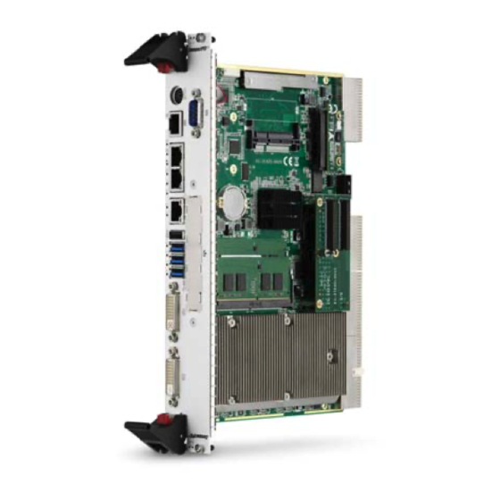
Introduction 1.1 Overview The ADLINK cPCI-6630 Series is a 6U 4/8 HP CompactPCI® pro- cessor blade featuring a 6th generation Intel® Core™ i7/i3/Cel- eron® processor and Mobile Intel® HM170 PCH with DDR4-2133 non ECC memory up to 32GB via 2 SODIMM sockets. The sin- gle-slot 4HP cPCI-6630 features front panel I/O including 1x DVI-I, 1x DVI-D, 3x GbE, 3x USB 3.0, 1x USB 2.0, 1x RJ-45 COM port... -
Page 14: Features
Leading EDGE COMPUTING 1.2 Features 6U CompactPCI blade in 4/8HP width form factor Powered by single 5V power rail 14nm Intel® Core™ i7-6820EQ Processor (4 cores, 8 threads, 8MB Smart Cache, 2.8 GHz) and Mobile Intel® HM170 Chipset Graphics and memory controllers integrated in processor Supports H.265 hardware-accelerated HEVC 8-bit decoding and encoding Dual channel DDR4-2133 non-ECC via 2x DDR4-2133... -
Page 15: Package Contents
Please obtain authorization before returning any product to ADLINK. The packing contents of cPCI-6630 Series non-standard configurations will vary depending on customer requests. cPCI-6630 Processor Blade... - Page 16 Leading EDGE COMPUTING The contents of non-standard cPCI-6630 configurations may vary depending on the customer’s requirements. NOTE: NOTE: This product must be protected from static discharge and phys- ical shock. Never remove any of the components except at a static-free workstation. Use the anti-static bag shipped with the CAUTION: product when putting the board on a surface.
-
Page 17: Specifications
cPCI-6630 Specifications 2.1 cPCI-6630(D) Processor Blade Specifications CompactPCI® • PICMG® 2.0 CompactPCI® Rev. 3.0 Standards • PICMG® 2.1 Hot Swap Specification Rev. 2.0 • PICMG® 2.16 Packet Switching Backplane Rev. 1.0 Mechanical • Standard 6U CompactPCI® • Board size: 233mm x 160mm •... - Page 18 Leading EDGE COMPUTING Serial Ports • Up to four serial ports • Up to two RS-232/422/485 serial ports on front panel (one on cPCI-6630, two on cPCI-6630D) • Two RS-232 COM port routed to J3 USB 2.0 • One USB 2.0 port on front panel •...
- Page 19 cPCI-6630 Environmental • Operating Temperature (with forced air flow) Standard: -20°C to +60°C Extended: -20°C to +70°C with forced air flow • Storage Temperature: -50°C to 100°C • Humidity: 95% @60°C non-condensing • Shock: 20G peak-to-peak, 11ms duration, non-operating • Vibration : 2Grms, 5-500Hz, each axis, operating (w/o hard drive) •...
-
Page 20: Block Diagrams
Leading EDGE COMPUTING 2.2 Block Diagrams cPCI-6630(D) Blade Front Panel (2 layer) Front Panel USB 2.0 DP to Intel Intel Intel USB 2.0 SO-DIMM, max. 16GB I210 COM1 I219 I210 USB 3.0 Controller SO-DIMM, max. 16GB BIOS PCIe x1 COM2 PCIe x1 DDPB/C PCIe x1... -
Page 21: I/O Connectivity Table
cPCI-6630 2.3 I/O Connectivity Table cPCI-6630 (4HP) cPCI-6630D (8HP) Function Faceplate Onboard Faceplate Onboard Gigabit Ethernet Y x3 – Y x3 – Y x2 (RJ-45 & Y x1 (RJ-45) – – DB-9) USB 3.0 Y x3 – Y x3 – USB 2.0 Y x1 –... -
Page 22: Power Requirements
Leading EDGE COMPUTING 2.4 Power Requirements In order to guarantee a stable functionality of the system, it is rec- ommended to provide more power than the system requires. An industrial power supply unit should be able to provide at least twice as much power as the entire system requires of each voltage. - Page 23 cPCI-6630 Power Consumption This section provides information on the power consumption of the cPCI-6630(D) when using Intel® Core™ i7/Celeron® processors with 4GB DDR4-2133 SODIMM memory. Storage device is used with ADLINK ASD26-MLC64G-CT 64GB SATA SSD. The cPCI-6630 is powered by 5V only. Power consumption at 100% CPU usage was measured by running Intel Thermal Analysis Tool 5.0.1026 (TAT).
- Page 24 Leading EDGE COMPUTING This page intentionally left blank. Specifications...
-
Page 25: Functional Description
The processor includes an Integrated Display Engine, Processor Graphics and Integrated Memory Controller. The cPCI-6630 Series supports Intel® Core™ i7/i5 processors. The table below lists the general specifications and power ratings of the CPUs supported by the cPCI-6630 Series. - Page 26 Leading EDGE COMPUTING Supported Technologies Feature Core™ i7-6820EQ Core™ i3-6100E Celeron® G3900E Intel® Turbo Boost Technology Intel® vPro Technology Intel® Hyper-Threading Technology Intel® Virtualization Technology (Intel® VT-x) Intel® Virtualization Technology for Directed I/O (Intel® VT-d) Intel® VT-x with Extended Page Tables (EPT) Intel®...
-
Page 27: Chipset
cPCI-6630 Graphics The Intel® HD Graphics 530 for Core™ i7 and Core™ i3 and Intel® HD Graphics 510 for Celeron® is integrated in the proces- sor enabling substantial gains in performance and lower power consumption. DX12 support OpenGL 4.4, OpenCL 1.2 support Graphics Base Frequency: 3500 MHz Graphics Max Dynamic Frequency: 1 GHz for Core™... -
Page 28: Pmc
Leading EDGE COMPUTING 3.3 PMC The cPCI-6630D supports one 32-bit/33MHz PMC site for front panel I/O expansion. The PMC site provides a maximum 32-bit/33 MHz PCI bus link using a TI XIO2001 PCI-Express-to-PCI bridge via PCI-Express x4 link. The PMC site supports +3.3V signaling only. -
Page 29: Battery
cPCI-6630 3.6 Battery The cPCI-6630(D) is equipped with a 3.0V "coin cell" lithium bat- tery for the real time clock (RTC). The lithium battery must be replaced with an identical battery or a battery type recommended by the manufacturer. A Rayovac BR2032 is equipped on board by default. - Page 30 Leading EDGE COMPUTING This page intentionally left blank. Functional Description...
-
Page 31: Board Interfaces
Board Interfaces This chapter illustrates the board layout, connector pin assignments, and jumper settings to familiarize users with the cPCI-6630 Series. 4.1 cPCI-6630(D) Component Side Layout CN15 CN6/CN7 CN13 SW_COMPW2 CN12 SATA1 BAT1 CN11 CN10 CN_VIO GDCN1 GCCN1 ®... -
Page 32: Cpci-6630 Solder Side Layout
Leading EDGE COMPUTING 4.2 cPCI-6630 Solder Side Layout SW12 SW13 SWCOMDEG2 SW10 SW14 SW11 SW_COMDEG2 Reserved SW10 LAN (CN12) front/rear switch Reset button SW11 “Force ejector handle closed” switch COM2 mode switch SW12 PS/2 front/rear switch Clear CMOS SW13 DVI-D digital signal front/rear switch COM1 mode switch SW14... -
Page 33: Cpci-6630D Assembly Layoutt
cPCI-6630 4.3 cPCI-6630D Assembly Layoutt DB-6965PMC CPU heatsink DB-6965PMC 32Bit/33MHz PMC adapter Figure 4-3: cPCI-6630D Assembly Layout Board Interfaces... -
Page 34: Cpci-6630(D) Front Panel
Leading EDGE COMPUTING 4.4 cPCI-6630(D) Front Panel cPCI-6630 PS/2 Serial Port GbE x3 USB 3.0 x3 DVI-I DVI-D COM1 KB/MS USB 2.0 Reset Power LED User LEDs Button General Purpose LED HDD LED WDT LED cPCI-6630D Serial Port COM2 Serial Port GbE x3 USB 2.0 USB 3.0 x3... -
Page 35: Table 4-1: Cpci-6630(D) Front Panel System Led Descriptions
cPCI-6630 System LEDs Color Condition Indication System is off Power Green/ System Power ready (PWGD) Green Post OK No Watchdog event Orange Blinking Watchdog event alert No CF/CFast/SATA HDD activity Yellow Data read/write in process for CF/CFast/ Blinking SATA HDD General Off by default (user programmable, Fast Blink... -
Page 36: User Leds
Leading EDGE COMPUTING 4.5 User LEDs During bootup, the eight User LEDs on the faceplate display port 80h POST codes in hexadecimal during boot up. Users can use the POST codes to identify issues during the BIOS POST process. In default mode, these eight LEDs display the POST code output to Port 80h during system bootup. -
Page 37: Connector Pin Assignments
cPCI-6630 4.6 Connector Pin Assignments DVI-I Connector (GDCN1) Pin # Signal Pin # Signal TMDS Data2- Hot Plug Detect TMDS Data2+ TMDS Data0- TMDSData0+ DDC Clock [SCL] DDC Data [SDA] Analog vertical sync TMDS Clock + TMDS Data1- TMDS Clock - TMDS Data1+ Analog Red Analog Green... -
Page 38: Table 4-3: Dvi-D Connector Pin Definition
Leading EDGE COMPUTING DVI-D Connector (GCCN1) Pin # Signal Pin # Signal TMDS Data2- Hot Plug Detect TMDS Data2+ TMDS Data0- TMDSData0+ DDC Clock [SCL] DDC Data [SDA] Analog vertical sync TMDS Clock + TMDS Data1- TMDS Clock - TMDS Data1+ +5 V Power Table 4-3: DVI-D Connector Pin Definition Board Interfaces... -
Page 39: Table 4-4: Usb 2.0 Pin Definition
cPCI-6630 USB 2.0 Connectors Pin # Signal Name UV0- UV0+ Table 4-4: USB 2.0 Pin Definition USB 3.0 Connectors Pin # Signal Name Data- Data+ RX_N RX_P TX_N TX_P Board Interfaces... -
Page 40: Table 4-5: Front Panel Com1 Pin Definitions
Leading EDGE COMPUTING COM1 (RJ-45) Pin # RS-232 RS-422 RS-485 DCD# Data- RTS# — — DSR# — — — Data+ — — CTS# — — DTR#L — Table 4-5: Front Panel COM1 Pin Definitions COM2, COM RJ-45 to DB-9 Cable Pin # RS-232 RS-422... -
Page 41: Table 4-7: Rj-45 Gbe Pin Definitions
cPCI-6630 RJ-45 Gigabit Ethernet Connectors 10BASE-T/ Pin # 1000BASE-T 100BASE-TX LAN_TX0+ LAN_TX0- LAN_TX1+ — LAN_TX2+ — LAN_TX2- LAN_TX1- — LAN_TX3+ — LAN_TX3- Table 4-7: RJ-45 GbE Pin Definitions Speed Activity Speed LED Activity LED Status (Green/Amber) (Yellow) Network link is not established or system powered off Link 10 Mbps... -
Page 42: Table 4-9: Serial Ata 7-Pin Connector Pin Definition
Leading EDGE COMPUTING Serial ATA 7-pin Connector (SATA1) Pin # Signal Table 4-9: Serial ATA 7-pin Connector Pin Definition Serial ATA Connector with Power Pin # Signal Signal Power P13~P15 Table 4-10: Serial ATA Connector with power Pin Definition Board Interfaces... -
Page 43: Table 4-11: Cfast Socket Pin Definition
cPCI-6630 CFast Socket Pin # Signal Name Ground SATA_TX-P SATA_TX-N Ground SATA_RX-N SATA_RX-P Ground CFast_CDI Ground Ground CFast_LED1 CFast_LED2 +3.3V +3.3V Ground Ground CFast_CDO Table 4-11: CFast Socket Pin Definition Board Interfaces... -
Page 44: Table 4-12: Pmc Connector Pin Definitions
Leading EDGE COMPUTING PMC Connectors (JN1, JN2) Pin# JN1 Signal JN2 Signal PMC_TCK P12V N12V* PMC_TRST-L PMC_TMS PCIX_INTA-L NC (PMC_TDO) PCIX_INTB-L PMC_TDI PCIX_INTC-L PMC_MOD-L1 PCIX_INTD-L PMC_MOD-L2 P3V3_PMCAUX P3V3 PCI_PCLK0 PMC_RST-L PMC_MOD-L3 P3V3 PCIX_GNT-L0 PMC_MOD-L4 PCIX_REQ-L0 PMC_PME-L PMC_VIO PCIX_AD30 PCIX_AD31 PCIX_AD29 PCIX_AD28 PCIX_AD27 PCIX_AD26... - Page 45 cPCI-6630 Pin# JN1 Signal JN2 Signal PCIX_FRAME-L PCIX_TRDY-L PCIX_IRDY-L P3V3 PCIX_DEVSEL-L PCIX_STOP-L PMC_PCIXCAP PCIX_PERR-L PCIX_LOCK-L P3V3 PCIX_SERR-L PCIX_PAR PCIX_CBE-L1 PMC_VIO PCIX_AD14 PCIX_AD15 PCIX_AD13 PCIX_AD12 PCIX_M66EN PCIX_AD11 PCIX_AD10 PCIX_AD9 PCIX_AD8 P3V3 PCIX_AD7 PCIX_CBE-L0 PCIX_AD6 P3V3 PCIX_AD5 PCIX_AD4 PMC_VIO PCIX_AD3 PCIX_AD2 PCIX_AD1 PCIX_AD0 PCIX_ACK64-L P3V3...
-
Page 46: Table 4-13: Compactpci J1 Connector Pin Definition
Leading EDGE COMPUTING CompactPCI J1 Connector CPCI_REQ64-L CPCI_ENUM-L +3.3V CPCI_AD1 CPCI_VIO CPCI_AD0 CPCI_ACK64-L GND +3.3V CPCI_AD4 CPCI_AD3 CPCI_AD2 CPCI_AD7 +3.3V CPCI_AD6 CPCI_AD5 +3.3V CPCI_AD9 CPCI_AD8 CPCI_M66EN CPCI_CBE-L0 GND CPCI_AD12 CPCI_VIO_STB CPCI_AD11 CPCI_AD10 +3.3V CPCI_AD15 CPCI_AD14 CPCI_AD13 CPCI_SERR-L +3.3V CPCI_PAR CPCI_CBE-L1 GND +3.3V IPMCB_CLK IPMB_DAT... -
Page 47: Table 4-14: Compactpci J2 Connector Pin Definition
cPCI-6630 CompactPCI J2 Connector CPCI_CLK6 CPCI_CLK5 IPMB_DAT IPMB_CLK IPMB_PWR J2_RST-L CPCI_REQ-L6 CPCI_GNT-L6 GND CPCI_DEG-L CPCI_FAL-L CPCI_REQ-L5 CPCI_GNT-L5 GND CPCI_AD35 CPCI_AD34 CPCI_AD33 CPCI_AD32 CPCI_AD38 CPCI_VIO CPCI_AD37 CPCI_AD36 CPCI_AD42 CPCI_AD41 CPCI_AD40 CPCI_AD39 CPCI_AD45 CPCI_VIO CPCI_AD44 CPCI_AD43 CPCI_AD49 CPCI_AD48 CPCI_AD47 CPCI_AD46 CPCI_AD52 CPCI_VIO CPCI_AD51 CPCI_AD50 CPCI_AD56... -
Page 48: Table 4-15: Compactpci J3 Connector Pin Definition
Leading EDGE COMPUTING CompactPCI J3 Connector Pin Z P12V 19 GND 18 GND LAN3_MDI0_P LAN3_MDI0_N LAN3_MDI2_P LAN3_MDI2_N 17 GND LAN3_MDI1_P LAN3_MDI1_N LAN3_MDI3_P LAN3_MDI3_N 16 GND LAN2_MDI0_P LAN2_MDI0_N LAN2_MDI2_P LAN2_MDI2_N 15 GND LAN2_MDI1_P LAN2_MDI1_N LAN2_MDI3_P LAN2_MDI3_N 14 GND USB_OC3-L USB_OC4-L USB_OC5-L USB_OC6-L USB_OC7-L 13 GND... -
Page 49: Table 4-16: Compactpci J5 Connector Pin Definition
cPCI-6630 CompactPCI J5 Connector LAN2_LED_ LAN3_LED_ PWELED-L 22 GND ACT-L ACT-L 21 GND 20 GND 19 GND DETECT-L 18 GND REAR_GPIO8 17 GND REAR_GPIO7 16 GND REAR_GPIO6 SATA_RX3_P_C SATA_RX3_N_C 15 GND SATA-TX3_P_C SATA-TX3_N_C 14 GND LAN2_LED_ LAN3_LED_ LAN3_LED_ LAN2_LED_ 13 GND 100-L 100-L 1000-L... -
Page 50: Switches And Buttons
Leading EDGE COMPUTING 4.7 Switches and Buttons Refer to Section 4.1 cPCI-6630(D) Component Side Layout on page 19 and Section 4.2 cPCI-6630 Solder Side Layout on page 20 for switch and button locations. System Reset Button (SW1) The cPCI-6630(D) has a system reset button on the front panel. Press the switch SW1 to reset the system. - Page 51 cPCI-6630 DVI-I VGA Signal Front/Rear Switch (SW8) Switch SW8 routes the VGA signals of the DVI-I port to either the front panel or rear I/O. Rear I/O Front Panel (default) Reserved Reserved (default) GbE (CN12) Front/Rear Switch (SW10) Switch SW10 routes the GbE (CN12) signals to either the front panel or rear I/O.
- Page 52 Leading EDGE COMPUTING Force Ejector Handle Closed Switch (SW11) Switch SW11 allows the ejector handle state to be forced "closed" so that blades without ejector handles (e.g. conduction cooled) will power on when inserted into the chassis. Force the ejector handle On/Off state is controlled state to "closed"...
- Page 53 cPCI-6630 DVI-D Digital Signal Front/Rear Switch (SW13) Switch SW13 routes the DVI-D signal to either the front panel or rear I/O. DVI-D to rear DVI-D to front (default) Reserved Reserved Debug Switch (SW14, Reserved) The default setting for SW14 is 1 OFF, 2 OFF. Do not change the settings unless instructed by ADLINK.
- Page 54 Leading EDGE COMPUTING COM Debug Switches (SW_COMDEG2, SW_COMPW2) Switch SW_COMDEG2 is set 1, 2 ON and 3, 4 OFF by default to set the front panel RJ-45 COM1 (RJ2) serial port as a standard RS-232 serial port. The setting can be changed to use RJ2 as an BMC debug port.
- Page 55 cPCI-6630 PMC VIO Function Jumper (CN_VIO) Jumper CN_VIO is located on the component side of the board. CN_VIO sets the PMC VIO to either 3.3V or 5V. Function Short 1-2 3V3 (default) Short 2-3 Board Interfaces...
- Page 56 Leading EDGE COMPUTING This page intentionally left blank. Board Interfaces...
-
Page 57: Getting Started
CFast card CompactFlash card 2.5” SATA drive PMC module installation 5.1 CPU and Heatsink The cPCI-6630 Series come with CPU and heatsink pre-installed. Removal of heatsink/CPU by users is not recommended. Please contact your ADLINK service representative for assistance. Getting Started... -
Page 58: Cfast Card Installation
Leading EDGE COMPUTING 5.2 CFast Card Installation The cPCI-6630(D) provides space to install a CFast card or a Com- pactFlash card (optional). Follow the instructions below to install a CFast to the cPCI-6630(D). 1. A CFast card can be installed in the location marked below. - Page 59 cPCI-6630 3. Insert the CFast card into the socket. Locate the strip of black foam in the CFast accessory pack and remove the backing from the adhesive side. Getting Started...
- Page 60 Leading EDGE COMPUTING 4. Attach the foam to the bracket as shown below. 5. Place the bracket on the board as shown below. Secure the bracket to the board by fastening the 2 screws removed in Step 2 on the solder side of the cPCI-6630(D).
-
Page 61: Compactflash Card Installation (Optional)
cPCI-6630 5.3 CompactFlash Card Installation (optional) Follow the instructions below to install a CompactFlash card to the cPCI-6630(D) with optional CF card slot. 1. A CompactFlash card can be installed in the location marked below. A retention bracket is pre-installed to secure the CompactFlash card in place. - Page 62 Leading EDGE COMPUTING 2. Turn the cPCI-6630(D) over and remove the two screws indicated below. Remove the retention bracket. Getting Started...
- Page 63 cPCI-6630 3. Insert the CompactFlash card into the CompactFlash slot. Secure the bracket on to the board by fastening the 2 screws removed in Step 2 on the solder side of cPCI-6630(D). Getting Started...
-
Page 64: Sata Drive Installation
Leading EDGE COMPUTING 5.4 2.5" SATA Drive Installation The cPCI-6630(D) provides space to install a 2.5” SATA drive. 1. A 2.5” SATA drive can be installed on the cPCI-6630(D) in the location shown below. The items in the 2.5” SATA drive accessory pack are shown on the right. - Page 65 cPCI-6630 3. Secure the 2.5” SATA drive to the drive bracket by fas- tening 4 screws (M3 L4, flat head) on both sides of the bracket as indicated below. 4. Place the SATA drive and drive bracket assembly onto cPCI-6630(D) by fastening two screws(M2.5 L6, round head) circled as below.
- Page 66 Leading EDGE COMPUTING 5. Turn the board over and finish securing the SATA drive and drive bracket assembly by fastening two screws (M2.5 L6, round head) )as shown below. Getting Started...
-
Page 67: Pmc Installation (Cpci-6630D Only)
cPCI-6630 5.5 PMC Installation (cPCI-6630D only) The cPCI-6630D provides space to install one PMC module. Fol- low following steps to install a PMC module. 1. A PMC module can be installed on the cPCI-6630D in the location indicated below. Locate the two male/female standoffs (M2.5, H15) and two screws (M2.5 L6, round head) in the PMC accessory pack. - Page 68 Leading EDGE COMPUTING 2. Remove the PMC filler plate and the screws securing two brackets to the front panel as shown below. 3. Locate the DB-6965PMC daughter board in the PMC accessory pack and attach it to the JN1/JN2 PMC board-to-board connectors on the cPCI-6630D in the location shown below.
- Page 69 cPCI-6630 4. Secure the two brackets removed in Step 2 above to the PMC card as shown below. Getting Started...
- Page 70 Leading EDGE COMPUTING 5. Locate the two female/female standoffs provided in the PMC accessory pack and fasten them to secure the DB-6965PMC daughter board as shown. 6. Align the connectors of the PMC card with those on the DB-6965PMC daughter board and fasten with two screws as indicated below.
- Page 71 cPCI-6630 7. Fasten the two screws removed in Step 2 above to the front panel to complete securing the PMC card to the cPCI-6630D. Set aside the PMC filler plate so it can be replaced if the PMC card is uninstalled. Getting Started...
-
Page 72: Installing The Cpci-6630(D) To The Chassis
Leading EDGE COMPUTING 5.6 Installing the cPCI-6630(D) to the Chassis The cPCI-6630(D) may be installed in a system or peripheral slot of a 6U CompactPCI chassis. These instructions are for reference only. Refer to the user guide that comes with the chassis for more information. -
Page 73: Driver Installation
cPCI-6630 Driver Installation The cPCI-6630 drivers can be downloaded from the ADLINK web- site ( http://www.adlinktech.com ). ADLINK provides validated drivers for Windows 7 and Windows 10. We recommend using these drivers to ensure compatibility. VxWorks BSP and QNX BSP can also be downloaded from the cPCI-6630 product page on the ADLINK website. - Page 74 Leading EDGE COMPUTING This page intentionally left blank. Driver Installation...
-
Page 75: Utilities
cPCI-6630 Utilities 7.1 Watchdog Timer This section describes the operation of the cPCI-6630’s watch dog timer (WDT). The primary function of the WDT is to monitor the cPCI-6630 operation and to reset the system if a software applica- tion fails to function as programmed. The following WDT functions may be controlled using a software application: enabling and disabling reloading timeout value... - Page 76 Leading EDGE COMPUTING Sample Code #include <stdio.h> #include <stdlib.h> typedefunsigned charBYTE; void EnterConfig() outportb(SIO_CONFIG_INDEX, 0x87); outportb(SIO_CONFIG_INDEX, 0x01); outportb(SIO_CONFIG_INDEX, 0x55); outportb(SIO_CONFIG_INDEX, 0x55); void ExitConfig() outportb(SIO_CONFIG_INDEX, 0x02); outportb(SIO_CONFIG_DATA, 0x02); void LDNSelection(BYTE LDN) outportb(SIO_CONFIG_INDEX, 0x07); outportb(SIO_CONFIG_DATA, LDN); void SIOBasicIORead( BYTE LDN, BYTE Register, BYTE *Data) LDNSelection(LDN);...
- Page 77 cPCI-6630 LDNSelection(LDN); outportb(SIO_CONFIG_INDEX, Register); outportb(SIO_CONFIG_DATA, Data); BOOL StringToByte(char *string, BYTE *value) BYTE i, temp; *value = 0; for(i=0; string[i]!=NULL; ++i) { if(i>1) { printf("Digital count error!\n"); return 0; } *value <<= 4; temp = toupper(string[i]); if(temp >='0' && temp <='9') *value += temp - '0';...
- Page 78 Leading EDGE COMPUTING printf("Input char[%c] is illegal!\n", string[i]); return 0; if(temp > 65535) { printf("Input number is large than 65535!\n"); return1; int IT8786_WatchDog(int argc, char *argv[]) BYTE bTemp, bUnit; WORD wWdtimer; printf("ADLINK WatchDog DOS Utility [Version 1.00]\n\n"); if((argc != 3) && strcmp(argv[1], "/?")) { printf("Invalid command, please type /? to get the details.\n");...
- Page 79 cPCI-6630 printf("Argument1 is a invalid number[%d].\n", bUnit); return 1; StringToWORD_Dec(argv[2], &wWdtimer); EnterConfig(); // Implement Watch Dog SIOBasicIORead(0x07, 0x29, &bTemp); bTemp &= ~BIT6; // default function = KRST SIOBasicIOWrite(0x07, 0x29, bTemp); // Config settings if(bUnit) { bTemp = 0xd0; // second } else { bTemp = 0x50;...
-
Page 80: User Led Programming
Leading EDGE COMPUTING 7.2 User LED Programming The eight User LEDs on the front panel display port 80h POST codes in hexadecimal during boot up. Users can use the POST codes to identify issues during the BIOS POST process. In default mode, these eight LEDs display the POST code output to Port 80h during system bootup (see “User LEDs”... - Page 81 cPCI-6630 if(i<7) bData2 = bData2 << 1; outportb(IT8786_GPIO_BASE_ADDRESS+0x06, bData); Utilities...
- Page 82 Leading EDGE COMPUTING This page intentionally left blank. Utilities...
-
Page 83: Bios Setup Utility
cPCI-6630 BIOS Setup Utility The following chapter describes basic navigation for the AMI EFI BIOS setup utility. 8.1 Starting the BIOS To enter the setup screen, follow these steps: 1. Power on the motherboard 2. Press the < Delete > key on your keyboard when you see the following text prompt: <... - Page 84 Leading EDGE COMPUTING Setup Menu The main BIOS setup menu is the first screen that you can navi- gate. Each main BIOS setup menu option is described in this user’s guide. The Main BIOS setup menu screen has two main frames. The left frame displays all the options that can be configured.
- Page 85 cPCI-6630 Navigation Note: There is a hot key legend located in the right frame on most setup screens. Keyboard Commands The Left and Right "Arrow" keys allow you to select a setup < > screen. The Up and Down "Arrow" keys allow you to select a setup screen.
- Page 86 Leading EDGE COMPUTING Hotkey Descriptions Enter The < Enter > key allows you to display or change the setup option listed for a particular setup item. The < Enter > key can also allow you to display the setup sub-screens. The <...
- Page 87 cPCI-6630 conflicting settings. The < F4 > key allows you to save any changes you have made and exit Setup. Press the < F10 > key to save your changes. The following screen will appear: Press the < Enter > key to save the configuration and exit. You can also use the <...
-
Page 88: Main Setup
Leading EDGE COMPUTING 8.2 Main Setup When you first enter the Setup Utility, you will enter the Main setup screen which reports BIOS, processor, and PCH information. BIOS Setup Utility... -
Page 89: System Management
cPCI-6630 8.2.1 System Management Select the Main tab from the setup screen to enter the System Management Setup screen. You can select any of the items in the left frame of the screen to go to the sub menu for that item. The System Management BIOS Setup screen is shown below. - Page 90 Leading EDGE COMPUTING Board Information You can use this screen to view Board related information. An example of the Board screen is shown below. Temperatures and Fan Speed BIOS Setup Utility...
- Page 91 cPCI-6630 Power Consumption Information Runtime Statistics Information Flags BIOS Setup Utility...
- Page 92 Leading EDGE COMPUTING System Date/System Time Use this option to change the system date and time. Highlight Sys- tem Time or System Date using the < Arrow > keys. Enter new val- ues using the keyboard. Press the < Tab > key or the < Arrow > keys to move between fields.
-
Page 93: Advanced Bios Setup
cPCI-6630 8.3 Advanced BIOS Setup Select the Advanced tab from the setup screen to enter the Advanced BIOS Setup screen. You can select any of the items in the left frame of the screen to go to the sub menu for that item. You can display an Advanced BIOS Setup option by highlighting it using the <... -
Page 94: Amt Configuration
Leading EDGE COMPUTING 8.3.1 AMT Configuration You can use this screen to select options for the AMT settings. Use the up and down < Arrow > keys to select an item. Use the < + > and < - > keys to change the value of the selected option. Intel AMT Intel AMT feature. -
Page 95: Pch-Fw Configuration
cPCI-6630 8.3.2 PCH-FW Configuration You can use this screen to view ME related information. For exam- ple, ME FW Version, ME Firmware Mode, ME Firmware Type, ME Firmware SKU..etc. An example of the ME screen is shown below. BIOS Setup Utility... -
Page 96: It8786 Super Io Configuration
Leading EDGE COMPUTING 8.3.3 IT8786 Super IO Configuration You can use this screen to select options for the IT8786 Super IO settings. Use the up and down < Arrow > keys to select an item. Use the < + > and < - > keys to change the value of the selected option. - Page 97 cPCI-6630 Serial Port 1,2,3,4 Configuration Set Parameters of Serial Port 1/ 2/ 3/ 4 (COM 1/ 2/ 3/ 4). Serial Port Set this Serial Port to Enabled/Disabled. Change Settings Select an optimal setting for Super IO Device. The options are “Auto, 3F8h, 2F8h…”etc.
-
Page 98: Hardware Monitor
Leading EDGE COMPUTING 8.3.4 Hardware Monitor This option displays the current status of all of the monitored hard- ware devices/components such as voltages and temperatures. BIOS Setup Utility... -
Page 99: Serial Port Console Redirection
cPCI-6630 8.3.5 Serial Port Console Redirection You can use this screen to select options for the serial port con- sole redirection settings. An example of the Serial Port Console Redirection screen is shown below. Console Redirection Set this value to Enabled/Disabled. Console Redirection Settings The settings specify how the host computer and the remote com- puter will exchange data. - Page 100 Leading EDGE COMPUTING Terminal Type VT100+ is the preferred terminal type for out-of-band manage- ment. Configuration options: VT100, VT100+, VT-UTF8, ANSI. Bits per second Select the bits per second you want the serial port to use for console redirection. The options are 115200, 57600, 38400, 19200, 9600.
- Page 101 cPCI-6630 Stop Bits Stop bits indicate the end of a serial data packet. (A start bit indicates the beginning). The standard setting is 1 stop bit. Communication with slow devices may require more than 1 stop bit. Set this value to 1 and 2. Flow Control Set this option to select Flow Control for console redirection.
- Page 102 Leading EDGE COMPUTING Legacy Console Redirection Legacy Console Redirection Settings. Select a COM port to dis- play redirection of Legacy OS and Legacy OPROM Messages. Serial Port for Out-of-Band Management / Windows Emer- gency Management Services (EMS) Out-of-Band Mgmt Port Microsoft Windows Emergency Management Services (EMS) allows for remote management of a Windows Server OS through a serial port.
- Page 103 cPCI-6630 Bits per Second Selects serial port transmission speed. The speed must be matched on the other side. Long or noisy lines may require lower speeds. Flow Control Set this option to select Flow Control for console redirection. The settings for this value are None, Hardware RTS/CTS, Soft- ware Xon/Xoff.
-
Page 104: Cpu Configuration
Leading EDGE COMPUTING 8.3.6 CPU Configuration You can use this screen to select options for the CPU Configura- tion Settings. The settings are described on the following pages. An example of the CPU Configuration screen is shown below. BIOS Setup Utility... - Page 105 cPCI-6630 Hyper-Threading Enabled: for Windows and Linux (OS optimized for Hyper-Threading Technology). Disabled: for other OS (OS not optimized for Hyper-Threading Technology). Active Processor Cores Number of cores to enable in each processor package. Intel Virtualization Technology When Enabled, a VMM can utilize the additional hardware capabil- ity provided by Vanderpool Technology.
-
Page 106: Sata Configuration
Leading EDGE COMPUTING 8.3.7 SATA Configuration You can use this screen to select options for the SATA Configura- tion Settings. An example of the SATA Configuration screen is shown below. SATA Controller(s) Enable or disable SATA device. SATA Mode Selection The SATA can be configured as a legacy IDE, RAID and AHCI mode. - Page 107 cPCI-6630 Software Feature Mask Configuration RAID OROM/RST driver will refer to the SWFM configuration to enable or disable the storage features. RAID0/1/10/5 Enable or disable RAID0/1/10/5 feature. Intel Rapid Recovery Technology Enable or disable Intel Rapid Recovery Technology. OROM UI and Banner If enabled, the OROM UI is shown.
- Page 108 Leading EDGE COMPUTING IRRT Only on eSATA If enabled, then only IRRT volumes can span internal and eSATA drives. If disabled, then any RAID volume can span internal and eSATA drives. Smart Response Technology Enable or disable Smart Response Technology. OROM UI Delay If enabled, indicates the delay of the OROM UI Splash Screen under normal status.
-
Page 109: Network Stack Configuration
cPCI-6630 8.3.8 Network Stack Configuration Network Stack Enable/Disable UEFI Network Stack. IPv4 PXE Support Enable IPv4 PXE Boot Support. If disabled, the IPv4 PXE boot option will not be created. IPv6 PXE Support Enable IPv6 PXE Boot Support. If disabled, the IPv6 PXE boot option will not be created. -
Page 110: Csm Configuration
Leading EDGE COMPUTING 8.3.9 CSM Configuration CSM Support Enable/Disable CSM Support. GateA20 Active Upon Request: GA20 can be disabled using BIOS services. Always: do not allow disabling of GA20; this option is useful when any RT code is executed above 1MB. Option ROM Messages Set the display mode for Option ROM. - Page 111 cPCI-6630 Boot Option Filter This option controls Legacy/UEFI ROM priority. Set this value to UEFI and Legacy, Legacy only, UEFI only. Network Controls the execution of UEFI and Legacy PXE OpROM. Set this value to Do not launch, Legacy, UEFI. Storage Controls the execution of UEFI and Legacy PXE OpROM.
-
Page 112: 10Usb Configuration
Leading EDGE COMPUTING 8.3.10 USB Configuration You can use this screen to select options for the USB Configura- tion. Use the up and down < Arrow > keys to select an item. The screen is shown below. Legacy USB Support Enables legacy USB support. - Page 113 cPCI-6630 USB Mass Storage Driver Support Enable/Disable USB Mass Storage Driver Support. Mass Storage Devices: Mass storage device emulation type. 'AUTO' enumerates devices according to their media format. Optical drives are emulated as 'CDROM', drives with no media will be emulated according to a drive type.
-
Page 114: Chipset Setup
Leading EDGE COMPUTING 8.4 Chipset Setup Select the Chipset tab from the setup screen to enter the Chipset BIOS Setup screen. You can select any of Chipset BIOS Setup options by highlighting it using the < Arrow > keys. The Chipset BIOS Setup screen is shown below. -
Page 115: System Agent (Sa) Configuration
cPCI-6630 8.4.1 System Agent (SA) Configuration VT-d The Intel Virtualization Technology for Directed I/O. Set this value to Enabled/Disabled. BIOS Setup Utility... - Page 116 Leading EDGE COMPUTING Graphics Configuration VGA Channel Switch Sets the VGA signal output to Front or Rear IO. Primary Display Select which graphics device should be the primary display. Set this value to Auto, IGFX, PCI. Internal Graphics Keep IGD enabled based on the setup options. Set this value to Auto, Enabled, Disabled.
- Page 117 cPCI-6630 Primary IGFX Boot Display Select Boot Video Device during POST VBIOS Default: auto-detect video device by vBIOS. Front DVI-D, Rear DVI-D, Front DVI-I, VGA: force to boot with selected video device. Memory Configuration BIOS Setup Utility...
- Page 118 Leading EDGE COMPUTING PEG Port Configuration Configure the PCI Express port from the CPU. Enable Root Port Enable or disable the PEG port. Max Link Speed Configure PEG Bus:0 Dev:1 Fun:1. Max. Speed options: Auto or Gen1. BIOS Setup Utility...
-
Page 119: Pch-Io Configuration
cPCI-6630 8.4.2 PCH-IO Configuration BIOS Setup Utility... - Page 120 Leading EDGE COMPUTING PCI Express Configuration Configure the PCI Express ports from the PCH. PCI Express Root Port 5, 12-14 Configure the PCI Express Root Ports 5, 12-14. PCI Express Root Port 5, 12-14 Enable/disable the PCI Express port. PCI Speed Select PCI Express port speed: Gen1, Gen2, Gen3 BIOS Setup Utility...
- Page 121 cPCI-6630 HD Audio Configuration HD Audio Enable/Disable the HD Audio device. Disabled: HDA will be unconditionally disabled Enabled: HDA will be unconditionally Enabled Auto: HDA will be enabled if present, disabled otherwise. PCH LAN Controller Enable/Disable the PCH LAN Controller. LAN #2 / #3 (Intel I210IT) Direct LAN 2/3 to either Front or Rear IO.
-
Page 122: Boot Settings
Leading EDGE COMPUTING 8.5 Boot Settings Select the Boot tab from the setup screen to enter the Boot BIOS Setup screen. You can select any of the items in the left frame of the screen, such as Boot Device Priority, to go to the sub menu for that item. - Page 123 cPCI-6630 Set Boot Priority Set Boot Option #1 ~2 boot priority. Hard Disk Drive BBS Priorities Specifies the Boot Device Priority sequence from available Hard Disk Drives. BIOS Setup Utility...
-
Page 124: Security Setup
Leading EDGE COMPUTING 8.6 Security Setup Administrator, User Password If only the administrator's password is set, then this only limits access to setup and is only asked for when entering setup. If only the user's password is set, then this is a power on password and must be entered to boot or enter setup. -
Page 125: Save & Exit Menu
cPCI-6630 8.7 Save & Exit Menu Select the Save & Exit tab from the setup screen to enter the Save & Exit BIOS Setup screen. You can display an Exit BIOS Setup option by highlighting it using the < Arrow > keys. The Save & Exit BIOS Setup screen is shown below. - Page 126 Leading EDGE COMPUTING Save Changes Save changes done so far to any of the setup options. Discard Changes Discard changes done so far to any of the setup options. Restore Defaults Restore/Load Defaults values for all the setup options. Save as User Defaults Save the changes done so far as user defaults..
-
Page 127: Checkpoints & Beep Codes
cPCI-6630 Checkpoints & Beep Codes The eight User LEDs on the front panel display port 80h POST codes in hexadecimal during boot up. Users can use the POST codes to identify issues during the BIOS POST process (see See “User LEDs” on page 24.). 9.1 Checkpoint Ranges Status Code Range Description... - Page 128 Leading EDGE COMPUTING Status Code Description 0x05 OEM initialization before microcode loading 0x06 Microcode loading 0x07 AP initialization after microcode loading North Bridge initialization after microcode 0x08 loading South Bridge initialization after microcode 0x09 loading 0x0A OEM initialization after microcode loading 0x0B Cache initialization SEC Error Codes...
- Page 129 cPCI-6630 Status Code Description Pre-Memory North Bridge initialization (North 0x18 Bridge module specific) 0x19 Pre-memory South Bridge initialization is started Pre-memory South Bridge initialization (South 0x1A Bridge module specific) Pre-memory South Bridge initialization (South 0x1B Bridge module specific) Pre-memory South Bridge initialization (South 0x1C Bridge module specific) 0x1D –...
- Page 130 Leading EDGE COMPUTING Status Code Description Post-Memory North Bridge initialization (North 0x3A Bridge module specific) Post-Memory South Bridge initialization is 0x3B started Post-Memory South Bridge initialization (South 0x3C Bridge module specific) Post-Memory South Bridge initialization (South 0x3D Bridge module specific) Post-Memory South Bridge initialization (South 0x3E Bridge module specific)
- Page 131 cPCI-6630 Status Code Description 0xE2 Video repost 0xE3 OS S3 wake vector call 0xE4-0xE7 Reserved for future AMI progress codes S3 Resume Error Codes 0xE8 S3 Resume Failed 0xE9 S3 Resume PPI not Found 0xEA S3 Resume Boot Script Error 0xEB S3 OS Wake Error 0xEC-0xEF...
- Page 132 Leading EDGE COMPUTING PEI Beep Codes # of Beeps Description Memory not Installed Memory was installed twice (InstallPeiMemory routine in PEI Core called twice) Recovery started DXEIPL was not found DXE Core Firmware Volume was not found Recovery failed S3 Resume failed Reset PPI is not available DXE Phase Status Code...
- Page 133 cPCI-6630 Status Code Description North Bridge DXE initialization (North Bridge 0x6F module specific) 0x70 South Bridge DXE initialization is started 0x71 South Bridge DXE SMM initialization is started 0x72 South Bridge devices initialization South Bridge DXE Initialization (South Bridge 0x73 module specific) South Bridge DXE Initialization (South Bridge 0x74...
- Page 134 Leading EDGE COMPUTING Status Code Description 0xA0 IDE initialization is started 0xA1 IDE Reset 0xA2 IDE Detect 0xA3 IDE Enable 0xA4 SCSI initialization is started 0xA5 SCSI Reset 0xA6 SCSI Detect 0xA7 SCSI Enable 0xA8 Setup Verifying Password 0xA9 Start of Setup Reserved for ASL (see ASL Status Codes 0xAA section below)
- Page 135 cPCI-6630 Status Code Description Some of the Architectural Protocols are not 0xD3 available 0xD4 PCI resource allocation error. Out of Resources 0xD5 No Space for Legacy Option ROM 0xD6 No Console Output Devices are found 0xD7 No Console Input Devices are found 0xD8 Invalid password Error loading Boot Option (LoadImage returned...
-
Page 136: Oem-Reserved Checkpoint Ranges
Leading EDGE COMPUTING ACPI/ASL Checkpoints Status Code Description 0x01 System is entering S1 sleep state 0x02 System is entering S2 sleep state 0x03 System is entering S3 sleep state 0x04 System is entering S4 sleep state 0x05 System is entering S5 sleep state 0x10 System is waking up from the S1 sleep state 0x20... -
Page 137: Important Safety Instructions
cPCI-6630 Important Safety Instructions For user safety, please read and follow all instructions , WARNINGS , CAUTIONS, and NOTES marked in this manual and on the associated equipment before handling/operating the equipment. Read these safety instructions carefully. Keep this user’s manual for future reference. Read the specifications section of this manual for detailed information on the operating environment of this equipment. - Page 138 Leading EDGE COMPUTING Never attempt to fix the equipment. Equipment should only be serviced by qualified personnel. A Lithium-type battery may be provided for uninterrupted, backup or emergency power. Risk of explosion if battery is replaced with one of an incorrect type.
-
Page 139: Getting Service
San Jose, CA 95138, USA Tel: +1-408-360-0200 Toll Free: +1-800-966-5200 (USA only) Fax: +1-408-360-0222 Email: info@adlinktech.com ADLINK Technology (China) Co., Ltd. 300 Fang Chun Rd., Zhangjiang Hi-Tech Park Pudong New Area, Shanghai, 201203 China Tel: +86-21-5132-8988 Fax: +86-21-5132-3588 Email: market@adlinktech.com...
Need help?
Do you have a question about the cPCI-6630 Series and is the answer not in the manual?
Questions and answers