
Related Manuals for ADLINK Technology NuIPC cPCI-6770 Series


Summary of Contents for ADLINK Technology NuIPC cPCI-6770 Series
- Page 1 NuIPC cPCI-6770 series 6U CompactPCI Low Power Pentium-III CPU Module with Advanced AGP Display User’s Guide Recycled Paper...
- Page 3 Trademarks NuIPC is a registered trademark of ADLINK Technology Inc. Other product names mentioned herein are used for identification purposes only and may be trademarks and/or registered trademarks of their respective...
- Page 4 Getting Service from ADLINK Customer Satisfaction is top priority for ADLINK TECHNOLOGY INC. If you need any help or service, please contact us. ADLINK TECHNOLOGY INC. Web Site http://www.adlinktech.com Sales & Service Service@adlinktech.com +886-2-82265877 +886-2-82265717 Address 9F, No. 166, Jian Yi Road, Chungho City, Taipei, 235 Taiwan Please email or FAX your detailed information for prompt, satisfactory, and consistent service.
-
Page 5: Table Of Contents
Table of Contents Tables ......................iii Figures......................iv Outline of Chapters ..................v Chapter 1 Introduction ................1 1.1 Product Description ................1 1.2 cPCI-6770 faceplate (2-slot) ..............2 1.3 Features 3 1.4 Functional Blocks and Main Board ............4 1.4.1 Functional Block Diagram............4 1.4.2 Main Board Drawing...............5 1.4.1 CompactPCI Bus Interface ............6 1.4.2... - Page 6 Chapter 3 Configuration................16 3.1 Switch and Jumper Pins ..............16 3.1.1 Switch Description ..............17 Chapter 4 Watchdog Timer ..............19 4.1 Watchdog Timer Overview..............19 4.2 Using the Watchdog in an Application ..........20 4.2.1 Watchdog Reset ..............20 Chapter 5 Driver Installation ..............21 5.1 VGA Driver Installation.................22 5.1.1 VGA Driver Installation for Windows 98/2000/NT ....22 5.2 LAN Driver Installation .................22...
- Page 7 List of Tables Table 1: Max. Power consumption for PIII-700 with 128MB RAM ..12 Table 2: Max. Power consumption for PIII-850 with 512MB RAM ..12 Table 3: Switch Cross-Reference Table..........16 Table 4: JP2 (Clear CMOS Content) ...........17 Table 5: JP1, JP3 and JP4 Settings ............17 Zero Ω...
- Page 8 List of figures Figure 1. cPCI-6770 faceplate ..............2 Figure 2. Functional Block Diagram............4 Figure 3. Main Board Drawing ..............5 Figure 4. BIOS Setup Screen ...............14 Figure 5. Watchdog Timer Architecture ..........19 Figure 6. Board Dimensions ..............30 iv • List of Figures...
-
Page 9: Outline Of Chapters
Outline of Chapters This manual describes the operation and use of the cPCI-6770 System CPU Board with Mobile Intel® Pentium® III Processor. The following summarizes the focus of each chapter in this manual. Chapter 1, "Introduction," introduces the key features of the cPCI-6770. This chapter includes a product definition, a list of product features, product specifications and a functional block diagram with a brief description of each block. -
Page 11: Chapter 1 Introduction
Introduction This chapter provides an introduction to the cPCI-6770 including a product definition, a list of product features, product specifications and a functional block diagram with a description of each block. The “cPCI-6770 faceplate” illustration shows the on-board I/O accessible from the front of he CPU board. Unpacking information and initial board configuration instructions are provided in Chapter 2, “Getting Started.”... -
Page 12: Cpci-6770 Faceplate (2-Slot)
cPCI-6770 faceplate (2-slot) KB/MS LPT Port COM1 (2-slot version only) COM2 PMC Slot FDD (2-slot version only) VGA Port LAN1 Figure 1. cPCI-6770 faceplate Note: Single Slot version is the same without the LPT and floppy disk drive available on the faceplate. 2 •... -
Page 13: Features
Features • PICMG 2.0 Compact PCI Rev. 3.0 compliant • PICMG 2.1 Rev. 1.0 CompactPCI Hot Swap Specification compliant • Mobile Intel Pentium III Processor • Intel 440 BX chipset • 256 KB of Level 2 cache • BIOS stored in flash memory •... -
Page 14: Functional Blocks And Main Board
Functional Blocks and Main Board The following topics provide an overview of the cPCI-6770’s main features as shown in the functional block diagram below and also the main board. 1.4.1 Functional Block Diagram Mobile CPU Low Power Host Bus 100MHz Memory 440 BX SO-DIMM... -
Page 15: Main Board Drawing
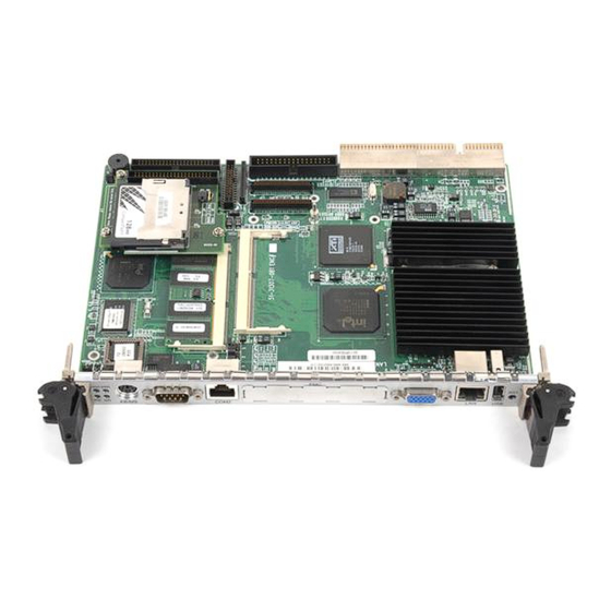
1.4.2 Main Board Drawing Area for HDD installation DIMM 1 DIMM 0 Figure 3. Main Board Drawing Introduction • 5... -
Page 16: Compactpci Bus Interface
1.4.1 CompactPCI Bus Interface The cPCI-6770 operates in a 6U CompactPCI system. The CompactPCI standard is electrically identical to the PCI local bus standard but has been enhanced to work in harsh environments and support more peripheral slots. Additionally, when used in a Hot Swap compliant backplane and in accordance with the CompactPCI Hot Swap Specification, PICMG 2.1, Version 1.0 the cPCI-6770 supports hosting hot swappable peripherals in a powered system. -
Page 17: Pci Mezzanine Card (Pmc) Interface
1.4.4 PCI Mezzanine Card (PMC) Interface The cPCI-6770 provides a location for one on-board PMC device with front panel access. The PMC interface is on the PCI Bus with PMC VIO default factory setting tied to 5V by 0-ohm resistors R28 and R29. If R28 and R29 are removed, and R30 and R31 are installed with 0-ohm resistors, the PMC VIO is 3.3V. -
Page 18: Interrupts
1.4.7 Interrupts Two enhanced interrupt controllers provide the cPCI-6770 with a total of 15 interrupt inputs. Interrupt controller features include support for: • Level-triggered and edge-triggered inputs • Individual input masking • Fixed and rotating priorities Interrupt sources include: • Counter/Timers •... -
Page 19: Power Ramp Circuitry
1.4.10 Power Ramp Circuitry The cPCI-6770 features a power controller with power ramp circuitry to allow the board's voltages to be ramped in a controlled fashion. The power ramp circuitry eliminates any large voltage or current spikes caused by hot swapping boards. -
Page 20: Universal Serial Bus (Usb)
1.4.13 Universal Serial Bus (USB) The Universal Serial Bus (USB) provides a common interface to slower-speed peripherals. Functions such as keyboard, serial ports, printer port, and mouse ports can be consolidated into USB, simplifying the cabling requirements of computers. The cPCI-6770 provides one USB ports on its faceplate and is controlled by the Intel 82371EB (PIIX4E) device. -
Page 21: Chapter 2 Getting Started
Getting Started This chapter summarizes the information needed to make the cPCI-6770 operational. This chapter should be read before using the board. Unpacking Check the shipping carton for any damages. If the shipping carton and contents are damaged, notify the dealer for a replacement. Retain the shipping carton and packing material for inspection by the dealer. -
Page 22: System Requirements
System Requirements The following topics briefly describe the basic system requirements and configurable features of the cPCI-6770. 2.2.1 Connectivity The cPCI-6770 can be installed as a System Master in the System Slot or as a stand-alone computer in a peripheral slot. The cPCI-6770 is designed to operate in a backplane providing CompactPCI form factor interfaces at J1 and 2.2.2 Electrical and Environmental Power Consumption... -
Page 23: Bios Configuration Overview
The cPCI-6770 is supplied with a heatsink allowing the processor to operate between 0º and approximately 55º C ambient with a minimum of 1 meter per second of external airflow. It is the users' responsibility to ensure that the cPCI-6770 is installed in a chassis capable of supplying adequate airflow. The maximum power dissipation of the processor at 850MHz (BGA2 package) is 29W. -
Page 24: Operating System Installation
BIOS Setup Screen Figure 4. BIOS Setup Screen 2.2.6 Operating System Installation For more detailed information about your operating system, refer to the documentation provided by the operating system vendor. Install peripheral devices. CompactPCI devices are automatically configured by the BIOS during the boot sequence. Most operating systems require initial installation on a hard drive, from a floppy or CDROM drive. - Page 25 Proceed with the OS installation as directed, being sure to select appropriate device types if prompted. Refer to the appropriate hardware manuals for specific device types and compatibility modes of ADLINK NuIPC products. When installation is complete, reboot the system and set the boot device order in the SETUP boot menu appropriately.
-
Page 26: Chapter 3 Configuration
Configuration The cPCI-6770 has been designed for maximum flexibility and can be configured for specific applications. Most configuration options are selected through the BIOS Setup utility (discussed in the "BIOS Configuration Overview" topic in Chapter 2). Some options cannot be software controlled and are configured with jumpers or removal of certain zero ohm resistors. -
Page 27: Switch Description
3.1.1 Switch Description SW1 (Reset) SW1 is a push-button on the front panel of the cPCI-6770. Pressing SW1 issues a hard reset. Reset is discussed in more detail in Chapter 4. JP2 (Clear CMOS Content) Setting Function Pin 1-2 Clear CMOS Content Short/Closed Pin 2-3 Normal Operation... -
Page 28: Table 6: Zero Ω Shorting Resistor Settings
Ω Zero Shorting Resistors Ω The cPCI-6770 contains two pairs of zero shorting resistors that allow the user to configure the PMC VIO voltage to either +5V or +3.3V. The PMC interface is on the PCI Bus with PMC VIO default factory setting tied to +5V by 0-ohm resistors R28 and R29. -
Page 29: Chapter 4 Watchdog Timer
Watchdog Timer This chapter explains the operation of the cPCI-6770’s watchdog timer. It provides an overview of watchdog operation and features, as well as a sample code to help you learn how the watchdog timer works. Watchdog Timer Overview The primary function of the watchdog timer is to monitor the cPCI-6770’s operation and take corrective action if the software fails to function as programmed. -
Page 30: Using The Watchdog In An Application
The cPCI-6770's custom watchdog timer circuit is implemented in a programmable logic device. The watchdog timer contains a "Control and Status Register". The register allows the BIOS or user applications to determine if a watchdog time out was the source of a particular reset. The watchdog timer drives the First and Second Stages as follows: The watchdog times out (First Stage) after a selected timeout interval. -
Page 31: Chapter 5 Driver Installation
Driver Installation To install the drivers for the cPCI-6770, refer to the installation information in this chapter. Basic information is presented in this section, however, for more detailed installation information for non-Windows Operating Systems, refer to the extensive explanation inside the ADLINK CD. The drivers are located in the following directories of the CD-Rom: Chipset driver \CHIPDRV\Chipset\440BX... -
Page 32: Vga Driver Installation
VGA Driver Installation This section describes the VGA driver installation for the onboard VGA controller M6-M. relative drivers located X:\CHIPDRV\VGA\ATIM6 of the ADLINK CD, where X: is the drive letter of the CD-ROM drive. The VGA drivers for Windows 95/98, Windows NT and Windows 2000 are included. -
Page 33: Software And Driver Support
5.2.1 Software and Driver Support The 82559 drivers support the following Operating Systems or platforms: • Windows 98, Windows 95, Windows 2000, Windows NT • Novell Netware, DOS Setup for Novell NetWare DOS • UNIX, OS2, Linux All the above drivers are included in the ADLINK CD. In the following section, driver installation for Windows 98, Windows 2000, and Windows NT are outlined. -
Page 34: Lan Driver Installation On Windows 98
5.2.3 LAN Driver Installation on Windows 98 Windows 98 will attempt to install a LAN driver automatically. To guarantee compatibility, manually install the most updated LAN driver, which is stored in the ADLINK’s CD. After installing Windows 98, update to the new driver by following these procedures Boot Windows 98, Click Start. - Page 35 Windows NT may ask to install a LAN driver from its own library of drivers. To guarantee compatibility, manually updated the LAN driver, which comes with the ADLINK CD. After installing Windows NT, update to the new driver by following these procedures. In the Control Panel, double-click on the Network icon, a Network Configuration window will appear.
-
Page 36: Appendix A Specifications
Specifications Electrical This section outlines the electrical specifications of the cPCI-6770 General CompactPCI Features • PICMG 2.0 CompactPCI Rev. 3.0 Compliant • PICMG 2.1 R1.0 CompactPCI Hot Swap Specification Compliant CPU/Cache • Intel BGA2 Pentium III CPU with 256KB on-die L2 cache @ full core speed &... - Page 37 Host Memory • Two 144-pin SODIMM sockets. Max. 512MB PC-100 un-buffered SDRAM • Optional ECC capability support (available for big quantity OEM project) IDE Ports • Bus Master IDE controller supports two 44-pin EIDE interfaces on board for up to four IDE devices •...
- Page 38 On-board VGA Display • ATI’s Mobility Radeon M6-M AGP 4x VGA controller, with built-in 8MB VRAM • ACPI, VESA DPMS and VESA DDC 2b compliant • Supports up to 1600x1200 VGA display resolution with 32-bit true color, non-interlaced • Highly-optimized 128-bit 2D drawing engine, capable of processing multiple pixels/clock •...
-
Page 39: Environment
Front Panel LEDs and switch • Power status (green) • IDE activity indicator (green) • Ethernet port: 10/100Mbps (amber), activity (Green) • Watchdog timer status indicator (green) • Flush tact switch for system reset Environment Storage temperature: -20 to 80ºC Relative Humidity: 5% to 95% non-condensed Shock: 15G peak-to-peak, 11ms duration, non-operation Vibration:... -
Page 40: Mechanical
Mechanical This section describes the board dimensions of the cPCI-6770 Board Dimensions The cPCI-6770 meets the CompactPCI Specification, PICMG 2.0, Version 3.0 for all mechanical parameters. In a CompactPCI enclosure with 0.8 inch spacing, the cPCI-occupies one 6U card slot or two slot depending on model. Mechanical dimensions are shown below. -
Page 41: Connectors
Connectors A detailed description and pin-out for each connector is given in the following section. A.4.1 VGA Connector Signal Name Signal Name Pin 1 Green Blue N.C. Pin 15 N.C. N.C. DDC DATA HSYNC VSYNC DDC CLOCK Table 7: VGA Connector Pin Definition A.4.2 USB Connectors Signal Name Pin 4... -
Page 42: Ethernet (Rj-45) Connector
A.4.3 Ethernet (RJ-45) Connector Signal Name Termination CAP Termination CAP Table 9: Ethernet Connector Pin Definition Amber LED 10/100Mbps Description Status 10Mbps transfer rate 100Mbps transfer rate Table 10: Ethernet Amber LED Status Green LED Link/Activity Description Status No link Connecting Blinking Active/Data transferring... -
Page 43: Parallel Port Connector
A.4.4 Parallel Port Connector Signal Name Signal Name Line printer strobe AutoFeed PD0, parallel data 0 Error PD1, parallel data 1 Initialize PD2, parallel data 2 Select PD3, parallel data 3 PD4, parallel data 4 PD5, parallel data 5 PD6, parallel data 6 PD7, parallel data 7 ACK, acknowledge Busy... -
Page 44: Serial Ports
A.4.6 Serial Ports COM1 Signal Name DCD, Data carrier detect RXD, Receive data TXD, Transmit data DTR, Data terminal ready Pin 6 GND, GND DSR, Data set ready RTS, Request to send CTS, Clear to send RI, Ring indicator Table 14: COM1 Pin Definition COM2 Signal Name DCD, Data carrier detect... -
Page 45: Floppy Connector
A.4.7 Floppy Connector Function Function Ground Extended Density Ground No Connect Data Rate Ground Index Ground Motor A Select Ground Drive B Select Ground Drive A Select Ground Motor B Select Ground Step Direction Ground Step Pulse Ground Write Data Ground Write Gate Ground... -
Page 46: Ide Connector
A.4.8 IDE Connector Signal Signal BRSTDRVJ DDP7 DDP8 DDP6 DDP9 DDP5 DDP10 DDP4 DDP11 DDP3 DDP12 DDP2 DDP13 DDP1 DDP14 DDP0 DDP15 PDDREQ PDIOWJ PDIORJ PIORDY PCSEL PDDACKJ IRQ14 DAP1 DAP0 DAP2 CS1P CS3PJ IDEACTPJ Table 17: IDE Connector Pin Definition 36 •... -
Page 47: Pmc Connectors
A.4.9 PMC Connectors Signal Signal -12V INTA# INTB# INTC# BUSMODE1# INTD# RESERVED +3.3V CLOCK GNT# REQ# PMCVIO AD[31] AD[28] AD[27] AD[25] C/BEJ[3]# AD[22] AD[21] AD[19] PMCVIO AD[17] FRAME# IRDY# DEVSEL# LCOK# RESERVED RESERVED PMCVIO AD[15] AD[12] AD[11] AD[9] C/BEJ[0]# AD[6] AD[5] AD[4] PMCVIO... -
Page 48: Table 19: Pmc J12 Pin Definition
Signal Signal +12V TRST# RESERVED RESERVED RESERVED RESERVED BUSEMODE2# +3.3V PCI RESET BUSMODE3# +3.3V BUSMODE4# AD[30] AD[29] AD[26] AD[24] +3.3V IDSEL (AD[31]) AD[23] +3.3V AD[20] AD18 AD16 C/BEJ[2]# RESERVED TRDY# +3.3V STOP# PERR# +3.3V SERR# C/BEJ[1]# AD[14] AD13 AD10 AD[8] +3.3V AD[7] RESERVED... -
Page 49: Compactpci Connectors
A.4.10 CompactPCI Connectors +3.3V REQ64# ENUM# AD[1] AD[0] ACK64# +3.3V AD[4] AD[3] AD[2] AD[7] +3.3V AD[6] AD[5] +3.3V AD[9] AD[8] C/BE[0]# AD[12] AD[11] AD[10] +3.3V AD[15] AD[14] AD[13] SERR# +3.3V C/BE[1]# +3.3V SMSCL SMSDA PERR# DEVSEL# STOP# LOCK# +3.3V FRAME# IRDY# TRDY# 12-14... -
Page 50: Table 21: Compactpci J2 Pin Definition
S1CLK6 S1CLK5 PRST# S1REQ#6 S1GNT#6 DEG# FAL# S1REQ#5 S1GNT#5 S1CLK4 S1GNT#3 S1REQ#4 S1GNT#4 S1CLK2 S1CLK3 SYSEN# S1GNT#2 S1REQ#3 S1CLK1 S1REQ#1 S1GNT#1 S1REQ#2 Table 21: CompactPCI J2 Pin Definition These signals are not connected. These signals are pulled high on the board. These signals are pulled low on board. -
Page 51: Thermal Consideration
Thermal Consideration This section of the appendix describes the thermal requirements for reliable operation of a cPCI-6770 using the Pentium III processor. It covers basic thermal requirements and provides specifics about monitoring the board and processor temperature. A.5.1 Thermal Requirements The cPCI-6770 is factory-equipped with an integrated heatsink for cooling the processor module. -
Page 52: Safety Certificate And Test
Safety Certificate and Test This section presents approval and certification information for the cPCI-6770 with Intel Pentium III Processor. The cPCI-6770 is designed to meet the specifications listed in this section A.6.1 CE Certification The cPCI-6770 is designed to meet the intent of Directive 89/336/EEC for Electromagnetic Compatibility. -
Page 53: Warranty Policy
Warranty Policy Thank you for choosing ADLINK. To understand your rights and enjoy all the after-sales services we offer, please read the following carefully: Before using ADLINK’s products please read the user manual and follow the instructions exactly. When sending in damaged products for repair, please attach an RMA application form.
Need help?
Do you have a question about the NuIPC cPCI-6770 Series and is the answer not in the manual?
Questions and answers