Omron K3HB-R Manual
Digital indicators
Hide thumbs
Also See for K3HB-R:
- Datasheet (33 pages) ,
- User manual (183 pages) ,
- User manual (186 pages)
Table of Contents
Advertisement
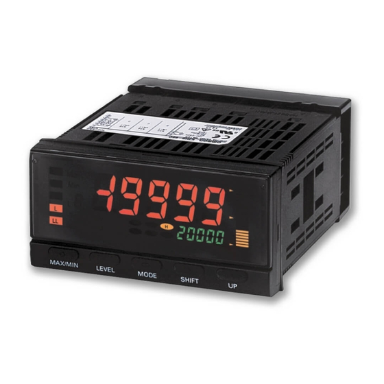
Digital Indicators
K3HB Series (Pulse Input Series)
The K3HB Series has been made complete with
the addition of Digital Signal Input Models.
• Easy recognition of judgment results using two-color
display that can be switched between red and green.
• Equipped with a position meter for monitoring
operating status trends.
• External event inputs allows using various
measurement and discrimination applications.
• Series expanded to include DeviceNet models.
• Short body with depth of only 95 mm (see note)
(from behind the front panel).
• UL certification (Certification Mark License).
• CE Marking conformance by third party assessment
body.
• Water-resistant enclosure conforms to NEMA 4X
(equivalent to IP66).
Note: Depth of 97 mm for DeviceNet models.
Refer to Common Precautions on page 30.
Features
Red-Green Display Allows Easy
Recognition of Judgment Results
The measurement value display can be set to switch between red
and green in accordance with the status of comparative outputs. This
means that the status can be easily seen at a distance.
Position Meter Enables Easy Monitoring of
Operating Status Trends
The present value with respect to the measurement or display range
(full scale) can be viewed on a bar display. The operating status can
be grasped intuitively, allowing easy judgment of levels and threshold
values.
HH
Max
Min
H
B
P
L
L
CMW
HH
LL
Hold
T
LL
MAX/MIN
LEVEL
MODE
Note: This function is different from the single-LED display of the K3HB-C.
Short Body with Depth of Only 95 mm
(from Behind the Front Panel)
A short body of only 95 mm (see note) contributes to the
development of slimmer and smaller control panels and installations.
95 mm
Depth:
(See note.)
(The depth is 100 mm when mounted to the terminal cover.)
Note: Depth of DeviceNet models is 97 mm.
Position meter
H
L
SHIFT
UP
27%
shorter
than earlier
models
Digital Indicators
50 kHz High-speed Pulse Measurement
(K3HB-R)
Supports high-speed pulse measurement (up to 50 kHz) of rotary
encoders or any ON/OFF pulse signal, which enables rotational
measurement of objects rotating at high speeds.
Note: No-voltage contacts of up to 30 Hz are supported.
Measurement of Wide Range of Pulse
Interval Times (K3HB-P)
Measures and displays the results of the pulse interval between two
points. The pulse interval measurement range is broad, from 10 ms
to 3,200 s.
High-speed Up/Down Counting Pulse
Measurement (K3HB-C)
Perfect for high-speed measurement of rotary encoders or any
ON/OFF pulse signals. Cumulative pulse input is 50 kHz, quadrature
pulse inputs are 25 kHz, and up/down pulse inputs are 30 kHz.
Note: No-voltage contacts of up to 30 Hz are supported.
K3HB Series (Pulse Input Series)
50 kHz
50 kHz
10 ms to 3200 s
1
Advertisement
Table of Contents

Related Manuals for Omron K3HB-R


Summary of Contents for Omron K3HB-R
- Page 1 Red-Green Display Allows Easy 50 kHz High-speed Pulse Measurement Recognition of Judgment Results (K3HB-R) The measurement value display can be set to switch between red Supports high-speed pulse measurement (up to 50 kHz) of rotary and green in accordance with the status of comparative outputs. This encoders or any ON/OFF pulse signal, which enables rotational means that the status can be easily seen at a distance.
- Page 2 Digital Indicators are used in a wide variety of applications, from an electronic measurement value display or equipment/device operating status display to a host communications interface in monitoring and control systems. OMRON provides a complete lineup for a variety of input and control output applications to meet all your application requirements.
- Page 3 In addition, contact your nearest OMRON representative and confirm specifications. K3HB-series Product Lineup ■ K3HB-R Rotary Pulse Indicator (Page 4) Performs High-speed Rotation Measurement Displaying Bread Baking Time...
-
Page 4: Model Number Structure
Model Number Structure ■ Model Number Legend Base Units and Optional Boards can be ordered individually or as sets. Base Units Base Units with Optional Boards K3HB-R @ K3HB-R@-@@@ 2 3 4 2. Sensor Power Supply/Output Type Codes 1. Input Sensor Codes... -
Page 5: Specifications
Note: 1. DC power supply models require a control power supply capacity of approximately 1 A per Unit when power is turned ON. Particular attention is required when using two or more DC power supply models. The OMRON S8VS-series DC Power Supply Unit is recommended. - Page 6 Conducted Disturbance Immunity EN61000-4-6: 3 V (0.15 to 80 MHz) Power Frequency Magnetic Immunity EN61000-4-8: 30 A/m (50 Hz) continuous time Voltage Dips and Interruptions Immunity EN61000-4-11: 0.5 cycle, 0 ° /180 °, 100% (rated voltage) K3HB-R Rotary Pulse Indicator...
-
Page 7: Operation
Display value D = ƒa × 60 × α N = Pulses per rotation π d = Circumferential length per rotation K3HB-R Rotary Pulse Indicator... - Page 8 Display unit Prescale value ( α ) Calculation L/( π d/N) Distance Passing time PASS N = Pulses per rotation π d = Circumferential length per rotation (m) Warning L = Length of process (m) output K3HB-R Rotary Pulse Indicator...
- Page 9 Set the auto-zero time to slightly longer than the longest input pulse interval. (The display will not easily return to zero if the auto-zero time is too long or left at the default setting.) K3HB-R Time Unit Settings Proximity...
- Page 10 Timer Interval Indicator K3HB-P Digital Time Interval Meter for Measuring Passing Speed, Time, or Cycle between Two Points. • Measures Wide Range of Pulse Interval Times Measures, calculates, and displays pulse intervals between two points. Wide range for pulse interval measurements, from 10 ms to 3,200 s, max.
- Page 11 Note: 1. DC power supply models require a control power supply capacity of approximately 1 A per Unit when power is turned ON. Particular attention is required when using two or more DC power supply models. The OMRON S8VS-series DC Power Supply Unit is recommended.
- Page 12 ■ Characteristics − 19,999 to 99,999 Display range Measurement accuracy ±0.08% rgd ±1 digit (for voltage pulse/open collector sensors) (at 23±5 ° C) Measurement range Functions F1, F3, and F4:10 ms to 3,200 s Function F2: 20 ms to 3,200 s Functions F5 and F6: 0 to 4 gigacounts Input signals...
- Page 13 Operation ■ Functions (Operating Modes) F1 to F6 These functions use the internal system clock to measure the time between pulses or the pulse ON time and then display time measurements or a variety of other calculations. Example: F1 Passing Speed The time (T) between input A pulse and input B pulse is measured by the internal system clock.
- Page 14 Function Operation Operation image (application) Displays input A ON time (T). Monitoring the ON time of a printing Managing the valve release Time band press time Input A Communications HOLD input output Display Measurement range: 10 ms to 3,200 s •...
- Page 15 Up/Down Counting Pulse Indicator K3HB-C Measure High-speed Up/down Pulses with this Up/down Pulse Meter. • Perfect for Measuring Rotary Encoder and ON/OFF Pulse Signals at High Speed Cumulative pulse input is 50 kHz, quadrature pulse inputs are 25 kHz, and up/down pulse inputs are 30 kHz. Note: No-voltage contacts of up to 30 Hz are supported.
- Page 16 Note: 1. DC power supply models require a control power supply capacity of approximately 1 A per Unit when power is turned ON. Particular attention is required when using two or more DC power supply models. The OMRON S8VS-series DC Power Supply Unit is recommended.
- Page 17 ■ Characteristics − 19,999 to 99,999 Display range Measurement range Functions F1, F2: ±2 gigacounts Functions F3 : 0 to 4 gigacounts Input signals • No-voltage contact (30 Hz max. with ON/OFF pulse width of 15 ms min.) • Voltage pulse Mode Input frequency ON/OFF...
- Page 18 Operation ■ Functions (Operating Modes) F1 to F3 Function name Function No. Individual inputs Phase differential inputs f2 Pulse counting input Function Operation Operation image (application) Counts input A as incremental pulses and input B as Counting the number of people entering an area Individual decremental pulses.
- Page 19 ■ What Is Prescaling? Prescaling converts the count value to any numeric value. To display @@@@.@ mm in a system that outputs 250 pulses for a 0.5-m feed, the length per pulse = 500 mm (0.5 m) ÷ 250 = 2. 1.
-
Page 20: Common Specifications
Common Specifications ■ Event Input Ratings K3HB-R S-TMR, HOLD, RESET, BANK1, BANK2, BANK4 K3HB-P/-C HOLD, RESET, BANK1, BANK2, BANK4 ON: 1 k Ω max., OFF: 100 k Ω min. Contact No-contact ON residual voltage: 2 V max. OFF leakage current: 0.1 mA max. -
Page 21: Devicenet Communications
Current consumption 50 mA max. (24 VDC) Maximum number of nodes 64 (DeviceNet Configurator is counted as one node when connected.) Maximum number of slaves Error control checks CRC errors DeviceNet power supply Supplied from DeviceNet communications connector K3HB-R/-P/-C Digital Indicators... -
Page 22: Terminal Arrangements
(HONDA TSUSHIN KOGYO CO., LTD.) 80 mA 80 mA supply − Special Cable (Sold separately) K32-BCD (OMRON) <L2A> <L1A> (HDR-E50MAG1 with 0.3-m cable) Sensor power supply The BCD COMMON is shared. The pins indicated in the above diagram as blank (white) boxes have been removed. - Page 23 • Special Cable (Sold separately) COMPENSATION K32-DICN (OMRON) 3.9 kΩ (XG4M-1030 with 3-m cable) The following signals depend on the model: S-TMR: Used by the K3HB-R only. COMPENSATION: Used by the K3HB-C only. BCD Output Cable Model Shape Pin arrangement...
- Page 24 Relay output circuit circuit shaping circuit Drive Linear output Drive DeviceNet Linear output DeviceNet circuit circuit circuit circuit Communi- Drive Sensor power Filter cations Communications supply circuit driver DC-DC Power supply circuit (isolated) Converter (isolated) Power supply K3HB-R/-P/-C Digital Indicators...
-
Page 25: Continuous Data Output
Refer to the following User's Manual for application precautions and other information required when using the Digital Indicator: K3HB-R/P/C Digital Indicator User's Manual (Cat. No. N136) The manual can be downloaded from the following site in PDF format: OMRON Industrial Web http://www.fa.omron.co.jp K3HB-R/-P/-C... - Page 26 Hold Status indicators SV display status indicators MAX/MIN LEVEL MODE SHIFT K3HB-R Display Function Indicator Function Lit when communications writing is ON (enabled) and not lit when OFF (prohibited). Turns ON when parameters for which teaching can be performed are Turns ON/OFF when hold input turns displayed.
- Page 27 Waterproof Packing The waterproof packing ensures a level of waterproofing that conforms to NEMA 4X. Depending on the operating environment, deterioration, contraction, or hardening may occur and replacement may be necessary. In this case, consult your OMRON representative. K3HB-R/-P/-C Digital Indicators...
-
Page 28: Main Functions
R P C Function Auto-zero Times The K3HB-R has the following six functions for receiving and The frequency is forced to zero if there is no pulse input for a set displaying input pulses. period. F1: Rotation (rpm)/circumferential speed... - Page 29 The comparison outputs can be kept OFF until the measurement value enters the PASS range. memo Interruption Memory The measured value can be recorded when the power supply is interrupted. R P C User Calibration The K3HB can be calibrated by the user. K3HB-R/-P/-C Digital Indicators...
-
Page 30: Precautions For Safe Use
DeviceNet communications distances. Refer resulting in minor or moderate injury, or damage to the to the User's Manual (Cat. No. N129) for details on equipment. communications distance specifications and cables. K3HB-R/-P/-C Digital Indicators... - Page 31 4. If a noise filter is used for the power supply, check the voltage and current, and install the noise filter as close to the product as possible. 5. Reception interference may occur if the product is used close to a radio, television, or wireless. K3HB-R/-P/-C Digital Indicators...
-
Page 32: Warranty And Limitations Of Liability
Warranty and Limitations of Liability ■ WARRANTY OMRON's exclusive warranty is that the products are free from defects in materials and workmanship for a period of one year (or other period if specified) from date of sale by OMRON. OMRON MAKES NO WARRANTY OR REPRESENTATION, EXPRESS OR IMPLIED, REGARDING NON-INFRINGEMENT, MERCHANTABILITY, OR FITNESS FOR PARTICULAR PURPOSE OF THE PRODUCTS.
Need help?
Do you have a question about the K3HB-R and is the answer not in the manual?
Questions and answers