Mitsubishi FX3UC SERIES User Manual
Hide thumbs
Also See for FX3UC SERIES:
- Operation manual (106 pages) ,
- Manual (13 pages) ,
- Programming manual (944 pages)
Table of Contents
Advertisement
Quick Links
Advertisement
Chapters
Table of Contents
Troubleshooting

Related Manuals for Mitsubishi FX3UC SERIES


Summary of Contents for Mitsubishi FX3UC SERIES
- Page 1 USER'S MANUAL - Hardware Edition SERIES PROGRAMMABLE CONTROLLERS...
- Page 3 Safety Precaution (Read these precautions before using.) Before installing, operating, maintenance or inspecting this product, thoroughly should be read and understood this manual and the associated manuals. Also pay careful attention to safety and handle the module properly. This manual classify the safety precautions into two categories: Indicates that incorrect handling may cause hazardous conditions, resulting in death or severe injury.
- Page 4 Safety Precaution (Read these precautions before using.) 2. INSTALLATION PRECAUTIONS Reference • Make sure to cut off all phases of the power supply externally before attempting installation or wiring work. Failure to do so may cause electric shock or damage to the product. Reference •...
-
Page 5: Table Of Contents
Safety Precaution (Read these precautions before using.) 3. WIRING PRECAUTIONS Reference • Make sure to cut off all phases of the power supply externally before attempting installation or wiring work. Failure to do so may cause electric shock or damage to the product. •... - Page 6 • Do not disassemble or modify the PLC. Doing so may cause fire, equipment failures, or malfunctions. For repair, contact your local Mitsubishi Electric distributor. • Turn off the power to the PLC before connecting or disconnecting any extension cable.
-
Page 7: Safety Precautions
This manual confers no industrial property rights or any rights of any other kind, nor does it confer any patent licenses. Mitsubishi Electric Corporation cannot be held responsible for any problems involving industrial property rights which may occur as a result of using the contents noted in this manual. -
Page 8: Program Example
• Since the examples indicated by this manual, technical bulletin, catalog, etc. are used as a reference, please use it after confirming the function and safety of the equipment and system. Mitsubishi Electric will accept no responsibility for actual use of the product based on these illustrative examples. -
Page 9: Program Example
Series Programmable Controllers User's Manual - Hardware Edition Table of Contents Table of Contents SAFETY PRECAUTIONS ....................(1) Standards..........................13 Certification of UL, cUL standards ....................... 13 Compliance with EC directive (CE Marking) ..................14 Requirement for Compliance with EMC directive ..................14 Requirement for Compliance with LVD directive .................. - Page 10 Series Programmable Controllers User’s Manual - Hardware Edition Table of Contents 2. External Dimensions and Terminal Arrangement 2.1 External Dimensions (MASS/Installation/Accessories) ..............78 2.1.1 Main Units............................78 2.1.2 FX Series Input/output Extension Block................... 79 2.1.3 FX Series Input/output Extension Block..................80 2.1.4 FX Series Input/output Extension Block..................
- Page 11 Series Programmable Controllers User's Manual - Hardware Edition Table of Contents 4. Power Supply Specifications and External wiring 4.1 Selection of the external DC power supply to prepare..............130 4.1.1 Power supply specifications ......................130 4.1.2 The input range of power supply voltage..................131 4.1.3 Power consumption of the extension equipment.................
- Page 12 Series Programmable Controllers User’s Manual - Hardware Edition Table of Contents 7. Examples of Wiring for Various Uses 7.1 Notes about Examples of Wiring....................187 7.2 Rotary Encoder [High-speed Counters C235 to C255] ............... 188 7.2.1 1-phase 1-input [C235 to C245] ....................188 7.2.2 2-phase 2-input [C251 to C255] ....................
- Page 13 Series Programmable Controllers User's Manual - Hardware Edition Table of Contents 8.11 FX-16EYT-ES-TB/UL ........................ 238 8.11.1 Specifications ..........................238 8.11.2 Internal circuit ..........................239 8.11.3 Example of output external wiring ..................... 239 8.11.4 External wiring precautions ....................... 239 8.12 FX-16EYT-ESS-TB/UL......................240 8.12.1 Specifications ..........................
- Page 14 Series Programmable Controllers User’s Manual - Hardware Edition Table of Contents 9.9 Setting of CC-Link/LT built-in master and remote I/O units............280 9.9.1 Setting DIP switches in built-in master (operation mode/Communication speed/Point mode) ............281 9.9.2 Station number setting of the remote I/O units ................282 9.9.3 The start of the operation ......................
- Page 15 Series Programmable Controllers User's Manual - Hardware Edition Table of Contents 10. Display Module (Only FX -32MT-LT) 10.1 Specifications ..........................319 10.1.1 Display specifications ........................ 319 10.1.2 Operation button list ........................319 10.2 Summary of Functions ......................320 10.3 Procedure for Accessing the Menu Screen from the Title Screen ..........321 10.3.1 Title screen ..........................
- Page 16 Series Programmable Controllers User’s Manual - Hardware Edition Table of Contents 10.19 Operation Button ON/OFF Information ................... 357 10.19.1 Various applications ........................ 357 10.19.2 System information - operation button ON/OFF information ........... 357 10.20 User (User-Registered Device Setting)................... 358 10.20.1 System information - user-registered device setting ............... 358 10.20.2 Precaution when setting 3 or fewer devices ................
- Page 17 Series Programmable Controllers User's Manual - Hardware Edition Table of Contents 12.4 Maintenance..........................389 12.4.1 Periodic inspection ........................389 12.4.2 Product life of relay contacts ..................... 389 12.4.3 Procedures for replacing battery ....................391 12.5 Troubleshooting with LEDs ....................... 392 12.5.1 POW LED [on/flashing/off]......................
- Page 18 Series Programmable Controllers User’s Manual - Hardware Edition Table of Contents Appendix D: Instruction List Appendix D-1 Basic Instructions ....................441 Appendix D-2 Step Ladder Instructions ..................441 Appendix D-3 Applied Instructions ... in Ascending Order of FNC Number......442 Appendix E: Character-code Appendix E-1 ASCII Code Table ....................
-
Page 19: Standards
Standards Certification of UL, cUL standards main units and FX input/output extension units/blocks supporting UL, cUL standards are as follows: UL, cUL file number :E95239 Models : MELSEC FX series manufactured 3U(C) MT/D MT/DSS Where indicates:16,32,64,96 -232ADP(-MB) -485ADP(-MB) -4AD-ADP -4DA-ADP -4AD-PT-ADP -4AD-TC-ADP -1PS-5V... -
Page 20: Compliance With Ec Directive (Ce Marking)
Compliance to EMC directive and LVD directive of the entire mechanical module should be checked by the user / manufacturer. For more details please contact to the local Mitsubishi Electric sales site. Requirement for Compliance with EMC directive... - Page 21 Models : MELSEC FX series manufactured from March 1st, 1999 EX-DS EYT-DSS Where indicates:16,32 from August 1st, 1999 -16EX-T-DS -16EYR-T-DS from October 1st, 2007 Where indicates:16,32 -16EX-T -16EYR-T Standard Remark EN61000-6-4:2001 - Generic emission standard Compliance with all relevant aspects of the standard. Industrial environment •...
- Page 22 Models : MELSEC FX series manufactured from July 1st, 1997 -16EX-ES/UL -16EYR-ES/UL -16EYT-ESS/UL from August 1st, 2005 -8ER-ES/UL -8EX-ES/UL -8EYR-ES/UL -8EYT-ESS/UL For the products above, PLCs manufactured before March 31st, 2002 are compliant with EN50081-2 (EN61000-6-4) and EN50082-2 from April 1st, 2002 to April 30th, 2006 are compliant with EN50081-2 (EN61000-6-4) and EN61131-2:1994 +A11:1996+A12:2000 after May 1st, 2006 are compliant with EN61131-2:2003 Standard...
-
Page 23: Requirement For Compliance With Lvd Directive
Requirement for Compliance with LVD directive The following products have shown compliance through direct testing (of the identified standards below) and design analysis (through the creation of a technical construction file) to the European Directive for Low Voltage (73/23/EEC) when used as directed by the appropriate documentation. Type : Programmable Controller (Open Type Equipment) Models :... -
Page 24: Caution For Compliance With Ec Directive
(integral with sensors or actuators), these users should follow those manufacturers' installation requirements. Mitsubishi Electric recommends that shielded cables be used. If NO other EMC protection is provided, users may experience temporary loss or accuracy between +10% / -10% in very heavy industrial areas. -
Page 25: Associated Manuals
Series Programmable Controllers User’s Manual - Hardware Edition Associated Manuals Associated Manuals Series PLC main units supplied only with the hardware manual. For the details of the hardware of FX Series, refer to this manual. For instructions for programming and hardware information on special function devices, refer to the relevant manuals. - Page 26 Series Programmable Controllers User’s Manual - Hardware Edition Associated Manuals : Indispensable manuals : Manuals necessary for some purposes : Manuals with separate volumes for details Manual Model Manual Name Description Number Code RS-232C/RS-422/RS-485/USB communication When using each product, refer also to the User's Manual - Hardware Edition for the PLC main unit to be installed. System configuration of the USB Supplied communication expansion board and...
- Page 27 Series Programmable Controllers User’s Manual - Hardware Edition Associated Manuals : Indispensable manuals : Manuals necessary for some purposes : Manuals with separate volumes for details Manual Model Manual Name Description Number Code CC-Link, CC-Link/LT, MELSEC I/O LINK, and AS-i system When using each product, refer also to the User's Manual - Hardware Edition for the PLC main unit to be installed.
- Page 28 Series Programmable Controllers User’s Manual - Hardware Edition Associated Manuals : Indispensable manuals : Manuals necessary for some purposes : Manuals with separate volumes for details Manual Model Manual Name Description Number Code Supplied -4AD Procedures for handling the 4-ch analog with JY997D07801 User's Manual...
- Page 29 Series Programmable Controllers User’s Manual - Hardware Edition Associated Manuals : Indispensable manuals : Manuals necessary for some purposes : Manuals with separate volumes for details Manual Model Manual Name Description Number Code Manuals for positioning control High-speed counter When using each product, refer also to the User's Manual - Hardware Edition for the PLC main unit to be installed. Supplied -1HC Procedures for handling the 1-ch high-speed...
- Page 30 Series Programmable Controllers User’s Manual - Hardware Edition Associated Manuals : Indispensable manuals : Manuals necessary for some purposes : Manuals with separate volumes for details Manual Model Manual Name Description Number Code Connector conversion Procedures for handling the conversion Supplied -CNV-BD function expansion board for connectors for...
-
Page 31: Generic Names And Abbreviations Used In Manuals
Series Programmable Controllers User’s Manual - Hardware Edition Generic Names and Abbreviations Used in Manuals Generic Names and Abbreviations Used in Manuals Generic Name and Description Abbreviation PLCs Series Generic name for FX Series PLCs Series Generic name for FX Series PLCs Series Generic name for FX... - Page 32 Series Programmable Controllers User’s Manual - Hardware Edition Generic Names and Abbreviations Used in Manuals Generic Name and Description Abbreviation Generic name for the following models FX-16E-TB, FX-32E-TB, FX-16EX-A1-TB, FX-16EYR-TB, FX-16EYT-TB, FX Series terminal blocks FX-16EYT-H-TB, FX-16EYS-TB, FX-16E-TB/UL, FX-32E-TB/UL, FX-16EYR-ES-TB/UL, FX-16EYT-ES-TB/UL, FX-16EYT-ESS-TB/UL, FX-16EYS-ES-TB/UL Generic name for the following models Extension cables...
- Page 33 Series Programmable Controllers User’s Manual - Hardware Edition Generic Names and Abbreviations Used in Manuals Generic Name and Description Abbreviation Manuals Abbreviation of FX Series Programming Manual - Basic & Applied Programming manual Instructions Data Communication Edition Abbreviation of FX Series User's Manual - Data Communication Edition Analog Control Edition Abbreviation of FX Series User's Manual - Analog Control Edition...
-
Page 34: Outline
Series Programmable Controllers 1 Outline User’s Manual - Hardware Edition 1.1 Major Features Outline Major Features 1. Basic functions [Remote debugging of program] Programming software enables you to remotely [Up to 384 input/output points] transfer the program and monitor the PLC 384 points in total include input/output points in operation through a modem connected to the the PLC (adjacent direct wiring) and remote... - Page 35 Series Programmable Controllers 1 Outline User’s Manual - Hardware Edition 1.1 Major Features [Input interruption function (with delay • Computer link → Refer to the Data Communication Edition. function)] Interruption routines processed • No-protocol communication through RS- preferentially by external signals with a minimum 232C/RS-485 ON or OFF width of 5 µs (X000 to X005).
-
Page 36: Part Names
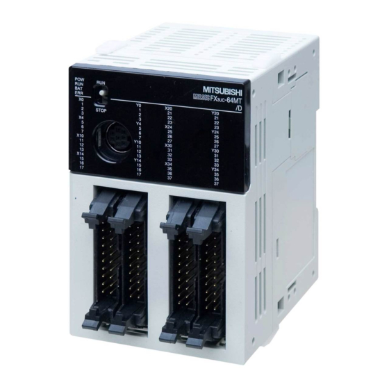
Series Programmable Controllers 1 Outline User’s Manual - Hardware Edition 1.2 Part names Part names 1.2.1 MT/D, DSS [10] [10] [17] [16] [18] [15] [11] [12] [20] [14] [13] [10] [17] [10] [21] [10] [22] Description Description Display LEDs Memory cassette dummy cover Memory cassette or Memory Green cassette dummy cover... -
Page 37: Fx 3Uc -32Mt-Lt
Series Programmable Controllers 1 Outline User’s Manual - Hardware Edition 1.2 Part names Description Description Extension block connecting [19] Extension block connector connector cover [20] Nameplate [21] Power connector for main unit Extension block connector cover [22] Battery cover [18] [19] 1.2.2 -32MT-LT... - Page 38 Series Programmable Controllers 1 Outline User’s Manual - Hardware Edition 1.2 Part names Description Description [12] "ESC" button Memory cassette dummy cover [13] "-" button [14] "+" button Memory cassette or Memory cassette dummy cover [15] "OK" button DIP switches for setting CC-Link/LT master [16] function Display LEDs...
-
Page 39: Interpretation Of Model Names (Main Units, I/O Extension Blocks)
Series Programmable Controllers 1 Outline User’s Manual - Hardware Edition 1.3 Interpretation of Model Names (Main Units, I/O Extension Blocks) Interpretation of Model Names (Main Units, I/O Extension Blocks) Series Classifi Total number Classifi Input/ name cation1 of I/O points output cation2 type... -
Page 40: List Of Products
Series Programmable Controllers 1 Outline User’s Manual - Hardware Edition 1.4 List of Products List of Products 1. FX MT/D Memory cassettes Main units Extension Extension Blocks Extension power supply -FLROM-16 -16MT/D Blocks unit -FLROM-64 -8EX -32MT/D -16EX -FLROM-64L -1PS-5V -8EX-UA1/UL -64MT/D -16EX-T... - Page 41 Series Programmable Controllers 1 Outline User’s Manual - Hardware Edition 1.4 List of Products 3. FX -32MT-LT Extension Memory cassettes Main units power supply Extension -FLROM-16 Extension unit Blocks -FLROM-64 Blocks -1PS-5V -FLROM-64L -32MT-LT -16EX -8EX connector -16EX-T -8EX-UA1/UL Expansion boards conversion -16EYT -8ER...
-
Page 42: Main Units
Series Programmable Controllers 1 Outline User’s Manual - Hardware Edition 1.4 List of Products 1.4.1 Main units Input Output Number Current Drive Connecting of input/ Capacity Model name power type output 5V DC Points Type Points Type supply points (mA) 24V DC Transistor -16MT/D... - Page 43 Series Programmable Controllers 1 Outline User’s Manual - Hardware Edition 1.4 List of Products 2. FX Series I/O Extension Blocks When connected to one of the FX I/O extension blocks listed in the following table, the FX CNV-IF or FX -1PS-5V is required.
-
Page 44: Special Function Units/Blocks
Series Programmable Controllers 1 Outline User’s Manual - Hardware Edition 1.4 List of Products Input Output Number 5V DC current Connecting of input/ Model name consumption type output Points Type Points Type (mA) points Terminal -16EYR Relay block Transistor Terminal -16EYT (sink) block... - Page 45 Series Programmable Controllers 1 Outline User’s Manual - Hardware Edition 1.4 List of Products 2. High-speed counter When connected to the special function blocks in the following table, the FX -CNV-IF or FX -1PS- 5V is required. Number 5V DC current of input/ Model name Description...
- Page 46 Series Programmable Controllers 1 Outline User’s Manual - Hardware Edition 1.4 List of Products 4. Data link and communication functions When connected to the special function blocks in the following table, the FX -CNV-IF or FX -1PS- 5V is required. Number 5V DC current of input/...
-
Page 47: Expansion Boards
Series Programmable Controllers 1 Outline User’s Manual - Hardware Edition 1.4 List of Products 1.4.4 Expansion boards 1. Communication functions Number 5V DC current of input/ Model name Description consumption output (mA) points -CNV-BD Conversion of connector for fitting special adapter -232-BD For RS-232C communication For RS-422 communication... -
Page 48: Extension Power Supply Unit
Series Programmable Controllers 1 Outline User’s Manual - Hardware Edition 1.4 List of Products 1.4.6 Extension power supply unit Model name Description Drive power supply Current Capacity DC -1PS-5V 5V DC extension power supply 24V DC 5V DC 1A 1.4.7 Connector conversion adapter 5V DC current Model name... -
Page 49: Fx Series Terminal Blocks
Series Programmable Controllers 1 Outline User’s Manual - Hardware Edition 1.4 List of Products 1.4.9 FX Series terminal blocks Drive power Model name Input points Output points Function supply 16 input points or FX-16E-TB 16 output points To be directly connected to the PLC 32 input points, input/output connector 32 output points or... -
Page 50: Input/Output Cable • Input/Output Connector • Power Cable
Series Programmable Controllers 1 Outline User’s Manual - Hardware Edition 1.4 List of Products A power supply for the input circuit is required when connected to the FX -16EX-C. The current consumption is shown in the table below. Power Supply Voltage Current Consumption MT/D, FX 32MT-LT, FX... -
Page 51: Connection To Programming Tool
Series Programmable Controllers 1 Outline User’s Manual - Hardware Edition 1.5 Connection to programming tool Connection to programming tool RS-232C/RS-422 cable Connection cabling Connection cabling for extension devices Peripheral device connector FX-232AWC-H RS-422 RS-232C FX-USB-AW Special adapter -232ADP(-MB) RS-232C -232ADP POW ER Expansion board -232-BD... -
Page 52: System Overall Configuration
Series Programmable Controllers 1 Outline User’s Manual - Hardware Edition 1.6 System overall configuration System overall configuration Products connectable to the FX PLC are classified into the groups as shown below. For model names of products classified into the groups, refer to "1.11 Number of input/output occupied points and 5V DC current consumption of each model". -
Page 53: Rules Of System Configuration
Series Programmable Controllers 1 Outline User’s Manual - Hardware Edition 1.7 Rules of System Configuration Rules of System Configuration The system configuration must meet the following four requirements. 1. Number of input/output points In the FX -32MT-LT Ver.2.20 or later, FX MT/D and FX MT/DSS, up to 384 points are available in total including input/output points of the PLC and remote input/output points in the CC-Link or... - Page 54 Series Programmable Controllers 1 Outline User’s Manual - Hardware Edition 1.7 Rules of System Configuration 2. 5V DC power supply capacity (current consumption) The main unit buit-in power supply and the extension power supply unit supply power to extension equipment respectively.
-
Page 55: Number Of Input/Output Points And Maximum Number Of Input/Output Points
Series Programmable Controllers 1 Outline User’s Manual - Hardware Edition 1.8 Number of Input/Output Points and Maximum Number of Input/Output Points Number of Input/Output Points and Maximum Number of Input/Output Points The number of input/output points and maximum number of input/output points varies depending on the PLC version and network type. - Page 56 Series Programmable Controllers 1 Outline User’s Manual - Hardware Edition 1.8 Number of Input/Output Points and Maximum Number of Input/Output Points • FX -1RM(-SET), FX -1RM-E(-SET) Up to 3 units can be sequentially connected to the end of a system. However, when three units are connected, they are counted as a unit, and the number of input/output occupied points is 8.
-
Page 57: Maximum Number Of Input/Output Points When Cc-Link Master Is Used
Series Programmable Controllers 1 Outline User’s Manual - Hardware Edition 1.8 Number of Input/Output Points and Maximum Number of Input/Output Points 1.8.2 Maximum number of input/output points when CC-Link master is used 1. Calculation of maximum number of input/output points The maximum number of available input/output points is as follows when the FX -32MT-LT Ver. -
Page 58: Maximum Number Of Input/Output Points When As-I Master Is Used
Series Programmable Controllers 1 Outline User’s Manual - Hardware Edition 1.8 Number of Input/Output Points and Maximum Number of Input/Output Points 1.8.3 Maximum number of input/output points when AS-i master is used 1. Calculation of maximum number of input/output points The maximum number of input/output points available is as follows when the FX -32MT-LT Ver. -
Page 59: Calculation Of 5V Dc Power Supply Capacity (Current Consumption)
Series Programmable Controllers 1 Outline User’s Manual - Hardware Edition 1.9 Calculation of 5V DC power supply capacity (current consumption) Calculation of 5V DC power supply capacity (current consumption) Confirm the current consumption using the following procedures. When the main unit built-in power supply is insufficient, add an extension power supply unit (FX -1PS-5V) in accordance with the necessity. -
Page 60: Restriction In Number Of Units In Each Group
Series Programmable Controllers 1 Outline User’s Manual - Hardware Edition 1.10 Restriction in number of units in each group 1.10 Restriction in number of units in each group 1.10.1 In the case of the FX MT/D, DSS Confirm the number of units using the following procedures. Division Contents of restrictions Not available when the main unit is the FX... - Page 61 Series Programmable Controllers 1 Outline User’s Manual - Hardware Edition 1.10 Restriction in number of units in each group Division Contents of restrictions In addition to the restrictions shown on the previous page, the number of units connectable to the main unit or extension power supply unit is restricted in the following models.
-
Page 62: In The Case Of The Fx 3Uc -32Mt-Lt
Series Programmable Controllers 1 Outline User’s Manual - Hardware Edition 1.10 Restriction in number of units in each group 1.10.2 In the case of the FX -32MT-LT Confirm the number of units using the following procedures. Division Contents of restrictions Only 1 unit can be connected. -
Page 63: Number Of Occupied I/O Points And 5V Dc Current Consumption
Series Programmable Controllers 1 Outline User’s Manual - Hardware Edition 1.11 Number of occupied I/O points and 5V DC current consumption 1.11 Number of occupied I/O points and 5V DC current consumption The table below shows the number of input/output occupied points for each model and the current consumed from the 5V DC main unit built-in power supply or the 5V DC FX -1PS-5V power supply unit. - Page 64 Series Programmable Controllers 1 Outline User’s Manual - Hardware Edition 1.11 Number of occupied I/O points and 5V DC current consumption 4. I/O extension devices Number of input/ 5V DC current Division Model name output points consumption (mA) -16EX -16EX-DS -16EX-T -16EX-T-DS -16EYT...
- Page 65 Series Programmable Controllers 1 Outline User’s Manual - Hardware Edition 1.11 Number of occupied I/O points and 5V DC current consumption 5. Special function devices Special function blocks Number of input/ 5V DC current Division Model name output points consumption mA) -4AD -4AD -4DA...
- Page 66 Series Programmable Controllers 1 Outline User’s Manual - Hardware Edition 1.11 Number of occupied I/O points and 5V DC current consumption 6. Extension power supply unit/Connector conversion adapter Number of input/ 5V DC current Division Model name output points consumption (mA) -1PS-5V -CNV-IF 7.
-
Page 67: Selection Calculation Example 1 For System Configuration
Series Programmable Controllers 1 Outline User’s Manual - Hardware Edition 1.12 Selection Calculation Example 1 for System Configuration 1.12 Selection Calculation Example 1 for System Configuration When the main unit is the FX -64MT/D. 1. System equipment 485ADP 232ADP 64MT/D 32EX 32EX 16EYR-T... - Page 68 Series Programmable Controllers 1 Outline User’s Manual - Hardware Edition 1.12 Selection Calculation Example 1 for System Configuration 2) Restriction in 5V DC power supply capacity Calculate the 5V DC power supply capacity for the main unit or extension power supply unit. 5V DC power supply capacity and current consumption a)Supplier side -64MT/D...
-
Page 69: Re-Examination Of Suitability For Configuration
Series Programmable Controllers 1 Outline User’s Manual - Hardware Edition 1.12 Selection Calculation Example 1 for System Configuration 1.12.1 Re-examination of suitability for configuration In this configuration, it is necessary to add an extension power supply unit FX -1PS-5V due to the restrictions in 5V DC power supply capacity and the restriction regarding the number of connectable units. - Page 70 Series Programmable Controllers 1 Outline User’s Manual - Hardware Edition 1.12 Selection Calculation Example 1 for System Configuration 3) Restriction for the number of connectable units a) Special adapter There is no problem since the components are not changed. OK!! b) Special function unit/block The following units are connected to the main unit.
-
Page 71: Selection Calculation Example 2 For System Configuration
Series Programmable Controllers 1 Outline User’s Manual - Hardware Edition 1.13 Selection Calculation Example 2 for System Configuration 1.13 Selection Calculation Example 2 for System Configuration When the main unit is the FX -32MT-LT. For the calculation of power supply restrictions in the CC-Link/LT system, refer to Subsection 9.6.3. 1. - Page 72 Series Programmable Controllers 1 Outline User’s Manual - Hardware Edition 1.13 Selection Calculation Example 2 for System Configuration 2) Restriction for the 5V DC power supply capacity Calculate the 5V DC power supply capacity for the main unit or extension power supply unit. 5V DC power supply capacity and current consumption a)Supplier side -32MT-LT 350mA...
-
Page 73: Re-Examination Of Suitability For Configuration
Series Programmable Controllers 1 Outline User’s Manual - Hardware Edition 1.13 Selection Calculation Example 2 for System Configuration 1.13.1 Re-examination of suitability for configuration In this configuration, it is necessary to add the extension power supply unit FX -1PS-5V due to the restrictions in 5V DC power supply capacity and the restriction for the number of connectable units. - Page 74 Series Programmable Controllers 1 Outline User’s Manual - Hardware Edition 1.13 Selection Calculation Example 2 for System Configuration 3) Restriction for the number of connectable units a) Expansion board There is no problem since the components have not changed. OK!! b) Special function unit/block There is no problem since the components have not changed.
-
Page 75: Selection Calculation Example 3 For System Configuration
Series Programmable Controllers 1 Outline User’s Manual - Hardware Edition 1.14 Selection Calculation Example 3 for System Configuration 1.14 Selection Calculation Example 3 for System Configuration When the main unit FX -32MT-LT and CC-Link master are used. For the calculation of power supply restrictions in the CC-Link/LT system, refer to Subsection 9.6.3. 1. - Page 76 Series Programmable Controllers 1 Outline User’s Manual - Hardware Edition 1.14 Selection Calculation Example 3 for System Configuration 2. Judgment of system configuration availability Note that the available maximum number of input/output points varies depending on the version of the -32MT-LT.
- Page 77 Series Programmable Controllers 1 Outline User’s Manual - Hardware Edition 1.14 Selection Calculation Example 3 for System Configuration 2) Restriction for the 5V DC power supply capacity Calculate the 5V DC power supply capacity of the main unit or extension power supply unit. 5V DC power supply capacity and current consumption a)Supplier side -32MT-LT...
-
Page 78: Judgment Of Availability After Reexamination Of Configuration
Series Programmable Controllers 1 Outline User’s Manual - Hardware Edition 1.14 Selection Calculation Example 3 for System Configuration 1.14.1 Judgment of availability after reexamination of configuration In this configuration, it is necessary to add an extension power supply unit FX -1PS-5V due to the restrictions in the 5V DC power supply capacity and the restriction in the number of connectable units. - Page 79 Series Programmable Controllers 1 Outline User’s Manual - Hardware Edition 1.14 Selection Calculation Example 3 for System Configuration Extension power supply unit side 5V DC power supply capacity and current consumption a)Supplier side -1PS-5V 1A (1000mA) b)Consumer side -16EYR-T 50mA -4AD 50mA 100mA...
-
Page 80: Assignment Of Input/Output Numbers (X/Y)
Series Programmable Controllers 1 Outline User’s Manual - Hardware Edition 1.15 Assignment of Input/Output Numbers (X/Y) 1.15 Assignment of Input/Output Numbers (X/Y) When input/output extension blocks are connected to the main unit (CPU), octal numbers are assigned as input/output numbers (X/Y) when the power is turned ON. Accordingly, it is not usually necessary to specify input/output numbers using parameters. -
Page 81: Example Of (X/Y) Assignment
Series Programmable Controllers 1 Outline User’s Manual - Hardware Edition 1.15 Assignment of Input/Output Numbers (X/Y) 2. When the FX -64CL-M or an input/output extension block is added to the FX -32MT-LT When an input/output extension block or the FX -64CL-M is added (to the existing system) in the future, input/output numbers in remote I/O stations connected to the FX -32MT-LT built-in master are shifted to... -
Page 82: Unit Numbers Of Special Function Units/Blocks
Series Programmable Controllers 1 Outline User’s Manual - Hardware Edition 1.16 Unit Numbers of Special Function Units/Blocks 1.16 Unit Numbers of Special Function Units/Blocks When the power is turned on, the main unit (CPU) automatically assigns the numbers 0 to 7 to special function units/blocks starting from the one closest to the main unit. -
Page 83: Application Of Unit Number Labels
Series Programmable Controllers 1 Outline User’s Manual - Hardware Edition 1.16 Unit Numbers of Special Function Units/Blocks 2. In the case of the FX -32MT-LT Unit numbers are assigned to special function units/blocks in the following configuration. It is assumed that input/output numbers have already been assigned in CONFIG mode (4-point mode) for the -32MT-LT built-in CC-Link/LT master. -
Page 84: External Dimensions And Terminal Arrangement
Series Programmable Controllers 2 External Dimensions and Terminal Arrangement User’s Manual - Hardware Edition 2.1 External Dimensions (MASS/Installation/Accessories) External Dimensions and Terminal Arrangement External Dimensions (MASS/Installation/Accessories) 2.1.1 Main Units Unit:mm (inches) W:mm MASS(Weight): Model name (inches) kg (lbs) 34.0 -16MT/D (1.34") (0.44lbs) 34.0... -
Page 85: Fx 2Nc Series Input/Output Extension Block
Series Programmable Controllers 2 External Dimensions and Terminal Arrangement User’s Manual - Hardware Edition 2.1 External Dimensions (MASS/Installation/Accessories) 2.1.2 Series Input/output Extension Block 1. Connector type A type B type A, B type MASS Type Model name W(mm) (Weight) Unit:mm(inches) W:14.6 W:26.2 -16EX... -
Page 86: Fx 2N Series Input/Output Extension Block
Series Programmable Controllers 2 External Dimensions and Terminal Arrangement User’s Manual - Hardware Edition 2.1 External Dimensions (MASS/Installation/Accessories) 2.1.3 Series Input/output Extension Block 1. Connector / Terminal type A type MASS Type Model name W(mm) (Weight) Unit:mm(inches) 2-φ4.5 mounting holes -8ER -8EX -8EX-UA1/UL... -
Page 87: Fx 0N Series Input/Output Extension Block
Series Programmable Controllers 2 External Dimensions and Terminal Arrangement User’s Manual - Hardware Edition 2.1 External Dimensions (MASS/Installation/Accessories) 2.1.4 Series Input/output Extension Block 1. Terminal type A type MASS Type Model name W(mm) (Weight) Unit:mm(inches) 2-φ4.5 mounting holes -8ER -8EX -8EX-UA1/UL -8EYR (1.70") -
Page 88: Fx 0N /Fx 2N /Fx 2Nc /Fx 3U /Fx 3Uc Series Special Function Block
Series Programmable Controllers 2 External Dimensions and Terminal Arrangement User’s Manual - Hardware Edition 2.1 External Dimensions (MASS/Installation/Accessories) 2.1.5 Series special function block 1. Analog control Series 2-φ4.5 mounting holes MASS Unit:mm (inches) Model name W(mm) (Weight) (1.70") (0.44lbs) • Installation: DIN rail of 35 mm (1.38") in width or screws •... - Page 89 Series Programmable Controllers 2 External Dimensions and Terminal Arrangement User’s Manual - Hardware Edition 2.1 External Dimensions (MASS/Installation/Accessories) Series MASS Unit:mm (inches) Model name W(mm) (Weight) 20.2 0.13 -4AD (0.80") (0.29lbs) 20.2 0.13 -4AD (0.80") (0.29lbs) 24.2 0.13 -4DA (0.96") (0.29lbs) •...
- Page 90 Series Programmable Controllers 2 External Dimensions and Terminal Arrangement User’s Manual - Hardware Edition 2.1 External Dimensions (MASS/Installation/Accessories) -10PG 2-φ4.5 mounting holes Unit:mm (inches) MASS Model name W(mm) (Weight) -10PG (1.70") (0.44lbs) • Installation: DIN rail of 35 mm (1.38") in width or screws •...
- Page 91 Series Programmable Controllers 2 External Dimensions and Terminal Arrangement User’s Manual - Hardware Edition 2.1 External Dimensions (MASS/Installation/Accessories) -1RM(-E)-SET Unit:mm (inches) MASS -1RM Model name W(mm) (Weight) 2-φ4.5 mounting holes -1RM(-E)-SET (2.17") (1.10lbs) • Installation: DIN rail of 35 mm (1.38") in width or screws •...
- Page 92 Series Programmable Controllers 2 External Dimensions and Terminal Arrangement User’s Manual - Hardware Edition 2.1 External Dimensions (MASS/Installation/Accessories) 4. Data link and communication functions -232IF/FX -32CCL/FX -64CL-M/FX -32ASI-M/FX -16LNK-M MASS A type Type Model name W(mm) (Weight) 2-φ4.5 mounting holes Unit:mm (inches) 0.15 -64CL-M...
-
Page 93: Expansion Boards
Series Programmable Controllers 2 External Dimensions and Terminal Arrangement User’s Manual - Hardware Edition 2.1 External Dimensions (MASS/Installation/Accessories) 2.1.6 Expansion boards Expansion boards can only be used with the FX -32MT-LT. -USB-BD 2-φ3.2 MASS Unit:mm (inches) mounting holes Model name (Weight) -USB-BD 20(0.05lbs) -
Page 94: Special Adapters
Series Programmable Controllers 2 External Dimensions and Terminal Arrangement User’s Manual - Hardware Edition 2.1 External Dimensions (MASS/Installation/Accessories) 2.1.7 Special adapters 1. Analog special adapter -4AD-ADP/FX -4DA-ADP/FX -4AD-PT-ADP/FX -4AD-TC-ADP Unit:mm (inches) MASS 2-φ4.5 mounting holes Model name W(mm) (Weight) -4AD-ADP -4DA-ADP 17.6 (0.70") -
Page 95: Power Supply Unit
Series Programmable Controllers 2 External Dimensions and Terminal Arrangement User’s Manual - Hardware Edition 2.1 External Dimensions (MASS/Installation/Accessories) 2.1.8 Power supply unit 1. Extension Power Supply Unit Unit:mm (inches) MASS Model name W(mm) (Weight) 24.2 0.15 -1PS-5V (0.96") (0.33lbs) • Installation: DIN rail of 35mm (1.38") in width only •... -
Page 96: Connector Conversion Adapter
Series Programmable Controllers 2 External Dimensions and Terminal Arrangement User’s Manual - Hardware Edition 2.1 External Dimensions (MASS/Installation/Accessories) 2.1.9 Connector conversion adapter 1. FX -CNV-IF Unit:mm (inches) MASS Model name W(mm) (Weight) 14.6 -CNV-IF (0.58") (0.14lbs) • Installation: DIN rail of 35mm (1.38") in width only W:14.6(0.58") 74(2.92") -
Page 97: Terminal Layout
Series Programmable Controllers 2 External Dimensions and Terminal Arrangement User’s Manual - Hardware Edition 2.2 Terminal layout Terminal layout Refer to the respective special function units/blocks manual. 2.2.1 Main units 1. FX -16MT/D, FX -16MT/DSS • FX -16MT/D • FX -16MT/DSS Input Output... -
Page 98: User's Manual - Hardware Edition
Series Programmable Controllers 2 External Dimensions and Terminal Arrangement User’s Manual - Hardware Edition 2.2 Terminal layout 4. FX -96MT/D, FX -96MT/DSS • FX -96MT/D Input Output Input Output Input Output Notch • FX -96MT/DSS Input Output Input Output Input Output Notch 5. -
Page 99: Fx 2Nc Series Input/Output Extension Block
Series Programmable Controllers 2 External Dimensions and Terminal Arrangement User’s Manual - Hardware Edition 2.2 Terminal layout 2.2.2 series input/output extension block 1. Connector type -16EX-DS -16EX Input Input connector connector Input Input Lower Higher Lower Higher numbers numbers numbers numbers Notch Notch... - Page 100 Series Programmable Controllers 2 External Dimensions and Terminal Arrangement User’s Manual - Hardware Edition 2.2 Terminal layout -16EYT-DSS -16EYT Output Output connector connector Output Output Lower Lower Higher Higher numbers numbers numbers numbers Notch Notch COM1 COM1 *1 " " represents vacant terminals *1 "...
- Page 101 Series Programmable Controllers 2 External Dimensions and Terminal Arrangement User’s Manual - Hardware Edition 2.2 Terminal layout 2. Terminal type -16EX-T -16EX-T-DS Input Input terminal terminal Lower Lower numbers numbers Higher Higher numbers numbers Caution : A power connector is not included in the -16EX-T-DS.
-
Page 102: Fx 2N Series Input/Output Extension Block
Series Programmable Controllers 2 External Dimensions and Terminal Arrangement User’s Manual - Hardware Edition 2.2 Terminal layout 2.2.3 series input/output extension block 1. Terminal type -8EX -8EX-ES/UL -8EYR(-ES/UL) -8EYT-ESS/UL -8EYT -8EYT-H -8ER -8ER-ES/UL -8EX-UA1/UL *1. " " represents vacant terminals... - Page 103 Series Programmable Controllers 2 External Dimensions and Terminal Arrangement User’s Manual - Hardware Edition 2.2 Terminal layout -16EX -16EX-ES/UL Vertical terminal block (Example: FX -16EX) Lower Lower number number Higher Higher number number *1. " " represents vacant terminals -16EYR(-ES/UL) -16EYT-ESS/UL -16EYS -16EYT...
- Page 104 Series Programmable Controllers 2 External Dimensions and Terminal Arrangement User’s Manual - Hardware Edition 2.2 Terminal layout 2. Connector type -16EX-C -16EYT-C The connector is following places. Connector Connector (Example: FX -16EX-C) arrangement arrangement Side Side Side Side No.No. No.No. Rear line extension connector...
-
Page 105: Series Input/Output Extension Block
Series Programmable Controllers 2 External Dimensions and Terminal Arrangement User’s Manual - Hardware Edition 2.2 Terminal layout 2.2.4 series input/output extension block 1. Terminal type -8EX -8EYR -8ER -8EYT -8EYT-H -8EX-UA1/UL -16EX -16EYR -16EYT Lower Lower number number Higher Higher number number *1. -
Page 106: Expansion Boards
Series Programmable Controllers 2 External Dimensions and Terminal Arrangement User’s Manual - Hardware Edition 2.2 Terminal layout 2.2.5 Expansion boards Pin No. Signal Name -232-BD(-MB) CD(DCD) Receive carrier detection D-SUB 9pin (male) Screws to fix RD(RXD) Receive data RS-232C connector SD(TXD) Send data Screw holes: #4-40UNC... -
Page 107: Power Supply Unit
Series Programmable Controllers 2 External Dimensions and Terminal Arrangement User’s Manual - Hardware Edition 2.2 Terminal layout 2. Communication special adapter -232ADP(-MB) Pin No. Signal Name CD(DCD) Receive carrier detection RD(RXD) Receive data SD(TXD) Send data ER(DTR) Data terminal ready*1 D-SUB 9pin (male) SG(GND) Signal ground... -
Page 108: Generic Specifications/Installation Work
Series Programmable Controllers 3 Generic Specifications/Installation Work User’s Manual - Hardware Edition Generic Specifications/Installation Work DESIGN PRECAUTIONS • Make sure to have the following safety circuits outside of the PLC to ensure safe system operation even during external power supply problems or PLC failure. Otherwise, malfunctions may cause serious accidents 1) Most importantly, have the following: an emergency stop circuit, a protection circuit, an interlock circuit for opposite movements (such as normal vs. - Page 109 Series Programmable Controllers 3 Generic Specifications/Installation Work User’s Manual - Hardware Edition INSTALLATION PRECAUTIONS • Use the product within the generic environment specifications described in Section 3.1 of this manual. Never use the product in areas with excessive dust, oily smoke, conductive dusts, corrosive gas (salt air, Cl or NO ), flammable gas, vibration or impacts, or exposed to high temperature, condensation, or rain and wind.
-
Page 110: The Disposal Size Of The Cable End Should Follow The Dimensions Described In This Manual
Series Programmable Controllers 3 Generic Specifications/Installation Work User’s Manual - Hardware Edition WIRING PRECAUTIONS • Make sure to cut off all phases of the power supply externally before attempting installation or wiring work. Failure to do so may cause electric shock or damage to the product. •... -
Page 111: Generic Specifications
Series Programmable Controllers 3 Generic Specifications/Installation Work User’s Manual - Hardware Edition 3.1 Generic Specifications Generic Specifications Item Specification Ambient 0 to 55°C (32 to 131°F) when operating and -25 to 75°C (-13 to 167°F) when stored temperature Ambient 5 to 95%RH (no condensation) when operating humidity Acceleration Frequency... -
Page 112: Installation Location
Series Programmable Controllers 3 Generic Specifications/Installation Work User’s Manual - Hardware Edition 3.2 Installation location Installation location Install the PLC in an environment conforming to the generic specifications (section 3.1), installation precautions. For information on the installation location for remote I/O stations and the CC-Link/LT power supply, refer to the manual of each product. -
Page 113: Procedures For Installing On And Detaching From Din Rail
Series Programmable Controllers 3 Generic Specifications/Installation Work User’s Manual - Hardware Edition 3.3 Procedures for Installing on and Detaching from DIN Rail Procedures for Installing on and Detaching from DIN Rail The main unit, FX I/O extension block, FX special function block, and FX special adapter can be installed on a DIN46277 rail [35mm (1.38") wide]. -
Page 114: Procedures For Removal From Din Rail
Series Programmable Controllers 3 Generic Specifications/Installation Work User’s Manual - Hardware Edition 3.3 Procedures for Installing on and Detaching from DIN Rail 2. FX Series I/O extension block, FX Series special function unit/block 1) Push the DIN rail mounting hook of the I/O extension block for the FX Rear panel (except 8-point type I/O extension blocks) as shown in in the figure on... -
Page 115: Connection Between Main Unit And Extension Equipment
Series Programmable Controllers 3 Generic Specifications/Installation Work User’s Manual - Hardware Edition 3.4 Connection between main unit and extension equipment Connection between main unit and extension equipment This section explains how to connect extension equipment. 3.4.1 Extension equipment connection configuration The connection method among the main unit, I/O extension blocks and special extension units/blocks varies depending on the group. -
Page 116: Connecting Method A (Main Units And Extension Units/Blocks Connecting)
Series Programmable Controllers 3 Generic Specifications/Installation Work User’s Manual - Hardware Edition 3.4 Connection between main unit and extension equipment 3.4.2 Connecting method A (Main units and Extension units/blocks connecting) This subsection explains the procedures for connecting FX Series extension blocks, FX -CNV- IF or FX -1PS-5V. -
Page 117: Connecting Method C (Extension Cable • Fx 2N -Cnv-Bc Connecting)
Series Programmable Controllers 3 Generic Specifications/Installation Work User’s Manual - Hardware Edition 3.4 Connection between main unit and extension equipment 3.4.4 Connecting method C (Extension cable • FX -CNV-BC connecting) This subsection explains the procedures for connecting an extension cable and FX -CNV-BC to the extension cable of the extension unit/block. -
Page 118: Connecting Method D (Connection Of Fx 3Uc -1Ps-5V/Fx 2Nc -Cnv-If To Right Side)
Series Programmable Controllers 3 Generic Specifications/Installation Work User’s Manual - Hardware Edition 3.4 Connection between main unit and extension equipment 3.4.5 Connecting method D (Connection of FX -1PS-5V/FX -CNV-IF to right side) This subsection explains the procedures for connecting the extension cable to the extension power supply unit FX -1PS-5V or the connector conversion interface FX -CNV-IF. -
Page 119: Expansion Board Connecting (Only Fx 3Uc -32Mt-Lt)
Series Programmable Controllers 3 Generic Specifications/Installation Work User’s Manual - Hardware Edition 3.5 Expansion Board Connecting (Only FX3UC-32MT-LT) Expansion Board Connecting (Only FX -32MT-LT) The FX MT/D and FX MT/DSS do not support expansion boards. 1. Connection procedure 1) Disconnect all the cables connected to the PLC. 2) Demount the PLC from the DIN rail. -
Page 120: Special Adapter Connecting
Series Programmable Controllers 3 Generic Specifications/Installation Work User’s Manual - Hardware Edition 3.6 Special Adapter Connecting Special Adapter Connecting The FX -32MT-LT supports special adapters only when an expansion board is connected. 1. Connection procedure to the FX MT/D or MT/DSS 1) Turn off the power. -
Page 121: How To Remove And Install Memory Cassette
Series Programmable Controllers 3 Generic Specifications/Installation Work User’s Manual - Hardware Edition 3.7 How to remove and install memory cassette How to remove and install memory cassette 1. How to remove the memory cassette dummy cover Note : Some memory cassette dummy covers have the same shape as the memory cassette. In such a case, refer to "2. - Page 122 Series Programmable Controllers 3 Generic Specifications/Installation Work User’s Manual - Hardware Edition 3.7 How to remove and install memory cassette 3. How to install the memory cassette Note: The figure shows the FX -32MT/D as an example. 1) Fit the memory cassette into the reverse installation prevention slot, and push it completely with your fingers.
-
Page 123: Display Module Installing / Removal (Only Fx 3Uc -32Mt-Lt)
Series Programmable Controllers 3 Generic Specifications/Installation Work User’s Manual - Hardware Edition 3.8 Display module Installing / Removal (Only FX3UC-32MT-LT) Display module Installing / Removal (Only FX -32MT-LT) The FX MT/D and FX MT/DSS do not support the display module. 3.8.1 Removal 1) Gently place the tip of a flat blade screwdriver to the Display module... -
Page 124: Connection To Peripheral Device Connecting Connector
Series Programmable Controllers 3 Generic Specifications/Installation Work User’s Manual - Hardware Edition 3.9 Connection to peripheral device connecting connector Connection to peripheral device connecting connector This section explains how to connect and disconnect communication cables for peripheral devices. 1. FX MT/D, DSS When connecting a communication cable, align the "positioning mark"... -
Page 125: Connection Of Power Supply Cable
Series Programmable Controllers 3 Generic Specifications/Installation Work User’s Manual - Hardware Edition 3.10 Connection of power supply cable 3.10 Connection of power supply cable 3.10.1 Power Cable types Power Cable types "A" and "B" are supplied with the main unit, while type "C" is supplied with the FX EX, FX -16EX-T, and FX series special function blocks. - Page 126 Series Programmable Controllers 3 Generic Specifications/Installation Work User’s Manual - Hardware Edition 3.10 Connection of power supply cable • Wiring from the FX EX, FX -16EX-T or FX Series special extension block to another block. Two power connectors of the FX EX, FX -16EX-T and FX Series special extension...
-
Page 127: Removal Of The Power Cable
Series Programmable Controllers 3 Generic Specifications/Installation Work User’s Manual - Hardware Edition 3.10 Connection of power supply cable 3.10.3 Removal of the power cable 1) Pinch the power cable connector "a" and disconnect it in the direction of the arrow Press here Press here Press here... -
Page 128: Connection To Input/Output Connector
1) Compliant connectors (commercially available connectors) Use a 20-pin (1-key) socket connector conforming to MIL-C-83503. Confirm in advance that the connectors do not interfere with other parts including connector covers. 2) Input/output cables (available from Mitsubishi) Input/output cables with attached connectors are available. Model names... - Page 129 3 Generic Specifications/Installation Work User’s Manual - Hardware Edition 3.11 Connection to Input/Output Connector 3) Connectors for user-made input/output cables (available from Mitsubishi) Users should provide electric wires and a pressure bonding tool. Applicable electric wire Model name and composition of input/output connector...
-
Page 130: Input/Output Terminal Block (European Type)
Series Programmable Controllers 3 Generic Specifications/Installation Work User’s Manual - Hardware Edition 3.11 Connection to Input/Output Connector 3.11.2 Input/Output terminal block (European type) [FX extension block] WIRING PRECAUTIONS • Make sure to cut off all phases of the power supply externally before attempting installation or wiring work. Failure to do so may cause electric shock or damage to the product. - Page 131 Series Programmable Controllers 3 Generic Specifications/Installation Work User’s Manual - Hardware Edition 3.11 Connection to Input/Output Connector 4. Tool • For tightening the terminal, use a commercially available small screwdriver having a straight form that is not widened toward the end as shown right. Caution : If the diameter of screwdriver grip is too small, tightening torque will not be able to be achieved.
-
Page 132: Input/Output Terminal Blocks [Fx 0N /Fx 2N /Fx 3U Extension Blocks]
Series Programmable Controllers 3 Generic Specifications/Installation Work User’s Manual - Hardware Edition 3.11 Connection to Input/Output Connector 3.11.3 Input/Output Terminal Blocks [FX Extension blocks] WIRING PRECAUTIONS • Make sure to cut off all phases of the power supply externally before attempting installation or wiring work. Failure to do so may cause electric shock or damage to the product. - Page 133 Series Programmable Controllers 3 Generic Specifications/Installation Work User’s Manual - Hardware Edition 3.11 Connection to Input/Output Connector In case of the FX Series terminal block (M3.5 screw) etc.. • When one wire is connected to one terminal Terminal Crimp φ 3.7(0.15") screw terminal 6.8mm(0.27")
-
Page 134: Failure To Do So May Cause Electric Shock, A Short-Circuit, Wire Breakage, Or Damage To The
Series Programmable Controllers 4 Power Supply Specifications and External wiring User’s Manual - Hardware Edition Power Supply Specifications and External wiring DESIGN PRECAUTIONS • Make sure to have the following safety circuits outside of the PLC to ensure safe system operation even during external power supply problems or PLC failure. - Page 135 Series Programmable Controllers 4 Power Supply Specifications and External wiring User’s Manual - Hardware Edition WIRING PRECAUTIONS • Do not touch any terminal while the PLC's power is on. Doing so may cause electric shock or malfunctions. • Before cleaning or retightening terminals cut off all phases of the power supply externally. Failure to do so may cause electric shock.
-
Page 136: Product
Series Programmable Controllers 4 Power Supply Specifications and External wiring User’s Manual - Hardware Edition 4.1 Selection of the external DC power supply to prepare Selection of the external DC power supply to prepare 4.1.1 Power supply specifications This subsection explains the power supply input specification of the main unit and extension power supply unit. - Page 137 Series Programmable Controllers 4 Power Supply Specifications and External wiring User’s Manual - Hardware Edition 4.1 Selection of the external DC power supply to prepare 4.1.2 The input range of power supply voltage When connecting special function units/blocks shown in the table below, set the voltage supplied to the main unit as follows.
- Page 138 Series Programmable Controllers 4 Power Supply Specifications and External wiring User’s Manual - Hardware Edition 4.2 Example External Wiring Example External Wiring 1. Example External Wiring A 24V DC power is supplied to the main unit of the FX PLC. A dedicated connector is used for the power supply.
- Page 139 Series Programmable Controllers 4 Power Supply Specifications and External wiring User’s Manual - Hardware Edition 4.2 Example External Wiring • Example of the FX MT/DSS Special adaptor 24V DC (Alalog) *1 The grounding resistance should Class D Circuit Protector be 100Ω or less. grounding *2 The power supply input is only for Power supply ON...
-
Page 140: The Disposal Size Of The Cable End Should Follow The Dimensions Described In This Manual
Series Programmable Controllers 5 Input Specifications and External wiring User’s Manual - Hardware Edition Input Specifications and External wiring DESIGN PRECAUTIONS • Make sure to have the following safety circuits outside of the PLC to ensure safe system operation even during external power supply problems or PLC failure. - Page 141 Series Programmable Controllers 5 Input Specifications and External wiring User’s Manual - Hardware Edition WIRING PRECAUTIONS • Do not touch any terminal while the PLC's power is on. Doing so may cause electric shock or malfunctions. • Before cleaning or retightening terminals cut off all phases of the power supply externally. Failure to do so may cause electric shock.
- Page 142 Series Programmable Controllers 5 Input Specifications and External wiring User’s Manual - Hardware Edition 5.1 Sink and source input (24V DC input type) Sink and source input (24V DC input type) Inputs (X) in the FX MT/D and FX -32MT-LT are sink input type only. Inputs (X) in the FX MT/DSS are sink/source common input type.
- Page 143 Series Programmable Controllers 5 Input Specifications and External wiring User’s Manual - Hardware Edition 5.2 24V DC Input Type 24V DC Input Type For 5V DC input (FX -16EXL-C), refer to Section 5.3. For AC input (FX -8EX-UA1/UL, FX -8EX-UA1/UL), refer to Section 5.4. 5.2.1 24V DC Input Specifications Inputs in the main unit are restricted by the simultaneous ON ratio.
- Page 144 Series Programmable Controllers 5 Input Specifications and External wiring User’s Manual - Hardware Edition 5.2 24V DC Input Type 24V DC Input Specifications Item MT/DSS, FX EX(-T)-DS Input extension blocks (Sink/Source input) (Sink/Source input) -16MT/DSS: 8 points -8ER-ES/UL: 4 points -32MT/DSS: 16 points -8EX-ES/UL: 8 points -64MT/DSS: 32 points...
- Page 145 Series Programmable Controllers 5 Input Specifications and External wiring User’s Manual - Hardware Edition 5.2 24V DC Input Type 5.2.2 Input Derating Curve The derating curve below shows the simultaneous ON ratio of available PLC inputs with respect to the ambient temperature.
- Page 146 Series Programmable Controllers 5 Input Specifications and External wiring User’s Manual - Hardware Edition 5.2 24V DC Input Type 5.2.3 Handling of 24V DC input 1. Input terminals When an input turns ON, the input indicator LED turns ON in the FX MT/D, FX MT/DSS or input extension block for FX...
- Page 147 Series Programmable Controllers 5 Input Specifications and External wiring User’s Manual - Hardware Edition 5.2 24V DC Input Type 2. Input circuit The primary and secondary circuits for input are insulated with a photocoupler, and the second circuit is provided with a C-R filter. The C-R filter is designed to prevent malfunctions caused by chattering of the input contact and noise from the input line.
- Page 148 Series Programmable Controllers 5 Input Specifications and External wiring User’s Manual - Hardware Edition 5.2 24V DC Input Type 5.2.4 Instructions for connecting input devices The input current of this PLC is 5 to 7mA/24V DC. Use input devices applicable to this minute current. If no-voltage contacts (switches) for large current are used, contact failure may occur.
- Page 149 Series Programmable Controllers 5 Input Specifications and External wiring User’s Manual - Hardware Edition 5.2 24V DC Input Type 2. In the case of input device with built-in parallel resistance Use a device having a parallel resistance, Rp, of 15kΩ or more. If the resistance is less than 15kΩ, connect a bleeder resistance, Rb, obtained by the following formula as shown in the following figure.
- Page 150 Series Programmable Controllers 5 Input Specifications and External wiring User’s Manual - Hardware Edition 5.2 24V DC Input Type 5.2.5 Examples of external wiring Examples of wiring (Dedicated to sink input types only) * Class D grounding -32MT/D Power The grounding resistance should be connector 100Ω...
- Page 151 Series Programmable Controllers 5 Input Specifications and External wiring User’s Manual - Hardware Edition 5.2 24V DC Input Type Examples of sink input wiring (Common to both sink and source input types) * Class D grounding -32MT/DSS Power The grounding resistance should be connector 100Ω...
- Page 152 Series Programmable Controllers 5 Input Specifications and External wiring User’s Manual - Hardware Edition 5.2 24V DC Input Type Examples of source input wiring (Common to both sink and source input types) * Class D grounding -32MT/DSS Power The grounding resistance should be connector 100Ω...
- Page 153 Series Programmable Controllers 5 Input Specifications and External wiring User’s Manual - Hardware Edition 5.3 5V Input [FX2N-16EXL-C] 5V Input [FX -16EXL-C] 5.3.1 5V DC input specifications The table below shows the input specifications of the FX -16EXL-C. Item 5V DC input specifications Photocoupler X000 2.2kΩ...
- Page 154 Series Programmable Controllers 5 Input Specifications and External wiring User’s Manual - Hardware Edition 5.3 5V Input [FX2N-16EXL-C] 5.3.3 Example of external wiring Use shielded wires for wiring the 5V DC. * Class D grounding -32MT/D Power The grounding resistance should be connector Fuse 100Ω...
- Page 155 Series Programmable Controllers 5 Input Specifications and External wiring User’s Manual - Hardware Edition 5.4 AC input [FX2N-8EX-UA1/UL, FX0N-8EX-UA1/UL] AC input [FX -8EX-UA1/UL, FX -8EX-UA1/UL] 5.4.1 AC input specifications The table below shows the input specifications of the FX -8EX-UA1/UL and FX -8EX-UA1/UL.
- Page 156 Series Programmable Controllers 5 Input Specifications and External wiring User’s Manual - Hardware Edition 5.4 AC input [FX2N-8EX-UA1/UL, FX0N-8EX-UA1/UL] 5.4.3 Example of external wiring Do not bind or lay wires near the AC input wiring and/or DC input wiring. Assure a distance of 100mm (3.93") or more between the wires. Without wire separation, wires are easily affected by noise and power surges.
- Page 157 Series Programmable Controllers 5 Input Specifications and External wiring User’s Manual - Hardware Edition 5.5 High-speed Counters (C235 to C255) High-speed Counters (C235 to C255) 5.5.1 High-speed counter type and device number 1. High speed counter type The main unit has built-in 32-bit high speed bi-directional counters (1-phase 1-count input, 1-phase 2-count input and 2-phase 2-count input).
- Page 158 Series Programmable Controllers 5 Input Specifications and External wiring User’s Manual - Hardware Edition 5.5 High-speed Counters (C235 to C255) 5. The device list of the high speed counter Counter Device No. 1 edge count/ External reset External start Classification Data length type (counter)
- Page 159 Series Programmable Controllers 5 Input Specifications and External wiring User’s Manual - Hardware Edition 5.5 High-speed Counters (C235 to C255) The external reset input terminals are reset when they are turned on. When they are used in combination with special auxiliary relays (M8388 and M8389), they can be reset when turned off. →...
- Page 160 Series Programmable Controllers 5 Input Specifications and External wiring User’s Manual - Hardware Edition 5.5 High-speed Counters (C235 to C255) 5.5.2 Input allocation of the High-Speed Counter The high-speed counter numbers are allocated to the input terminals X000 to X007 as shown in the following table.
- Page 161 Series Programmable Controllers 5 Input Specifications and External wiring User’s Manual - Hardware Edition 5.5 High-speed Counters (C235 to C255) The 2-phase 2-count input counters are 1 edge count counters. The use of special auxiliary relays changes them to 4 edge count counters. →...
- Page 162 Series Programmable Controllers 5 Input Specifications and External wiring User’s Manual - Hardware Edition 5.5 High-speed Counters (C235 to C255) 5.5.4 Related Devices (High-speed counter) For switching 1-phase 1-count input counter mode to up-count or down-count Counter type Counter No. Specifying device Up-counting Down-counting...
- Page 163 Series Programmable Controllers 5 Input Specifications and External wiring User’s Manual - Hardware Edition 5.5 High-speed Counters (C235 to C255) Operation status of hardware counter/software counter Device No. Name Description Operation status of C235, C241, C244, C246, M8380 C247, C249, C251, C252 or C254 M8381 Operation status of C236 Operation status of C237, C242 and C245...
- Page 164 Series Programmable Controllers 5 Input Specifications and External wiring User’s Manual - Hardware Edition 5.5 High-speed Counters (C235 to C255) 5.5.6 [Function switching] switching of allocation and functions of input terminals When the software counters C244, C245, C248 and C253 are combined with the following special auxiliary relays, the allocation of the input terminals and functions are changed.
- Page 165 Series Programmable Controllers 5 Input Specifications and External wiring User’s Manual - Hardware Edition 5.5 High-speed Counters (C235 to C255) 5.5.7 [Function switching] procedures for using 2-phase 2-count input counters C251 to C255 in 4 edge count mode The 2-phase 2-count input counters C251 to C255 are normally set to 1 edge count mode. The counters can be operated in 4 edge count mode through programming as shown below.
- Page 166 Series Programmable Controllers 5 Input Specifications and External wiring User’s Manual - Hardware Edition 5.5 High-speed Counters (C235 to C255) 5.5.8 Conditions for Hardware Counter to be Handled as Software Counter The high-speed counters are classified into hardware counters and software counters. Some hardware counters are handled as software counters depending on the operating conditions.
- Page 167 Series Programmable Controllers 5 Input Specifications and External wiring User’s Manual - Hardware Edition 5.5 High-speed Counters (C235 to C255) 5.5.9 Calculation of Response Frequency and Overall Frequency Response frequencies of hardware counters The maximum response frequencies of the hardware counters are shown in the following table. When hardware counters are handled as software counters in some operating conditions, their maximum response frequency becomes equivalent to that of software counters, and thus hardware counters are sometimes subject to restrictions in total frequency.
- Page 168 Series Programmable Controllers 5 Input Specifications and External wiring User’s Manual - Hardware Edition 5.5 High-speed Counters (C235 to C255) 1) Calculation of overall frequency The overall frequency is calculated using the above table according to the high-speed comparison instructions being used in the program. Overall frequency ≥...
- Page 169 Series Programmable Controllers 5 Input Specifications and External wiring User’s Manual - Hardware Edition 5.5 High-speed Counters (C235 to C255) 1) Calculation of overall frequency The overall frequency is calculated using the above table according to the high-speed comparison instructions being used in the program. Overall frequency ≥...
- Page 170 Series Programmable Controllers 5 Input Specifications and External wiring User’s Manual - Hardware Edition 5.6 Input Interruption (I00 to I50 ) - With Delay Function Input Interruption (I00 to I50 ) - With Delay Function The PLC (main unit) is provided with an input interruption function (input delay interruption function) and has six interruption input points.
- Page 171 Series Programmable Controllers 5 Input Specifications and External wiring User’s Manual - Hardware Edition 5.7 Pulse Catch (M8170 to M8177) Pulse Catch (M8170 to M8177) The PLC (main unit) is provided with a pulse catch function and has 8 pulse catch input points. 1.
-
Page 172: Twist The End Of Strand Wire And Make Sure That There Are No Loose Wires
Series Programmable Controllers 6 Output Specification and External Wiring User’s Manual - Hardware Edition Output Specification and External Wiring DESIGN PRECAUTIONS • Make sure to have the following safety circuits outside of the PLC to ensure safe system operation even during external power supply problems or PLC failure. -
Page 173: Do Not Charge, Disassemble, Heat, Short-Circuit, Or Expose The Battery To Fire
Series Programmable Controllers 6 Output Specification and External Wiring User’s Manual - Hardware Edition WIRING PRECAUTIONS • Do not touch any terminal while the PLC's power is on. Doing so may cause electric shock or malfunctions. • Before cleaning or retightening terminals cut off all phases of the power supply externally. Failure to do so may cause electric shock. - Page 174 Series Programmable Controllers 6 Output Specification and External Wiring User’s Manual - Hardware Edition 6.1 Sink and Source Output (Transistor) Sink and Source Output (Transistor) Transistor outputs in the FX Series main unit and FX Series I/O extension blocks are classified into sink output type or source output type.
- Page 175 Series Programmable Controllers 6 Output Specification and External Wiring User’s Manual - Hardware Edition 6.2 Transistor Output Transistor Output 6.2.1 Transistor Output Specifications (Sink output type) The table below shows the output specifications of the FX MT/D, FX -32MT-LT Main unit, FX output extension blocks (sink output type).
- Page 176 Series Programmable Controllers 6 Output Specification and External Wiring User’s Manual - Hardware Edition 6.2 Transistor Output Item Transistor output (sink) specifications ON voltage 1.5V or less Y000 to Y002 5µs or less/10mA to 100mA (5 to 24V DC) Y003 0.2ms or less/100mA (24V DC) MT/D) Main units...
- Page 177 Series Programmable Controllers 6 Output Specification and External Wiring User’s Manual - Hardware Edition 6.2 Transistor Output 6.2.2 Transistor Output Specifications (Source output type) The table below shows the output specifications of the FX MT/DSS Main unit, FX output extension blocks (source output type). Outputs in the main unit are restricted by the simultaneous ON ratio.
- Page 178 Series Programmable Controllers 6 Output Specification and External Wiring User’s Manual - Hardware Edition 6.2 Transistor Output Item Transistor output (source) specifications Load Y000 Output circuit configuration Fuse 24V DC 6.2.3 Output Derating Curve The derating curve below shows the simultaneous ON ratio of available PLC inputs with respect to the ambient temperature.
- Page 179 Series Programmable Controllers 6 Output Specification and External Wiring User’s Manual - Hardware Edition 6.2 Transistor Output Source output Source output type Two +V terminals (connected to each other inside the Load PLC) are provided for sink outputs in the FX main unit, Y000 transistor output type extension blocks (source type) for the...
- Page 180 Series Programmable Controllers 6 Output Specification and External Wiring User’s Manual - Hardware Edition 6.2 Transistor Output 6. Output current The ON voltage of the output transistor is approx. 1.5V. When driving a semiconductor element, carefully check the input voltage characteristics of the applied element.
- Page 181 Series Programmable Controllers 6 Output Specification and External Wiring User’s Manual - Hardware Edition 6.2 Transistor Output 6.2.5 External wiring precautions 1. Protection circuit for load short-circuits A short-circuit at a load connected to an output terminal could cause burnout at the output element or the PCB.
- Page 182 Series Programmable Controllers 6 Output Specification and External Wiring User’s Manual - Hardware Edition 6.2 Transistor Output 6.2.6 Example of external wiring 1. Transistor output (Sink) -32MT/D COM1 5 to COM1 30V DC Load Y000 Fuse Y001 Y002 Y003 Y004 Fuse Y005 Y006...
- Page 183 Series Programmable Controllers 6 Output Specification and External Wiring User’s Manual - Hardware Edition 6.2 Transistor Output 2. Transistor output (Source) -32MT/DSS 5 to Fuse 30V DC Load Y000 Y001 Y002 Y003 Y004 Y005 Y006 Y007 (Vacant terminal) Load transistor (source) output extension block Fuse Load...
- Page 184 Series Programmable Controllers 6 Output Specification and External Wiring User’s Manual - Hardware Edition 6.3 Relay Output [FX2NC/FX0N/FX2N Extension Blocks] Relay Output [FX Extension Blocks] 6.3.1 Specifications Item Relay output specification Load Output circuit diagram COM1 Fuse External power supply 30V DC or less or 240V AC or less External power supply (250V AC or less when the unit does not comply with CE, UL or...
- Page 185 Series Programmable Controllers 6 Output Specification and External Wiring User’s Manual - Hardware Edition 6.3 Relay Output [FX2NC/FX0N/FX2N Extension Blocks] 6.3.2 Product life of relay contacts The product life of relay contacts varies considerably depending on the load type used. Take care that loads generating reverse electromotive force or rush current may cause poor contact or deposition of contacts which may lead to considerable reduction of the contact product life.
- Page 186 Series Programmable Controllers 6 Output Specification and External Wiring User’s Manual - Hardware Edition 6.3 Relay Output [FX2NC/FX0N/FX2N Extension Blocks] 6.3.3 Handling of relay output 1. Output terminal Load One common terminal is used for 1, 4 or 8 relay output points. The common terminal blocks can drive loads of different circuit voltage systems (for example, 200V AC, 100V AC and 24V Fuse...
- Page 187 Series Programmable Controllers 6 Output Specification and External Wiring User’s Manual - Hardware Edition 6.3 Relay Output [FX2NC/FX0N/FX2N Extension Blocks] 6.3.4 External wiring precautions 1. Protection circuit for load short-circuiting A short-circuit at a load connected to an output terminal could Load cause burnout at the output element or the PCB.
- Page 188 Series Programmable Controllers 6 Output Specification and External Wiring User’s Manual - Hardware Edition 6.3 Relay Output [FX2NC/FX0N/FX2N Extension Blocks] 6.3.5 Example of external wiring -32MT/D COM1 5 to COM1 30V DC Load Y000 Fuse Y001 (Vacant terminal) relay output extension block COM1 Y000...
- Page 189 Series Programmable Controllers 6 Output Specification and External Wiring User’s Manual - Hardware Edition 6.4 Triac (SSR) Output [FX2N-16EYS] Triac (SSR) Output [FX -16EYS] 6.4.1 Specifications Item Triac output specification Load Output circuit diagram COM1 Fuse External power supply External power supply 85 to 242V AC Resistance The total load current per common should be as follows:...
- Page 190 Series Programmable Controllers 6 Output Specification and External Wiring User’s Manual - Hardware Edition 6.4 Triac (SSR) Output [FX2N-16EYS] 5. Output current The max current per output point is 0.3A. However, to restrict temperature rise, the max current per one output from four points should be 0.8A (average per point is 0.2A).
- Page 191 Series Programmable Controllers 6 Output Specification and External Wiring User’s Manual - Hardware Edition 6.4 Triac (SSR) Output [FX2N-16EYS] 4. In-phase PLC output contacts (*) should be used in an "in-phase" manner. Good 6.4.4 Example of external wiring -32MT/D COM1 5 to COM1 30V DC...
- Page 192 Series Programmable Controllers 7 Examples of Wiring for Various Uses User’s Manual - Hardware Edition Examples of Wiring for Various Uses DESIGN PRECAUTIONS • Make sure to have the following safety circuits outside of the PLC to ensure safe system operation even during external power supply problems or PLC failure.
- Page 193 Series Programmable Controllers 7 Examples of Wiring for Various Uses User’s Manual - Hardware Edition 7.1 Notes about Examples of Wiring WIRING PRECAUTIONS • Do not touch any terminal while the PLC's power is on. Doing so may cause electric shock or malfunctions. •...
- Page 194 Series Programmable Controllers 7 Examples of Wiring for Various Uses User’s Manual - Hardware Edition 7.2 Rotary Encoder [High-speed Counters C235 to C255] Rotary Encoder [High-speed Counters C235 to C255] 7.2.1 1-phase 1-input [C235 to C245] The following examples of wiring apply to the cases where C235 is used. When another high-speed counter number is used, wire the counter referring to the following diagrams.
- Page 195 Series Programmable Controllers 7 Examples of Wiring for Various Uses User’s Manual - Hardware Edition 7.2 Rotary Encoder [High-speed Counters C235 to C255] 2. PNP open collector transistor output rotary encoder In case of the FX MT/DSS [Source input wiring] Rotary encoder Fuse 24V DC...
- Page 196 Series Programmable Controllers 7 Examples of Wiring for Various Uses User’s Manual - Hardware Edition 7.2 Rotary Encoder [High-speed Counters C235 to C255] 2) In case of the FX MT/DSS [Sink input wiring] Rotary encoder Fuse 24V DC Class D grounding* COM0 kΩ...
- Page 197 Series Programmable Controllers 7 Examples of Wiring for Various Uses User’s Manual - Hardware Edition 7.3 Input Interruption - With Delay Function, Pulse Catch Input Interruption - With Delay Function, Pulse Catch This section shows wiring examples for input interruption (I000 or I001) using X000. When using another input interruption or pulse catch, perform wiring in reference to the figures below.
- Page 198 Series Programmable Controllers 7 Examples of Wiring for Various Uses User’s Manual - Hardware Edition 7.4 Digital Switch [DSW (FNC 72)/BIN (FNC 19)] 2. PNP open collector transistor output three-wire sensor In case of the FX MT/DSS [Source input wiring] Fuse 24V DC Class D...
- Page 199 Series Programmable Controllers 7 Examples of Wiring for Various Uses User’s Manual - Hardware Edition 7.4 Digital Switch [DSW (FNC 72)/BIN (FNC 19)] 2) In the case of source wiring Use the sink/source common input, source only output (transistor output) type main unit. The wiring example is the FX -32MT/DSS.
- Page 200 Series Programmable Controllers 7 Examples of Wiring for Various Uses User’s Manual - Hardware Edition 7.4 Digital Switch [DSW (FNC 72)/BIN (FNC 19)] 2) In the case of source wiring Use the sink/source common input, source only output type main unit and a transistor output (source only output) type output extension block.
- Page 201 Series Programmable Controllers 7 Examples of Wiring for Various Uses User’s Manual - Hardware Edition 7.4 Digital Switch [DSW (FNC 72)/BIN (FNC 19)] 2) In the case of source wiring Use the sink/source common input, source only output type main unit, a sink/source common input type input extension block and a transistor output (source only output) type output extension block.
- Page 202 Series Programmable Controllers 7 Examples of Wiring for Various Uses User’s Manual - Hardware Edition 7.4 Digital Switch [DSW (FNC 72)/BIN (FNC 19)] 7.4.2 When BIN instructions are used Examples of wiring for capturing values from a 2-digit digital switch to the data register D102 are given below. 1.
- Page 203 Series Programmable Controllers 7 Examples of Wiring for Various Uses User’s Manual - Hardware Edition 7.4 Digital Switch [DSW (FNC 72)/BIN (FNC 19)] 2) In the case of source wiring Use the sink/source common input, source only output (transistor output) type main unit. The wiring example is the FX -32MT/DSS.
- Page 204 Series Programmable Controllers 7 Examples of Wiring for Various Uses User’s Manual - Hardware Edition 7.4 Digital Switch [DSW (FNC 72)/BIN (FNC 19)] b) Sink/source common input type extension block Use the sink/source common input, source only output type main unit, a sink/source common input type input extension block.
- Page 205 Series Programmable Controllers 7 Examples of Wiring for Various Uses User’s Manual - Hardware Edition 7.5 Ten Key Input [TKY (FNC 70)] Ten Key Input [TKY (FNC 70)] This section gives examples of wiring for capturing values from ten-key pad to D100 using TKY instructions. 1.
- Page 206 Series Programmable Controllers 7 Examples of Wiring for Various Uses User’s Manual - Hardware Edition 7.5 Ten Key Input [TKY (FNC 70)] 2. Input extension block Example of program M8000 X020 D100 Example of wiring 1) In the case of sink wiring a) Sink only input type extension block Use the sink only input, sink only output type main unit, a sink only input type input extension block.
- Page 207 Series Programmable Controllers 7 Examples of Wiring for Various Uses User’s Manual - Hardware Edition 7.6 Hexadecimal Input [HKY (FNC 71)] Hexadecimal Input [HKY (FNC 71)] This section gives examples of wiring for capturing values (0 to 9) and function keys (A to F) from 16 switches (16 keys) to D100 and M0 to M5 using HKY instructions.
- Page 208 Series Programmable Controllers 7 Examples of Wiring for Various Uses User’s Manual - Hardware Edition 7.6 Hexadecimal Input [HKY (FNC 71)] 2. Main unit + Output extension block Example of program M8000 X010 Y020 D100 Example of wiring 1) In the case of sink wiring Use the sink only input, sink only output type main unit and a transistor output (sink only output) type output extension block.
- Page 209 Series Programmable Controllers 7 Examples of Wiring for Various Uses User’s Manual - Hardware Edition 7.6 Hexadecimal Input [HKY (FNC 71)] 3. Input extension block + Output extension block Example of program M8000 X020 Y020 D100 Example of wiring 1) In the case of sink wiring Use the sink only input, sink only output type main unit, a sink only input type input extension block and a transistor output (sink only output) type output extension block.
- Page 210 Series Programmable Controllers 7 Examples of Wiring for Various Uses User’s Manual - Hardware Edition 7.7 Input Matrix [MTR (FNC 52)] Input Matrix [MTR (FNC 52)] This section gives examples of wiring for capturing the ON/OFF status of 24 switches to M30 to M37, M40 to M47 and M50 to M57 using MTR instructions.
- Page 211 Series Programmable Controllers 7 Examples of Wiring for Various Uses User’s Manual - Hardware Edition 7.7 Input Matrix [MTR (FNC 52)] 2. Main unit + Output extension block Example of program M8000 X010 Y020 Example of wiring 1) In the case of sink wiring Use the sink only input, sink only output type main unit and a transistor output (sink only output) type output extension block.
- Page 212 Series Programmable Controllers 7 Examples of Wiring for Various Uses User’s Manual - Hardware Edition 7.7 Input Matrix [MTR (FNC 52)] 3. Input extension block + Output extension block Example of program M8000 X020 Y020 Example of wiring 1) In the case of sink wiring Use the sink only input, sink only output type main unit, a sink only input type input extension block and a transistor output (sink only output) type output extension block.
- Page 213 Series Programmable Controllers 7 Examples of Wiring for Various Uses User’s Manual - Hardware Edition 7.8 Seven Segment with Latch [SEGL (FNC 74)/BCD (FNC 18)] Seven Segment with Latch [SEGL (FNC 74)/BCD (FNC 18)] 7.8.1 When SEGL instructions are used This subsection gives examples of wiring for displaying the current value of D100 on the 4-digit 7-segment display.
- Page 214 Series Programmable Controllers 7 Examples of Wiring for Various Uses User’s Manual - Hardware Edition 7.8 Seven Segment with Latch [SEGL (FNC 74)/BCD (FNC 18)] 2. Output extension block Example of program M8000 SEGL D100 Y020 Example of wiring 1) In the case of sink wiring Use the sink only input, sink only output type main unit and a transistor output (sink only output) type output extension block.
- Page 215 Series Programmable Controllers 7 Examples of Wiring for Various Uses User’s Manual - Hardware Edition 7.8 Seven Segment with Latch [SEGL (FNC 74)/BCD (FNC 18)] 7.8.2 When BCD instructions are used This subsection gives examples of wiring for displaying the current value of D100 on the 2-digit 7-segment display.
- Page 216 Series Programmable Controllers 7 Examples of Wiring for Various Uses User’s Manual - Hardware Edition 7.8 Seven Segment with Latch [SEGL (FNC 74)/BCD (FNC 18)] 2. Output extension block Example of program M8000 D100 K2Y020 Example of wiring 1) In the case of sink wiring Use the sink only input, sink only output type main unit and a transistor output (sink only output) type output extension block.
- Page 217 Series Programmable Controllers 8 Terminal Block Specifications and External Wiring User’s Manual - Hardware Edition Terminal Block Specifications and External Wiring DESIGN PRECAUTIONS • Make sure to have the following safety circuits outside of the PLC to ensure safe system operation even during external power supply problems or PLC failure.
- Page 218 Series Programmable Controllers 8 Terminal Block Specifications and External Wiring User’s Manual - Hardware Edition INSTALLATION PRECAUTIONS • Use the product within the generic environment specifications described in Section 3.1 of this manual. Never use the product in areas with excessive dust, oily smoke, conductive dusts, corrosive gas (salt air, Cl or NO ), flammable gas, vibration or impacts, or exposed to high temperature, condensation, or rain and wind.
- Page 219 Series Programmable Controllers 8 Terminal Block Specifications and External Wiring User’s Manual - Hardware Edition WIRING PRECAUTIONS • Make sure to cut off all phases of the power supply externally before attempting installation or wiring work. Failure to do so may cause electric shock or damage to the product. •...
- Page 220 Series Programmable Controllers 8 Terminal Block Specifications and External Wiring User’s Manual - Hardware Edition 8.1 Overview Overview A terminal block is used to convert connector type input/ output terminals into a terminal block. Optional cable or Moreover, dedicated input and output terminal blocks user-fabricated cable (built-in element types) can be used to receive AC input signals for conversion to relay / transistor / triac output...
- Page 221 Series Programmable Controllers 8 Terminal Block Specifications and External Wiring User’s Manual - Hardware Edition 8.1 Overview The table below shows the drive power supply for each connection destination. Connection destination Power Supply Voltage Current Consumption Input connector MT/D, FX -32MT-LT, FX Not required MT/DSS, FX...
- Page 222 Series Programmable Controllers 8 Terminal Block Specifications and External Wiring User’s Manual - Hardware Edition 8.2 External Dimensions & Component Names External Dimensions & Component Names FX-16E-TB, FX-16E-TB/UL FX-32E-TB, FX-32E-TB/UL 150(5.91") 150(5.91") (1.78") FX-16EYR-TB, FX-16EYR-ES-TB/UL, FX-16EYT-TB, FX-16EX-A1-TB FX-16EYT-ES-TB/UL, FX-16EYT-ESS-TB/UL, FX-16EYT-H-TB, FX-16EYS-TB, FX-16EYS-ES-TB/UL 150(5.91") 150(5.91") [9] [4]...
- Page 223 Series Programmable Controllers 8 Terminal Block Specifications and External Wiring User’s Manual - Hardware Edition 8.3 Terminal Arrangement Terminal Arrangement 1. FX-16E-TB, FX-16E-TB/UL When connected to the FX I/O extension blocks (connector type) or FX -16EYT-C FX-16E-TB Lower numbers Higher numbers When connected to the FX -16EX-C FX-16E-TB...
- Page 224 Series Programmable Controllers 8 Terminal Block Specifications and External Wiring User’s Manual - Hardware Edition 8.3 Terminal Arrangement 3. FX-16EX-A1-TB Lower numbers Higher numbers COM1 COM2 COM3 COM4 COM1 COM2 COM3 COM4 4. FX-16EYR-TB, FX-16EYR-ES-TB/UL, FX-16EYT-TB, FX-16EYT-ES-TB/UL, FX-16EYT-ESS-TB/UL, FX-16EYT-H-TB, FX-16EYS-TB, FX-16EYS-ES-TB/UL Lower numbers Higher numbers COM1...
- Page 225 Series Programmable Controllers 8 Terminal Block Specifications and External Wiring User’s Manual - Hardware Edition 8.4 Installation Work Installation Work → Refer to Section 3.2 for installation location. 8.4.1 Mounting/Removal 1. Mounting method 1) Turn OFF all power supplies connected to the PLC, input/output devices, and terminal blocks.
- Page 226 Series Programmable Controllers 8 Terminal Block Specifications and External Wiring User’s Manual - Hardware Edition 8.4 Installation Work 8.4.3 Connection to terminal block 1. The product terminal screws are as shown in the table below. Model Name Terminal Screw Size FX-16E-TB, FX-16E-TB/UL, FX-32E-TB, FX-32E-TB/UL, FX-16EX-A1-TB FX-16EYR-TB, FX-16EYR-ES-TB/UL, FX-16EYT-TB, FX-16EYT-ES-TB/UL, M3.5...
- Page 227 Series Programmable Controllers 8 Terminal Block Specifications and External Wiring User’s Manual - Hardware Edition 8.5 FX-16E-TB/FX-32E-TB FX-16E-TB/FX-32E-TB Connect the FX-16E-TB/FX-32E-TB to the main unit or extension block shown in the table below. Input connector Output connector MT/D, FX -32MT-LT, MT/D, FX -32MT-LT, Connectable models...
- Page 228 Series Programmable Controllers 8 Terminal Block Specifications and External Wiring User’s Manual - Hardware Edition 8.5 FX-16E-TB/FX-32E-TB 8.5.2 Example of input external wiring [sink wiring] WIRING PRECAUTIONS • Before cleaning or retightening terminals cut off all phases of the power supply externally. Failure to do so may cause electric shock.
- Page 229 Series Programmable Controllers 8 Terminal Block Specifications and External Wiring User’s Manual - Hardware Edition 8.5 FX-16E-TB/FX-32E-TB 8.5.3 Example of output external wiring [sink wiring] WIRING PRECAUTIONS • Before cleaning or retightening terminals cut off all phases of the power supply externally. Failure to do so may cause electric shock.
- Page 230 Series Programmable Controllers 8 Terminal Block Specifications and External Wiring User’s Manual - Hardware Edition 8.6 FX-16E-TB/UL, FX-32E-TB/UL FX-16E-TB/UL, FX-32E-TB/UL Connect the FX-16E-TB/FX-32E-TB to the main unit or extension block shown in the table below. Input connector Output connector Connectable models FX MT/DSS, FX EX-DS FX MT/DSS, FX...
- Page 231 Series Programmable Controllers 8 Terminal Block Specifications and External Wiring User’s Manual - Hardware Edition 8.6 FX-16E-TB/UL, FX-32E-TB/UL 8.6.2 Example of input external wiring [Sink/Source wiring] WIRING PRECAUTIONS • Before cleaning or retightening terminals cut off all phases of the power supply externally. Failure to do so may cause electric shock.
- Page 232 Series Programmable Controllers 8 Terminal Block Specifications and External Wiring User’s Manual - Hardware Edition 8.6 FX-16E-TB/UL, FX-32E-TB/UL 8.6.3 Example of output external wiring [Source wiring] WIRING PRECAUTIONS • Before cleaning or retightening terminals cut off all phases of the power supply externally. Failure to do so may cause electric shock.
- Page 233 Series Programmable Controllers 8 Terminal Block Specifications and External Wiring User’s Manual - Hardware Edition 8.7 FX-16EX-A1-TB FX-16EX-A1-TB Connect the FX-16EX-A1-TB to the input connector in the main unit or extension block shown in the table below. Input connector Connectable models FX MT/D, FX -32MT-LT, FX EX, FX...
- Page 234 Series Programmable Controllers 8 Terminal Block Specifications and External Wiring User’s Manual - Hardware Edition 8.7 FX-16EX-A1-TB 8.7.2 Internal circuit (20) (10) (19) (18) Photo- Photo- (17) coupler coupler (16) (15) (14) (13) (12) (11) Photo- Photo- coupler coupler 0 to 4 to 0 to 4 to...
- Page 235 Series Programmable Controllers 8 Terminal Block Specifications and External Wiring User’s Manual - Hardware Edition 8.8 FX-16EYR-TB FX-16EYR-TB Connect the FX-16EYR-TB to the output connector in the main unit or extension block shown in the table below. Output connector Connectable models FX MT/D, FX -32MT-LT, FX EYT, FX...
- Page 236 Series Programmable Controllers 8 Terminal Block Specifications and External Wiring User’s Manual - Hardware Edition 8.8 FX-16EYR-TB 8.8.2 Internal circuit (20) (10) (19) COM1 COM1 (18) (17) (16) (15) (14) (13) (12) (11) 0 1 2 3 4 5 6 7 0 1 2 3 4 5 6 7 COM1...
- Page 237 Series Programmable Controllers 8 Terminal Block Specifications and External Wiring User’s Manual - Hardware Edition 8.8 FX-16EYR-TB 8.8.4 External wiring precautions 1. Protection circuit for load short-circuits A short-circuit at a load connected to an output terminal Load 0 to 7 could cause burnout at the output element or the PCB.
- Page 238 Series Programmable Controllers 8 Terminal Block Specifications and External Wiring User’s Manual - Hardware Edition 8.8 FX-16EYR-TB 8.8.5 Product life of relay contacts The product life of relay contacts varies considerably depending on the load type used. Take care that loads generating reverse electromotive force or rush current may cause poor contact or deposition of contacts which may lead to considerable reduction of the contact product life.
- Page 239 Series Programmable Controllers 8 Terminal Block Specifications and External Wiring User’s Manual - Hardware Edition 8.9 FX-16EYR-ES-TB/UL FX-16EYR-ES-TB/UL Connect the FX-16EYR-ES-TB/UL to the output connector in the main unit or extension block shown in the table below. Output connector Connectable models FX MT/DSS, FX EYT-DSS The applications shown below are not supported.
- Page 240 Series Programmable Controllers 8 Terminal Block Specifications and External Wiring User’s Manual - Hardware Edition 8.9 FX-16EYR-ES-TB/UL 8.9.2 Internal circuit (20) (10) (19) (18) (17) (16) (15) (14) (13) (12) (11) 0 1 2 3 4 5 6 7 0 1 2 4 5 6 7 COM1 COM2...
- Page 241 Series Programmable Controllers 8 Terminal Block Specifications and External Wiring User’s Manual - Hardware Edition 8.10 FX-16EYT(-H)-TB 8.10 FX-16EYT(-H)-TB Connect the FX-16EYT(-H)-TB to the output connector in the main unit or extension block shown in the table below. Output connector Connectable models MT/D, FX -32MT-LT, FX...
- Page 242 Series Programmable Controllers 8 Terminal Block Specifications and External Wiring User’s Manual - Hardware Edition 8.10 FX-16EYT(-H)-TB 8.10.2 Internal circuit (20) (10) Photo- (19) COM1 COM1 3.3kΩ coupler 3.3kΩ (18) Photo- (17) coupler (16) (15) (14) (13) Photo- (12) 3.3kΩ coupler 3.3kΩ...
- Page 243 Series Programmable Controllers 8 Terminal Block Specifications and External Wiring User’s Manual - Hardware Edition 8.10 FX-16EYT(-H)-TB 8.10.4 External wiring precautions 1. Protection circuit for load short-circuits A short-circuit at a load connected to an output terminal Load 0 to 7 could cause burnout at the output element or the PCB.
-
Page 244: Fx-16Eyt-Es-Tb/Ul
Series Programmable Controllers 8 Terminal Block Specifications and External Wiring User’s Manual - Hardware Edition 8.11 FX-16EYT-ES-TB/UL 8.11 FX-16EYT-ES-TB/UL Connect the FX-16EYT-ES-TB/UL to the output connector in the main unit or extension block shown in the table below. Output connector Connectable models FX MT/DSS, FX EYT-DSS... -
Page 245: Internal Circuit
Series Programmable Controllers 8 Terminal Block Specifications and External Wiring User’s Manual - Hardware Edition 8.11 FX-16EYT-ES-TB/UL 8.11.2 Internal circuit Photo- (20) (10) coupler (19) 3.3kΩ 3.3kΩ (18) Photo- (17) coupler (16) (15) (14) (13) Photo- (12) 3.3kΩ coupler 3.3kΩ (11) Photo- coupler... -
Page 246: Fx-16Eyt-Ess-Tb/Ul
Series Programmable Controllers 8 Terminal Block Specifications and External Wiring User’s Manual - Hardware Edition 8.12 FX-16EYT-ESS-TB/UL 8.12 FX-16EYT-ESS-TB/UL Connect the FX-16EYT-ESS-TB/UL to the output connector in the main unit or extension block shown in the table below. Output connector Connectable models FX MT/DSS, FX EYT-DSS... -
Page 247: Internal Circuit
Series Programmable Controllers 8 Terminal Block Specifications and External Wiring User’s Manual - Hardware Edition 8.12 FX-16EYT-ESS-TB/UL 8.12.2 Internal circuit Photo- (20) (10) coupler (19) 3.3kΩ 3.3kΩ (18) Photo- (17) coupler (16) (15) (14) Photo- (13) coupler (12) 3.3kΩ 3.3kΩ (11) Photo- coupler... -
Page 248: External Wiring Precautions
Series Programmable Controllers 8 Terminal Block Specifications and External Wiring User’s Manual - Hardware Edition 8.12 FX-16EYT-ESS-TB/UL 8.12.4 External wiring precautions 1. Protection circuit for load short-circuits A short-circuit at a load connected to an output terminal Load 0 to 7 could cause burnout at the output element or the PCB. -
Page 249: Fx-16Eys-Tb
Series Programmable Controllers 8 Terminal Block Specifications and External Wiring User’s Manual - Hardware Edition 8.13 FX-16EYS-TB 8.13 FX-16EYS-TB Connect the FX-16EYS-TB to the output connector in the main unit or extension block shown in the table below. Output connector Connectable models MT/D, FX -32MT-LT, FX... -
Page 250: Internal Circuit
Series Programmable Controllers 8 Terminal Block Specifications and External Wiring User’s Manual - Hardware Edition 8.13 FX-16EYS-TB 8.13.2 Internal circuit (20) (10) (19) 3.3kΩ COM1 COM1 3.3kΩ (18) Photo- (17) Photo- thyristor (16) thyristor (15) (14) (13) (12) 3.3kΩ 3.3kΩ (11) Photo- Photo-... -
Page 251: External Wiring Precautions
Series Programmable Controllers 8 Terminal Block Specifications and External Wiring User’s Manual - Hardware Edition 8.13 FX-16EYS-TB 8.13.4 External wiring precautions 1. Protection circuit for load short-circuits A short-circuit at a load connected to an output terminal could Load 0 to 7 cause burnout at the output element or the PCB. -
Page 252: Fx-16Eys-Es-Tb/Ul
Series Programmable Controllers 8 Terminal Block Specifications and External Wiring User’s Manual - Hardware Edition 8.14 FX-16EYS-ES-TB/UL 8.14 FX-16EYS-ES-TB/UL Connect the FX-16EYS-ES-TB/UL to the output connector in the main unit or extension block shown in the table below. Output connector Connectable models FX MT/DSS, FX EYT-DSS... -
Page 253: Internal Circuit
Series Programmable Controllers 8 Terminal Block Specifications and External Wiring User’s Manual - Hardware Edition 8.14 FX-16EYS-ES-TB/UL 8.14.2 Internal circuit (20) (10) (19) 3.3kΩ 3.3kΩ (18) (17) Photo- (16) Photo- thyristor (15) thyristor (14) (13) (12) 3.3kΩ 3.3kΩ (11) Photo- Photo- thyristor thyristor... -
Page 254: Cc-Link/Lt Built-In Master Ability (Only Fx 3Uc -32Mt-Lt)
Series Programmable Controllers Series Programmable Controllers 9 CC-Link/LT Built-in master ability (Only FX3UC-32MT-LT) User’s Manual - Hardware Edition User’s Manual - Hardware Edition CC-Link/LT Built-in master ability (Only FX -32MT-LT) DESIGN PRECAUTIONS • Make sure to have the following safety circuits outside of the PLC to ensure safe system operation even during external power supply problems or PLC failure. -
Page 255: This Manual And The Associated Manuals And Ensure The Safety Of The Operation
• Do not disassemble or modify the PLC. Doing so may cause fire, equipment failures, or malfunctions. For repair, contact your local Mitsubishi Electric distributor. • Turn off the power to the PLC before attaching or detaching the following devices. -
Page 256: Outline
Series Programmable Controllers Series Programmable Controllers 9 CC-Link/LT Built-in master ability (Only FX3UC-32MT-LT) User’s Manual - Hardware Edition User’s Manual - Hardware Edition 9.1 Outline Outline This section explains the CC-Link/LT master function built in the FX -32MT-LT. 9.1.1 Outline of System The CC-Link/LT is an open network offered to conserve wiring inside panels and equipment. -
Page 257: Major Procedures Until Operation
Series Programmable Controllers 9 CC-Link/LT Built-in master ability (Only FX3UC-32MT-LT) User’s Manual - Hardware Edition 9.1 Outline 9.1.2 Major Procedures until Operation Start up the CC-Link/LT system using the following procedure. Start Refer to Section 9.3, 9.6 Select the system configuration and power Examination of System Configuration supply adapter/dedicated power supply. -
Page 258: Cc-Link/Lt Specifications
Series Programmable Controllers Series Programmable Controllers 9 CC-Link/LT Built-in master ability (Only FX3UC-32MT-LT) User’s Manual - Hardware Edition User’s Manual - Hardware Edition 9.2 CC-Link/LT specifications CC-Link/LT specifications This section explains the communication function and performance of the built-in CC-Link/LT master function. 9.2.1 Performance specifications Item... -
Page 259: Network Wiring Specifications
Use the following high flexible cables certified by the CC-Link Assoc Manufacturer name Cable model name DAIDEN Co., Ltd. CM/LT(2586) AWG19/4C Yoshinogawa Electric Wire & Cable Co.,Ltd CRFV-A075C04-LT Kuramo Electric Co., Ltd. FANC-Z/LT 4×0.75mm Mitsubishi Electric System & Service Co.Ltd CL9-MV4-075... -
Page 260: The Built-In Power Supply Specifications For Cc-Link/Lt Networks
Series Programmable Controllers Series Programmable Controllers 9 CC-Link/LT Built-in master ability (Only FX3UC-32MT-LT) User’s Manual - Hardware Edition User’s Manual - Hardware Edition 9.2 CC-Link/LT specifications 9.2.4 The built-in power supply specifications for CC-Link/LT networks Item Description Voltage = Voltage of power supplied to main unit - 1.1 V Rated-voltage Ripple (p-p): Within 5% 0.35 A... -
Page 261: System Configuration [Cc-Link/Lt Built-In Master Ability]
Series Programmable Controllers 9 CC-Link/LT Built-in master ability (Only FX3UC-32MT-LT) User’s Manual - Hardware Edition 9.3 System configuration [CC-Link/LT Built-in master ability] System configuration [CC-Link/LT Built-in master ability] 9.3.1 CC-Link/LT total configuration This paragraph describes the system configuration and cautions for CC-Link/LT. Trunk length (branch line length not included) -32MT-LT (Built-in master) -
Page 262: Number Of Connectable Additional Cc-Link/Lt Masters
Series Programmable Controllers Series Programmable Controllers 9 CC-Link/LT Built-in master ability (Only FX3UC-32MT-LT) User’s Manual - Hardware Edition User’s Manual - Hardware Edition 9.3 System configuration [CC-Link/LT Built-in master ability] 9.3.2 Number of connectable additional CC-Link/LT masters The FX -32MT-LT can connect not only one CC-Link/LT built-in master but also up to 7 additional CC- Link/LT masters (FX -64CL-M) including special function units/blocks. -
Page 263: Cautions On Use
Connector Model name (manufacturer name) outside Cover color diameter CL-9-CNF-18 Dedicated flat cable connector Light blue (Mitsubishi Electric System & Service Co.Ltd) CL9-CNR-23 VCTF Cable Connector Green ø 2.1 to 2.4 (Mitsubishi Electric System & Service Co.Ltd) CL9-CNR-20 Yellowish High Flexible Cable Connector ø... -
Page 264: Combination And Mixed Use Of Cables
Series Programmable Controllers Series Programmable Controllers 9 CC-Link/LT Built-in master ability (Only FX3UC-32MT-LT) User’s Manual - Hardware Edition User’s Manual - Hardware Edition 9.5 Combination and mixed use of cables Combination and mixed use of cables 9.5.1 Combination of trunk line cable and drop line cables The table below shows the combination of cables for the trunk line and drop line. -
Page 265: System Configuration Examples
Series Programmable Controllers 9 CC-Link/LT Built-in master ability (Only FX3UC-32MT-LT) User’s Manual - Hardware Edition 9.5 Combination and mixed use of cables 9.5.3 System configuration examples 1. When the dedicated flat cable is used as the trunk line Master unit Power supply Remote Remote... - Page 266 Series Programmable Controllers Series Programmable Controllers 9 CC-Link/LT Built-in master ability (Only FX3UC-32MT-LT) User’s Manual - Hardware Edition User’s Manual - Hardware Edition 9.5 Combination and mixed use of cables 3. When the high flexible cable is used as the trunk line Connecting terminating resistor on master unit side Terminating resistor (CL9-TERM) install...
-
Page 267: Selection Of The Power Supply For Cc-Link/Lt
Series Programmable Controllers 9 CC-Link/LT Built-in master ability (Only FX3UC-32MT-LT) User’s Manual - Hardware Edition 9.6 Selection of the power supply for CC-Link/LT Selection of the power supply for CC-Link/LT 9.6.1 System power calculation procedure Calculate the system power using the following procedure. When the power supply adapter or dedicated power supply is required, refer to the appropriate manual for the "current consumption"... -
Page 268: Installation Concept Of Power Adapter Or Dedicated Power Supply
Series Programmable Controllers Series Programmable Controllers 9 CC-Link/LT Built-in master ability (Only FX3UC-32MT-LT) User’s Manual - Hardware Edition User’s Manual - Hardware Edition 9.6 Selection of the power supply for CC-Link/LT 9.6.2 Installation concept of power adapter or dedicated power supply 1. - Page 269 Series Programmable Controllers 9 CC-Link/LT Built-in master ability (Only FX3UC-32MT-LT) User’s Manual - Hardware Edition 9.6 Selection of the power supply for CC-Link/LT 2. Rule when using power adapter or dedicated power supplies When the capacity of the built-in power supply is insufficient, use the power supply adapter or dedicated power supply in accordance with the system configuration.
-
Page 270: System Power Supply Calculation (Fx 3Uc -32Mt-Lt Built-In Power Supply)
Series Programmable Controllers Series Programmable Controllers 9 CC-Link/LT Built-in master ability (Only FX3UC-32MT-LT) User’s Manual - Hardware Edition User’s Manual - Hardware Edition 9.6 Selection of the power supply for CC-Link/LT 9.6.3 System power supply calculation (FX -32MT-LT built-in power supply) Current consumption calculation Using the formula below, calculate the total current consumption of the remote stations, I/O equip- ment and the master station receiving power from the built-in power supply. - Page 271 Series Programmable Controllers 9 CC-Link/LT Built-in master ability (Only FX3UC-32MT-LT) User’s Manual - Hardware Edition 9.6 Selection of the power supply for CC-Link/LT 2. Selection based on the calculation formula (at supply voltage: 24V DC, ambient temperature: 20 ° 1) When a dedicated flat cable is used calculation formula Maximum Total current...
- Page 272 Series Programmable Controllers Series Programmable Controllers 9 CC-Link/LT Built-in master ability (Only FX3UC-32MT-LT) User’s Manual - Hardware Edition User’s Manual - Hardware Edition 9.6 Selection of the power supply for CC-Link/LT 3. Selection of the general-purpose power supply connected to the Main unit When using the CC-Link/LT master function, connect a general-purpose power supply that satisfies the following condition to the main unit.
-
Page 273: System Configuration Example 1
Series Programmable Controllers 9 CC-Link/LT Built-in master ability (Only FX3UC-32MT-LT) User’s Manual - Hardware Edition 9.6 Selection of the power supply for CC-Link/LT 9.6.4 System configuration example 1 In this system configuration example using only dedicated flat cables, both the current consumption and the voltage drop are small. -
Page 274: System Configuration Example 2 (When Current Consumption And Voltage Drop Are Large)
Series Programmable Controllers Series Programmable Controllers 9 CC-Link/LT Built-in master ability (Only FX3UC-32MT-LT) User’s Manual - Hardware Edition User’s Manual - Hardware Edition 9.6 Selection of the power supply for CC-Link/LT 9.6.5 System configuration example 2 (When current consumption and voltage drop are large) In this system configuration example using only dedicated flat cables, the current consumption is large. - Page 275 Series Programmable Controllers 9 CC-Link/LT Built-in master ability (Only FX3UC-32MT-LT) User’s Manual - Hardware Edition 9.6 Selection of the power supply for CC-Link/LT 2. Countermeasures (addition of power adapter (CL1PAD1)) When the current consumption exceeds 0.35A, add the power supply adapter or dedicated power supply, and construct the system so that the total current consumption of stations connected to the built-in power supply is 0.35A or less.
-
Page 276: Design Precautions
Series Programmable Controllers Series Programmable Controllers 9 CC-Link/LT Built-in master ability (Only FX3UC-32MT-LT) User’s Manual - Hardware Edition User’s Manual - Hardware Edition 9.7 Design Precautions Design Precautions 9.7.1 Prevention of erroneous inputs and outputs to/from remote I/O modules In order to prevent erroneous inputs to and outputs from remote I/O modules, design the system under consideration of the contents described below. -
Page 277: When Using High Flexible Cable
Series Programmable Controllers 9 CC-Link/LT Built-in master ability (Only FX3UC-32MT-LT) User’s Manual - Hardware Edition 9.7 Design Precautions 3. Countermeasures against erroneous input Supply power to the dedicated power supply, power supply adapter, stabilized power supply and AC input units from the same external power source. -32MT-LT (Built-in master) Remote I/O unit... -
Page 278: Connection Of Cables, Connectors And Terminating Resistors
Series Programmable Controllers Series Programmable Controllers 9 CC-Link/LT Built-in master ability (Only FX3UC-32MT-LT) User’s Manual - Hardware Edition User’s Manual - Hardware Edition 9.8 Connection of Cables, Connectors and Terminating Resistors Connection of Cables, Connectors and Terminating Resistors 9.8.1 Procedure Connect connection cables, connectors and terminating resistors using the following procedure. -
Page 279: Connection Outline For Connection Cables (Example: Cc-Link/Lt Dedicated Flat Cables)
Series Programmable Controllers 9 CC-Link/LT Built-in master ability (Only FX3UC-32MT-LT) User’s Manual - Hardware Edition 9.8 Connection of Cables, Connectors and Terminating Resistors 9.8.2 Connection outline for connection cables (Example: CC-Link/LT dedicated flat cables) This subsection explains how to connect CC-Link/LT dedicated flat cables. 1) The connection cable connection order has no relevance to the station number. - Page 280 Series Programmable Controllers Series Programmable Controllers 9 CC-Link/LT Built-in master ability (Only FX3UC-32MT-LT) User’s Manual - Hardware Edition User’s Manual - Hardware Edition 9.8 Connection of Cables, Connectors and Terminating Resistors 2. Attachment procedure The procedure is shown below. 1) Terminal processing procedure Properly place the dedicated Close the cover so that the Assemble the cover with the...
-
Page 281: How To Attach Connectors For The Vctf Cable/High Flexible Cable (Terminal/T-Branch Processing)
Series Programmable Controllers 9 CC-Link/LT Built-in master ability (Only FX3UC-32MT-LT) User’s Manual - Hardware Edition 9.8 Connection of Cables, Connectors and Terminating Resistors 9.8.4 How to attach connectors for the VCTF cable/high flexible cable (terminal/T-branch processing) This section explains how to attach VCTF cable connectors and high flexible cable connectors. 1. - Page 282 Series Programmable Controllers Series Programmable Controllers 9 CC-Link/LT Built-in master ability (Only FX3UC-32MT-LT) User’s Manual - Hardware Edition User’s Manual - Hardware Edition 9.8 Connection of Cables, Connectors and Terminating Resistors 2) T-branch processing procedure a) When using a terminal block Applicable attachment: T-branch processing When wiring a VCTF cable/high flexible cable to a terminal block, connect cables with the same color together.
- Page 283 Series Programmable Controllers 9 CC-Link/LT Built-in master ability (Only FX3UC-32MT-LT) User’s Manual - Hardware Edition 9.8 Connection of Cables, Connectors and Terminating Resistors c) When the VCTF cable/high flexible cable is used as the trunk line Trunk line, Drop line: VCTF cable, High flexible cable Cut at the root of the tip of the Set the cover to the point Execute press-fitting in the...
-
Page 284: Inserting A Connector [To Power Supply Adapter/Dedicated Power Supply]
Series Programmable Controllers Series Programmable Controllers 9 CC-Link/LT Built-in master ability (Only FX3UC-32MT-LT) User’s Manual - Hardware Edition User’s Manual - Hardware Edition 9.8 Connection of Cables, Connectors and Terminating Resistors 9.8.5 Inserting a connector [to power supply adapter/dedicated power supply] WIRING PRECAUTIONS •... -
Page 285: Connecting A Connection Cable To The Cc-Link/Lt Interface Connector
Series Programmable Controllers 9 CC-Link/LT Built-in master ability (Only FX3UC-32MT-LT) User’s Manual - Hardware Edition 9.8 Connection of Cables, Connectors and Terminating Resistors 9.8.6 Connecting a connection cable to the CC-Link/LT interface connector 1. Connection procedure Connect a connection cable to the CC-Link interface connector in right figure). -
Page 286: Setting Of Cc-Link/Lt Built-In Master And Remote I/O Units
Series Programmable Controllers Series Programmable Controllers 9 CC-Link/LT Built-in master ability (Only FX3UC-32MT-LT) User’s Manual - Hardware Edition User’s Manual - Hardware Edition 9.9 Setting of CC-Link/LT built-in master and remote I/O units Setting of CC-Link/LT built-in master and remote I/O units This section explains how to set the DIP switches for setting the operation of the built-in master and how to set the station number of remote I/O stations. -
Page 287: Setting Dip Switches In Built-In Master (Operation Mode/Communication Speed/Point Mode)
Series Programmable Controllers 9 CC-Link/LT Built-in master ability (Only FX3UC-32MT-LT) User’s Manual - Hardware Edition 9.9 Setting of CC-Link/LT built-in master and remote I/O units 9.9.1 Setting DIP switches in built-in master (operation mode/Communication speed/ Point mode) Turn the power OFF Remove the display module of the FX -32MT-LT. -
Page 288: Station Number Setting Of The Remote I/O Units
Series Programmable Controllers Series Programmable Controllers 9 CC-Link/LT Built-in master ability (Only FX3UC-32MT-LT) User’s Manual - Hardware Edition User’s Manual - Hardware Edition 9.9 Setting of CC-Link/LT built-in master and remote I/O units 9.9.2 Station number setting of the remote I/O units Setting the Station number Set the station number using the DIP switches for operation setting. -
Page 289: The Start Of The Operation
Series Programmable Controllers 9 CC-Link/LT Built-in master ability (Only FX3UC-32MT-LT) User’s Manual - Hardware Edition 9.9 Setting of CC-Link/LT built-in master and remote I/O units 9.9.3 The start of the operation Turn the power ON Turn ON the power of the PLC. When the power supply adapter or dedicated power supply is used, turn ON the power in the order "Power supply adapter (or dedicated power supply) →... -
Page 290: Details Of The Operation Mode
Series Programmable Controllers Series Programmable Controllers 9 CC-Link/LT Built-in master ability (Only FX3UC-32MT-LT) User’s Manual - Hardware Edition User’s Manual - Hardware Edition 9.10 Details of the operation mode 9.10 Details of the operation mode The built-in master has three modes; ONLINE mode (operation), CONFIG mode (automatic I/O assignment) and TEST mode (self-loop-back test). -
Page 291: Config Mode
Series Programmable Controllers 9 CC-Link/LT Built-in master ability (Only FX3UC-32MT-LT) User’s Manual - Hardware Edition 9.10 Details of the operation mode 9.10.3 CONFIG mode After constructing the CC-Link/LT system, execute the CONFIG mode to automatically assign the I/O numbers. (After constructing the CC-Link/LT system, assign the I/O numbers by executing the CONFIG mode.) The FX -32MT-LT built-in master acquires the information (I/O type and number of points) on the connected remote stations, then stores it to the buffer memory [BFM #32 (20h) to #95 (5Fh)] and built-in... -
Page 292: Test Mode (Self-Loop-Back Test)
(Not on while the self-loop-back test is • If the L RUN LED is on even after the above being executed) check, consult a Mitsubishi Electric Distributor. • Make sure that the power is correctly supplied to the PLC. Self-loop-back... -
Page 293: Test (Test Mode) Execution Procedure
Series Programmable Controllers 9 CC-Link/LT Built-in master ability (Only FX3UC-32MT-LT) User’s Manual - Hardware Edition 9.10 Details of the operation mode 9.10.5 Test (TEST mode) execution procedure Turn the power OFF Turn the power supply OFF for the PLC, the power supply adapter, and exclusive power supply. Setting the TEST mode Set the DIP switches as shown in the right figure to set the follow- ing status. -
Page 294: Assignment Of I/O Numbers
Series Programmable Controllers Series Programmable Controllers 9 CC-Link/LT Built-in master ability (Only FX3UC-32MT-LT) User’s Manual - Hardware Edition User’s Manual - Hardware Edition 9.11 Assignment of I/O numbers 9.11 Assignment of I/O numbers The Built-in master assigns I/O information for remote I/O modules to devices X (input) and Y (output) in the PLC. -
Page 295: Setting The Point Mode
Series Programmable Controllers 9 CC-Link/LT Built-in master ability (Only FX3UC-32MT-LT) User’s Manual - Hardware Edition 9.11 Assignment of I/O numbers 9.11.2 Setting the point mode (relationship between I/O numbers, station numbers and point mode) 1. Assignment of I/O numbers The I/O number is not affected by the point mode setting. X000 to X017 Built-in Terminating... - Page 296 Series Programmable Controllers Series Programmable Controllers 9 CC-Link/LT Built-in master ability (Only FX3UC-32MT-LT) User’s Manual - Hardware Edition User’s Manual - Hardware Edition 9.11 Assignment of I/O numbers 3) When a remote device station is used The Built-in master checks the connected remote stations in the CONFIG mode. I/O numbers are assigned after the power to the system is recycled.
-
Page 297: Automatic Assignment Of I/O Numbers
Series Programmable Controllers 9 CC-Link/LT Built-in master ability (Only FX3UC-32MT-LT) User’s Manual - Hardware Edition 9.11 Assignment of I/O numbers 9.11.3 Automatic assignment of I/O numbers The I/O numbers can be assigned automatically in CONFIG mode. Parameter settings and sequence programs are not necessary for this assignment. Operating procedure Execute the steps 1) to 5) below to assign the I/O numbers automatically. - Page 298 Series Programmable Controllers Series Programmable Controllers 9 CC-Link/LT Built-in master ability (Only FX3UC-32MT-LT) User’s Manual - Hardware Edition User’s Manual - Hardware Edition 9.11 Assignment of I/O numbers 2. Explanation using assignment examples 1) Example of existing system (before addition) X000 to X017 X020 to X037 Input extension...
-
Page 299: Example In Which The Point Mode Setting Causes An Invalid Configuration
Series Programmable Controllers 9 CC-Link/LT Built-in master ability (Only FX3UC-32MT-LT) User’s Manual - Hardware Edition 9.11 Assignment of I/O numbers 9.11.5 Example in which the point mode setting causes an invalid configuration 1. Configuration When CL1XY2-DT1D5S (cable type remote I/O unit having 1 input point and 1 output point) x 63 units (station No.s 1 to 63) and CL2X8-D1B2 (terminal block type remote I/O unit having 8 input points) x 1 unit are connected Configuration applicability for each point mode... -
Page 300: Number Of Occupied Stations And Link Scan Time
Series Programmable Controllers Series Programmable Controllers 9 CC-Link/LT Built-in master ability (Only FX3UC-32MT-LT) User’s Manual - Hardware Edition User’s Manual - Hardware Edition 9.11 Assignment of I/O numbers 9.11.6 Number of occupied stations and Link scan time If the number of stations is equivalent, the link scan time is longer in 16-point mode than in 4-point mode. →... -
Page 301: Specification Of Reserved Station
Series Programmable Controllers 9 CC-Link/LT Built-in master ability (Only FX3UC-32MT-LT) User’s Manual - Hardware Edition 9.12 Specification of reserved station 9.12 Specification of reserved station If remote stations will be added in the future, temporary I/O numbers can be assigned. This function allows the user to change the number of I/O points and assign I/O numbers to unconnected station numbers so that I/O numbers in other remote stations will not be changed when a remote station is added in the future. - Page 302 Series Programmable Controllers Series Programmable Controllers 9 CC-Link/LT Built-in master ability (Only FX3UC-32MT-LT) User’s Manual - Hardware Edition User’s Manual - Hardware Edition 9.13 Editing the detailed remote station information (Example2) Detailed remote station information (Station No.6) (Specification of reserved station) Function Setting Content Setting Value...
- Page 303 Series Programmable Controllers 9 CC-Link/LT Built-in master ability (Only FX3UC-32MT-LT) User’s Manual - Hardware Edition 9.13 Editing the detailed remote station information Setting the Detailed remote station information (Setting in GX Developer) 1) Input the unit head address (0: Fixed) and buffer memory address to be set, and click [Start monitor]. 2) Click [Buffer memory batch...] - [Device test].
- Page 304 Series Programmable Controllers Series Programmable Controllers 9 CC-Link/LT Built-in master ability (Only FX3UC-32MT-LT) User’s Manual - Hardware Edition User’s Manual - Hardware Edition 9.13 Editing the detailed remote station information Specifying a reserved station (Reserved station flag (b = 15): ON) (Setting in GX Developer) Input a reserved station specification to [Setting value] on the device test window, and click [Set].
-
Page 305: Buffer Memory [Bfm #32 To #95]
Series Programmable Controllers 9 CC-Link/LT Built-in master ability (Only FX3UC-32MT-LT) User’s Manual - Hardware Edition 9.13 Editing the detailed remote station information 9.13.2 Buffer memory [BFM #32 to #95] 1. Assignment of Buffer Memory Buffer memory No. Description BFM #32(20h) Remote station information area for station No.1 BFM #33(21h) Remote station information area for station No.2... -
Page 306: Test Run (Communication Test) And Judgment Method
Series Programmable Controllers Series Programmable Controllers 9 CC-Link/LT Built-in master ability (Only FX3UC-32MT-LT) User’s Manual - Hardware Edition User’s Manual - Hardware Edition 9.14 Test run (communication test) and judgment method 9.14 Test run (communication test) and judgment method This section explains how to execute the communication test for CC-Link/LT using the system configuration example shown below. - Page 307 Series Programmable Controllers 9 CC-Link/LT Built-in master ability (Only FX3UC-32MT-LT) User’s Manual - Hardware Edition 9.14 Test run (communication test) and judgment method 16pts/4pts (Point mode) setting [DIP switch 3] DIP switch status Setting Content 16-point mode 4-point mode [DIP switch 4, 5, 8] The DIP switches 4, 5 and 8 are unavailable.
- Page 308 Series Programmable Controllers Series Programmable Controllers 9 CC-Link/LT Built-in master ability (Only FX3UC-32MT-LT) User’s Manual - Hardware Edition User’s Manual - Hardware Edition 9.14 Test run (communication test) and judgment method 2. Checking the wiring to the external equipment Checking the wiring between the input unit and the external equipment 1) Turn ON the switch corresponding to "X020"...
-
Page 309: Practical Program Examples
Series Programmable Controllers 9 CC-Link/LT Built-in master ability (Only FX3UC-32MT-LT) User’s Manual - Hardware Edition 9.15 Practical Program Examples 9.15 Practical Program Examples This section explains practical programs using the CC-Link/LT function. 9.15.1 Practical Example 1 (Pattern 0) 1. System configuration examples -32MT-LT (Built-in master) X000 to X017... -
Page 310: Link Link
Series Programmable Controllers Series Programmable Controllers 9 CC-Link/LT Built-in master ability (Only FX3UC-32MT-LT) User’s Manual - Hardware Edition User’s Manual - Hardware Edition 9.15 Practical Program Examples 3. Program example → For information on using PLC instructions, refer to the FX / FX Programming Manual. -
Page 311: Data Link Processing Time
Series Programmable Controllers 9 CC-Link/LT Built-in master ability (Only FX3UC-32MT-LT) User’s Manual - Hardware Edition 9.16 Data Link Processing Time 9.16 Data Link Processing Time This section explains the link scan time and transmission delay time. 9.16.1 Link scan time This paragraph explains the link scan time for the CC-Link/LT network. -
Page 312: Transmission Delay Time
Series Programmable Controllers Series Programmable Controllers 9 CC-Link/LT Built-in master ability (Only FX3UC-32MT-LT) User’s Manual - Hardware Edition User’s Manual - Hardware Edition 9.16 Data Link Processing Time 9.16.2 Transmission delay time The transmission delay time (the time until data is received) can be calculated by the following formula. 1. -
Page 313: Buffer Memory
Series Programmable Controllers 9 CC-Link/LT Built-in master ability (Only FX3UC-32MT-LT) User’s Manual - Hardware Edition 9.17 Buffer Memory 9.17 Buffer Memory Data transfer between the PLC main unit and built-in master is executed by a program in the PLC. 9.17.1 Used instruction 1. -
Page 314: Buffer Memory List
Series Programmable Controllers Series Programmable Controllers 9 CC-Link/LT Built-in master ability (Only FX3UC-32MT-LT) User’s Manual - Hardware Edition User’s Manual - Hardware Edition 9.17 Buffer Memory 9.17.2 Buffer memory list Refer to the following section for the function of each buffer memory. Buffer memory No. - Page 315 Series Programmable Controllers 9 CC-Link/LT Built-in master ability (Only FX3UC-32MT-LT) User’s Manual - Hardware Edition 9.17 Buffer Memory Buffer memory No. R: Read Name Description Reference W: Write Remote input area (station No. 63) Access the input data from the remote device 9.18.14 station.
-
Page 316: Details Of Buffer Memory
Series Programmable Controllers Series Programmable Controllers 9 CC-Link/LT Built-in master ability (Only FX3UC-32MT-LT) User’s Manual - Hardware Edition User’s Manual - Hardware Edition 9.18 Details of buffer memory 9.18 Details of buffer memory 9.18.1 Remote station connection information [BFM #0 (0h) to #3 (3h)] 1. -
Page 317: Remote I/O Error Information [Bfm #8 (8H) To #11 (Bh)]
Series Programmable Controllers 9 CC-Link/LT Built-in master ability (Only FX3UC-32MT-LT) User’s Manual - Hardware Edition 9.18 Details of buffer memory 3. CONFIG mode (Cautions on use) In CONFIG mode, if the detailed remote station information [BFM #32 (20h) to #95 (5Fh)] is edited, and if the detailed remote station information is inconsistent with remote stations actually connected at the time of power ON as a result of the editing, there will be a data link error. -
Page 318: Number Of Required Output Blocks [Bfm #21 (15H)]
Series Programmable Controllers Series Programmable Controllers 9 CC-Link/LT Built-in master ability (Only FX3UC-32MT-LT) User’s Manual - Hardware Edition User’s Manual - Hardware Edition 9.18 Details of buffer memory 9.18.6 Number of required output blocks [BFM #21 (15h)] The number of output blocks (8 points/block) required to assign the I/O numbers of remote stations is stored here. -
Page 319: Command [Bfm #27 (1Bh)]
Series Programmable Controllers 9 CC-Link/LT Built-in master ability (Only FX3UC-32MT-LT) User’s Manual - Hardware Edition 9.18 Details of buffer memory 9.18.9 Command [BFM #27 (1Bh)] The command BFM gives the built-in master instructions to stop/restart the data link and write data to the EEPROM. -
Page 320: Status Information [Bfm #28 (1Ch)]
Series Programmable Controllers Series Programmable Controllers 9 CC-Link/LT Built-in master ability (Only FX3UC-32MT-LT) User’s Manual - Hardware Edition User’s Manual - Hardware Edition 9.18 Details of buffer memory 9.18.10 Status information [BFM #28 (1Ch)] Status information such as RUN and link status are stored here. 1. -
Page 321: Model Code [Bfm #30 (1Eh)]
Series Programmable Controllers 9 CC-Link/LT Built-in master ability (Only FX3UC-32MT-LT) User’s Manual - Hardware Edition 9.18 Details of buffer memory Function Description Error flag restoration operation Turns ON when a RD station is connected to a station number outside the range No. 49 to When the cause of the error is eliminated RD station No. -
Page 322: Detailed Remote Station Information [Bfm #32 (20H) To #95 (5Fh)]
Series Programmable Controllers Series Programmable Controllers 9 CC-Link/LT Built-in master ability (Only FX3UC-32MT-LT) User’s Manual - Hardware Edition User’s Manual - Hardware Edition 9.18 Details of buffer memory 9.18.13 Detailed remote station information [BFM #32 (20h) to #95 (5Fh)] The information (I/O type, number of points) on remote stations is stored here. In CONFIG mode, the contents of these BFMs can be changed. - Page 323 Series Programmable Controllers 9 CC-Link/LT Built-in master ability (Only FX3UC-32MT-LT) User’s Manual - Hardware Edition 9.18 Details of buffer memory 6. Head station flag (b11) When the station is the head of a unit occupying two or more stations or when the unit occupies only one station, "1 (ON)"...
-
Page 324: Remote Device Station Input (Output) Data Area [Bfm #144 (90H) To #159 (9Fh) And #208 (D0H) To #223 (Dfh)]
Series Programmable Controllers Series Programmable Controllers 9 CC-Link/LT Built-in master ability (Only FX3UC-32MT-LT) User’s Manual - Hardware Edition User’s Manual - Hardware Edition 9.18 Details of buffer memory 9.18.14 Remote device station input (output) data area [BFM #144 (90h) to #159 (9Fh) and #208 (D0h) to #223 (DFh)] This area is used to access the input (output) data in the remote device station indirectly using the FROM and TO instructions or directly using the buffer memory specification. -
Page 325: Display Module (Only Fx 3Uc -32Mt-Lt)
• Do not disassemble or modify the PLC. Doing so may cause fire, equipment failures, or malfunctions. For repair, contact your local Mitsubishi Electric distributor. • Turn off the power to the PLC before attaching or detaching the following devices. -
Page 326: Summary Of Functions
Series Programmable Controllers 10 Display Module (Only FX3UC-32MT-LT) User’s Manual - Hardware Edition 10.2 Summary of Functions 10.2 Summary of Functions The display module functions are summarized below. Item Function Remarks Reference Main unit I/O operation Displays the ON/OFF status of inputs X000 to X017 Button Subsection 10.3.2 display... -
Page 327: Procedure For Accessing The Menu Screen From The Title Screen
Series Programmable Controllers 10 Display Module (Only FX3UC-32MT-LT) User’s Manual - Hardware Edition 10.3 Procedure for Accessing the Menu Screen from the Title Screen 10.3 Procedure for Accessing the Menu Screen from the Title Screen All operation explanations and display screen examples in this manual are in English. When the menu display language is set to Japanese, please convert the screen messages to their Japanese translations. -
Page 328: Menu Structure
Series Programmable Controllers 10 Display Module (Only FX3UC-32MT-LT) User’s Manual - Hardware Edition 10.4 Menu Structure 10.4 Menu Structure Title screen Operation keys ME L S E C - F Press the [OK] button F X 3 U C - 3 2 M T - L T Press the [ESC] button V e r . - Page 329 Series Programmable Controllers 10 Display Module (Only FX3UC-32MT-LT) User’s Manual - Hardware Edition 10.4 Menu Structure Display example E n t r y C o d e T h e E n t r y C o d e s e t C l e a r A l l D e v e v i c e s...
-
Page 330: Monitor/Test Mode [Excluding User-Registered Devices]
Series Programmable Controllers 10 Display Module (Only FX3UC-32MT-LT) User’s Manual - Hardware Edition 10.5 Monitor/Test Mode [Excluding User-Registered Devices] 10.5 Monitor/Test Mode [Excluding User-Registered Devices] 10.5.1 Relevant devices Monitoring and testing can be performed from the "Monitor/Test" menu for the devices listed below. (Monitoring/testing is not possible for the file register (D) and the index register (V/Z)). -
Page 331: Monitor Mode Operation
Series Programmable Controllers 10 Display Module (Only FX3UC-32MT-LT) User’s Manual - Hardware Edition 10.5 Monitor/Test Mode [Excluding User-Registered Devices] 10.5.2 Monitor mode operation This section explains the procedure for monitoring the input [X], output [Y], auxiliary relay [M], state [S], timer [T], counter [C], data registers [D, DD], extended registers [R, DR], and the extended file registers [ER, DER]. -
Page 332: Monitor Screen & Status Display
Series Programmable Controllers 10 Display Module (Only FX3UC-32MT-LT) User’s Manual - Hardware Edition 10.5 Monitor/Test Mode [Excluding User-Registered Devices] 10.5.3 Monitor screen & status display → Refer to Section 10.18 for the procedure used to display the current values as hexadecimal values. 1. - Page 333 Series Programmable Controllers 10 Display Module (Only FX3UC-32MT-LT) User’s Manual - Hardware Edition 10.5 Monitor/Test Mode [Excluding User-Registered Devices] 4. Counter [C] Display Content C0 to C199 Device No. Contact image OFF: Blank Reset image OFF: Blank C0 to C199 Count direction display UP count: DOWN count: Blank...
-
Page 334: Test Mode Operation
Series Programmable Controllers 10 Display Module (Only FX3UC-32MT-LT) User’s Manual - Hardware Edition 10.5 Monitor/Test Mode [Excluding User-Registered Devices] 10.5.4 Test mode operation There are 3 types of test mode operations, depending on the device type. The 3 operations are explained below. - Page 335 Series Programmable Controllers 10 Display Module (Only FX3UC-32MT-LT) User’s Manual - Hardware Edition 10.5 Monitor/Test Mode [Excluding User-Registered Devices] 2. Timer [T], counter [C] 1) Perform a monitor mode operation to display the device where the [Monitor screen] test function is to be used. →...
- Page 336 Series Programmable Controllers 10 Display Module (Only FX3UC-32MT-LT) User’s Manual - Hardware Edition 10.5 Monitor/Test Mode [Excluding User-Registered Devices] c) For indirect setting format Use the [+]/[-] buttons to select the desired setting method (refer to table below), then press [OK] to register this selection.
-
Page 337: Test Mode Operation Notes
Series Programmable Controllers 10 Display Module (Only FX3UC-32MT-LT) User’s Manual - Hardware Edition 10.5 Monitor/Test Mode [Excluding User-Registered Devices] 3. Output [Y]/auxiliary relay [M]/special auxiliary relay [M]/state [S] Forced ON/OFF operations are possible for the output [Y]/auxiliary relay [M]/special auxiliary relay [M]/state [S] contacts. -
Page 338: Monitor/Test Mode [User-Registered Devices]
Series Programmable Controllers 10 Display Module (Only FX3UC-32MT-LT) User’s Manual - Hardware Edition 10.6 Monitor/Test Mode [User-Registered Devices] 10.6 Monitor/Test Mode [User-Registered Devices] Regarding user-registered devices at "Monitor/Test" menu, monitor and test operations can be performed for a maximum of 4 data registers (16-bit/32-bit) specified by the system information. →... -
Page 339: Test Mode Operation
Series Programmable Controllers 10 Display Module (Only FX3UC-32MT-LT) User’s Manual - Hardware Edition 10.7 Error Check 10.6.2 Test mode operation 1) Perform a monitor mode operation to display the user-registered device whose current value is to be changed. H a l t t i m e r →... -
Page 340: Language (Menu Display Language Setting)
Series Programmable Controllers 10 Display Module (Only FX3UC-32MT-LT) User’s Manual - Hardware Edition 10.8 LANGUAGE (Menu Display Language Setting) 10.8 LANGUAGE (Menu Display Language Setting) The language used at the display module menus is specified at the "LANGUAGE" menu. The language setting procedure is described below. -
Page 341: Changing To English Menus
Series Programmable Controllers 10 Display Module (Only FX3UC-32MT-LT) User’s Manual - Hardware Edition 10.8 LANGUAGE (Menu Display Language Setting) 4) Use the [+]/[-] buttons to move the cursor to " ". To cancel the operation and return to the "menu screen", press [ESC]. Button Operation Description Cancels the operation and returns to the "menu screen". -
Page 342: Contrast
Series Programmable Controllers 10 Display Module (Only FX3UC-32MT-LT) User’s Manual - Hardware Edition 10.9 Contrast 10.9 Contrast The liquid crystal display contrast setting is specified at the "Contrast" menu. Selections made at this menu are saved at D8302. A contrast setting of "0" is specified at factory default. 1) At the menu screen, use the [+]/[-] buttons to move the cursor to the "Contrast"... -
Page 343: Clock Menu (Current Time Setting)
Series Programmable Controllers 10 Display Module (Only FX3UC-32MT-LT) User’s Manual - Hardware Edition 10.10 Clock Menu (Current Time Setting) 10.10 Clock Menu (Current Time Setting) The "ClockMenu" menu consists of "current time display" and the "time setting" items. The current time should be set before operating the system. 10.10.1 Current time setting procedure 1) At the menu screen, use the [+]/[-] buttons to move the cursor to the "ClockMenu"... -
Page 344: Displaying The Current Time
Series Programmable Controllers 10 Display Module (Only FX3UC-32MT-LT) User’s Manual - Hardware Edition 10.10 Clock Menu (Current Time Setting) 10.10.2 Displaying the current time 1) At the menu screen, use the [+]/[-] buttons to move the cursor to the "ClockMenu" item, then press [OK] to display the selection screen e n t shown to the right. -
Page 345: Entrycodes
Series Programmable Controllers 10 Display Module (Only FX3UC-32MT-LT) User’s Manual - Hardware Edition 10.11 Entrycodes 10.11 Entrycodes Entry codes registered at the PLC can be canceled from the "EntryCode" menu. When canceled, all operations are enabled. Registering or changing entry codes is not possible at the display module. The programming tool must be used in advance to register new entry codes. -
Page 346: Level-Specific Restrictions Screen List
Series Programmable Controllers 10 Display Module (Only FX3UC-32MT-LT) User’s Manual - Hardware Edition 10.11 Entrycodes 10.11.2 Level-specific restrictions screen list : Function enabled : Timer and counter setting values cannot be changed. −: Function disabled Entry Code: 8 digits Entry Code: 16 digits Label entered as the first Selected at GX Developer setting screen character at Entry Code input... -
Page 347: Entry Code Storage
Series Programmable Controllers 10 Display Module (Only FX3UC-32MT-LT) User’s Manual - Hardware Edition 10.11 Entrycodes 10.11.3 Entry code storage The system has no process for recovering registered entry codes which are forgotten. Therefore, be sure to store the entry codes in a secure location. 10.11.4 Screens requiring entry codes for access At the menu screen, use the [+]/[-] buttons to move the cursor to the "EntryCode"... -
Page 348: Canceling An Entry Code
Series Programmable Controllers 10 Display Module (Only FX3UC-32MT-LT) User’s Manual - Hardware Edition 10.11 Entrycodes 10.11.5 Canceling an entry code 1) At the menu screen, use the [+]/[-] buttons to move the cursor to the "EntryCode" item, then press [OK] to display the "entry code input screen". -
Page 349: Device All-Clear
Series Programmable Controllers 10 Display Module (Only FX3UC-32MT-LT) User’s Manual - Hardware Edition 10.12 Device All-Clear 1. Enabling an entry code 1) At the menu screen, use the [+]/[-] buttons to move the cursor to the E n t C o d "EntryCode"... -
Page 350: Plc Status
Series Programmable Controllers 10 Display Module (Only FX3UC-32MT-LT) User’s Manual - Hardware Edition 10.13 PLC Status 10.13 PLC Status The PLC statuses shown below can be displayed from the "PLC Status" menu. → Refer to Subsection 10.13.2 for display details. Page Title Display Item •... -
Page 351: Plc Status Display Items
Series Programmable Controllers 10 Display Module (Only FX3UC-32MT-LT) User’s Manual - Hardware Edition 10.13 PLC Status 10.13.2 PLC status display items 1. PLC Status 1/3 1 . 0 0 o p e t i o n t r i Display Content Main unit’s version information. - Page 352 Series Programmable Controllers 10 Display Module (Only FX3UC-32MT-LT) User’s Manual - Hardware Edition 10.13 PLC Status 3. PLC Status 3/3 . 2 V Display Content Battery voltage Number of registered comments ([number of registered comments] / [number of parameter-specified comments])
-
Page 353: Scan Time (Scan Time Display)
Series Programmable Controllers 10 Display Module (Only FX3UC-32MT-LT) User’s Manual - Hardware Edition 10.14 Scan Time (Scan Time Display) 10.14 Scan Time (Scan Time Display) The scan time’s current value, minimum value, and maximum value can be displayed from the "ScanTime" menu. - Page 354 Series Programmable Controllers 10 Display Module (Only FX3UC-32MT-LT) User’s Manual - Hardware Edition 10.15 Cassette (Memory Cassette Transfers) • Result and measures to take: - The transfer is not executed if a "PLC is running" message i n g appears. In this case, set the PLC to the STOP state, then perform step 3) described above.
-
Page 355: Transfer From Memory Cassette To Internal Ram (Cassette -> Ram)
Series Programmable Controllers 10 Display Module (Only FX3UC-32MT-LT) User’s Manual - Hardware Edition 10.15 Cassette (Memory Cassette Transfers) 10.15.2 Transfer from memory cassette to internal RAM (Cassette -> RAM) 1) At the menu screen, use the [+]/[-] buttons to move the cursor to the "Cassette"... -
Page 356: Memory Cassette & Internal Ram Consistency Check (Cassette : Ram)
Series Programmable Controllers 10 Display Module (Only FX3UC-32MT-LT) User’s Manual - Hardware Edition 10.15 Cassette (Memory Cassette Transfers) 10.15.3 Memory cassette & internal RAM consistency check (Cassette : RAM) 1) At the menu screen, use the [+]/[-] buttons to move the cursor to the "Cassette"... -
Page 357: System Information (Restrictions From Plc)
Series Programmable Controllers 10 Display Module (Only FX3UC-32MT-LT) User’s Manual - Hardware Edition 10.16 System Information (Restrictions From PLC) 10.16 System Information (Restrictions From PLC) Some of the display module functions require system information settings in order to enable program control of these functions. -
Page 358: System Information Setting Program Example
Series Programmable Controllers 10 Display Module (Only FX3UC-32MT-LT) User’s Manual - Hardware Edition 10.16 System Information (Restrictions From PLC) 10.16.2 System information setting program example The following is a program example in which the system information has been assigned to D50 to D90 and M50 to M56. -
Page 359: Display Screen Protect Function
Series Programmable Controllers 10 Display Module (Only FX3UC-32MT-LT) User’s Manual - Hardware Edition 10.17 Display Screen Protect Function 10.17 Display Screen Protect Function The display screen protect function prevents accidental operation by restricting the display module functions. The display screen protect function is enabled when no entry code is registered. The display screen protect function’s protection level is specified in the system information (system signal 1) "D + 8". -
Page 360: Entry Code Levels
Series Programmable Controllers 10 Display Module (Only FX3UC-32MT-LT) User’s Manual - Hardware Edition 10.17 Display Screen Protect Function 10.17.3 Entry code levels 1. For versions prior to Ver.2.20 8-Digit Entry code Level Entry code Content Entry code Input Example 8-digit hexadecimal value beginning 0ABCDEF2 A (All operations prohibited) with "A"... -
Page 361: Pointers For Using The Display Screen Protect Function
Series Programmable Controllers 10 Display Module (Only FX3UC-32MT-LT) User’s Manual - Hardware Edition 10.17 Display Screen Protect Function 10.17.6 Pointers for using the display screen protect function The display screen protect function settings should be specified in a sequence program. •... -
Page 362: Specifying A Hexadecimal Current Value Display Format
Series Programmable Controllers 10 Display Module (Only FX3UC-32MT-LT) User’s Manual - Hardware Edition 10.18 Specifying a Hexadecimal Current Value Display Format 10.18 Specifying a Hexadecimal Current Value Display Format The procedure for specifying a hexadecimal display format for current values which display at the "Monitor/ Test"... -
Page 363: Operation Button On/Off Information
Series Programmable Controllers 10 Display Module (Only FX3UC-32MT-LT) User’s Manual - Hardware Edition 10.19 Operation Button ON/OFF Information 10.19 Operation Button ON/OFF Information Operation button ON/OFF information can be monitored at the system information (system signal 2) "M to M + 3"... -
Page 364: User (User-Registered Device Setting)
Series Programmable Controllers 10 Display Module (Only FX3UC-32MT-LT) User’s Manual - Hardware Edition 10.20 User (User-Registered Device Setting) 10.20 User (User-Registered Device Setting) The procedure for specifying the devices which display as "User" at the "Monitor/Test" menu is explained below. The user-registered devices are specified by writing the "device type" and "device No." at "D + 7"... -
Page 365: Program Example 1 (When 4 Devices Are Displayed As User-Registered Devices)
Series Programmable Controllers 10 Display Module (Only FX3UC-32MT-LT) User’s Manual - Hardware Edition 10.20 User (User-Registered Device Setting) 10.20.3 Program example 1 (when 4 devices are displayed as user-registered devices) Use this program example as a reference when setting 4 devices as user-registered devices. 1. -
Page 366: (When 3 Or Fewer Devices Are Displayed As User-Registered Devices)
Series Programmable Controllers 10 Display Module (Only FX3UC-32MT-LT) User’s Manual - Hardware Edition 10.20 User (User-Registered Device Setting) 10.20.4 Program example 2 (when 3 or fewer devices are displayed as user-registered devices) Use this program example as a reference when setting 3 or fewer devices as user-registered devices. 1. -
Page 367: (When 5 Or More Devices Are Displayed As User-Registered Devices)
Series Programmable Controllers 10 Display Module (Only FX3UC-32MT-LT) User’s Manual - Hardware Edition 10.20 User (User-Registered Device Setting) 10.20.5 Program example 3 (when 5 or more devices are displayed as user-registered devices) Use this program example as a reference when setting 5 or more devices as user-registered devices. 1. - Page 368 Series Programmable Controllers 10 Display Module (Only FX3UC-32MT-LT) User’s Manual - Hardware Edition 10.20 User (User-Registered Device Setting) Continued from previous page At user-registered device screen scrolling (by [+] and [-] buttons), sets K102 the 2nd displayed device as a "D102" 16-bit device, with a decimal current value display format.
-
Page 369: User Message Display Function
Series Programmable Controllers 10 Display Module (Only FX3UC-32MT-LT) User’s Manual - Hardware Edition 10.21 User Message Display Function 10.21 User Message Display Function The user message display function allows a user-prepared message to appear in place of the "Main unit I/O operation display". -
Page 370: Displaying A Word Device Current Value As A Message
Series Programmable Controllers 10 Display Module (Only FX3UC-32MT-LT) User’s Manual - Hardware Edition 10.21 User Message Display Function 10.21.3 Displaying a word device current value as a message A numeric value can be displayed at the user message by combining BCD (FNC18), ASCI (FNC82), and BMOV (FNC15) instructions. -
Page 371: Program Example 2 ([+]/[-] Buttons Of User Messages Switching)
Series Programmable Controllers 10 Display Module (Only FX3UC-32MT-LT) User’s Manual - Hardware Edition 10.21 User Message Display Function 10.21.5 Program example 2 ([+]/[-] buttons of user messages switching) The following is a program example in which the [+]/[-] buttons are used to switch the displayed user message. Note that user messages do not appear when a screen other than the "Main unit I/O operation display"... -
Page 372: Program Example 3 (User Messages Plus Data Display)
Series Programmable Controllers 10 Display Module (Only FX3UC-32MT-LT) User’s Manual - Hardware Edition 10.21 User Message Display Function 10.21.6 Program example 3 (user messages plus data display) The following is a program example in which the counter’s current value appears at the user message. Note that user messages do not appear when a screen other than the "Main unit I/O operation display"... - Page 373 Series Programmable Controllers 10 Display Module (Only FX3UC-32MT-LT) User’s Manual - Hardware Edition 10.21 User Message Display Function Continued from previous page Starts a sub-routine program that D201 D104 adds a space (20H) to the remaining quantity (D201) current value (max. 5 digits) to generate 6- CALL character data.
- Page 374 Series Programmable Controllers 10 Display Module (Only FX3UC-32MT-LT) User’s Manual - Hardware Edition 10.21 User Message Display Function Continued from previous page D111 H100 D120 D120 D110 D130 D113 H100 D121 Program comprising 6 characters (with space added). • Target → D140 to D142 D121 D112 D131 •...
-
Page 375: Character Data Input Procedure
Series Programmable Controllers 10 Display Module (Only FX3UC-32MT-LT) User’s Manual - Hardware Edition 10.21 User Message Display Function 10.21.7 Character data input procedure User messages are entered and assigned to file registers in advance, using GX Developer. Messages are displayed by a file register → data register transfer, with the message being created in place of the numeric values, etc. - Page 376 Series Programmable Controllers 10 Display Module (Only FX3UC-32MT-LT) User’s Manual - Hardware Edition 10.21 User Message Display Function Selecting The File Register 1. From the project data list, select "Device memory", then right-click and select [New] at the submenu. 2. The "New" dialog box then appears. Click [OK] A confirmation dialog box then appears.
- Page 377 Series Programmable Controllers 10 Display Module (Only FX3UC-32MT-LT) User’s Manual - Hardware Edition 10.21 User Message Display Function Entering User Messages As shown in the illustration below, the dialog box for character string inputs is opened by double- clicking on GX Developer’s character string display area or the data register display area. When entering Japanese scripts (Chinese characters, etc.), data input automatically occurs in the lower order →...
-
Page 378: Operation Error Messages & Corrective Actions
Series Programmable Controllers 10 Display Module (Only FX3UC-32MT-LT) User’s Manual - Hardware Edition 10.22 Operation Error Messages & Corrective Actions 10.22 Operation Error Messages & Corrective Actions The following is a list of error messages which the system displays after an operation is performed. Relevant Menu Screen English Japanese... -
Page 379: When A "Fatal Error Occurred" Message Appears
"Fatal error occurred" message appears. 1) If the "Fatal error occurred" message appears: The main unit hardware may have failed. Contact your local Mitsubishi Electric distributor. 2) If the "Fatal error occurred" message does not appear: Turn the power OFF, connect the extension devices, then operate the system again to check for errors. -
Page 380: Menu Display Characters - Japanese & English Display Character Correspondence Table
Series Programmable Controllers 10 Display Module (Only FX3UC-32MT-LT) User’s Manual - Hardware Edition 10.23 Menu Display Characters - Japanese & English Display 10.23 Menu Display Characters - Japanese & English Display Character Correspondence Table. Menu Screen English Japanese Menu Screen English Japanese PLC Status (1/3) -
Page 381: Memory Cassette/Battery
Series Programmable Controllers 11 Memory Cassette/Battery User’s Manual - Hardware Edition 11.1 Memory Cassette (FX3U-FLROM-16/64/64L) 11. Memory Cassette/Battery This chapter explains the memory cassette functions and battery functions. 11.1 Memory Cassette (FX -FLROM-16/64/64L) The memory cassette can be installed at the main unit, and when installed, the memory cassette’s internal program is used in place of the internal RAM memory. -
Page 382: Saved Data Content
Series Programmable Controllers 11 Memory Cassette/Battery User’s Manual - Hardware Edition 11.1 Memory Cassette (FX3U-FLROM-16/64/64L) 11.1.3 Saved Data Content The following data is saved on the memory cassette. Item Description Saving Method • Memory capacity setting - Memory capacity (default setting: 16k steps) 2k/4k/8k/16k steps (FX -FLROM-16) 2k/4k/8k/16k/32k/64k steps (FX... -
Page 383: Protect Switch Operation
Series Programmable Controllers 11 Memory Cassette/Battery User’s Manual - Hardware Edition 11.1 Memory Cassette (FX3U-FLROM-16/64/64L) 11.1.5 PROTECT switch operation 1. Preparing the operation tools Set the PROTECT switch knob by using the tip of a pair of tweezers, a precision screwdriver, or a tool with a tip width of approx. 0.8mm (0.04"). Shape of tool tip Good Do not use objects with round tips, as the round tip can easily slip off the... -
Page 384: Memory Cassette <-> Plc (Ram Memory) Transfers By Loader Function
Series Programmable Controllers 11 Memory Cassette/Battery User’s Manual - Hardware Edition 11.2 Memory Cassette <-> PLC (RAM Memory) Transfers by Loader Function 11.2 Memory Cassette <-> PLC (RAM Memory) Transfers by Loader Function The FX -FLROM-64L loader function ([WR] and [RD] key operation) is explained in this section. •... -
Page 385: Reading (Rd: 64L <- Plc)
Series Programmable Controllers 11 Memory Cassette/Battery User’s Manual - Hardware Edition 11.3 Transfers By Display Module Operation 11.2.3 Reading (RD: 64L <- PLC) Programs are read from the PLC’s internal RAM memory to the memory cassette. Required condition: The PLC must be stopped, and the PROTECT switch must be OFF. Turn the PROTECT switch OFF at the rear face of the memory cassette. -
Page 386: Fx 3U -32Bl (Battery)
Series Programmable Controllers 11 Memory Cassette/Battery User’s Manual - Hardware Edition 11.5 FX3U-32BL (Battery) 11.5 -32BL (Battery) The main unit of the PLC has a built-in battery. When the battery voltage drops, the BAT LED lights, and the special auxiliary relay (M8005 or M8006) turns on. -
Page 387: Battery Life & Replacement Guidelines
Series Programmable Controllers 11 Memory Cassette/Battery User’s Manual - Hardware Edition 11.5 FX3U-32BL (Battery) 11.5.4 Battery life & replacement guidelines -32BL battery life: Approx. 5 years (ambient temperature: Battery life vs. temperature 25°C(77°F)) [Guarantee period: 1 year after delivery or 18 months after production] The life of the battery changes with respect to ambient temperature. -
Page 388: Reading The Date Of Manufacture
Series Programmable Controllers 11 Memory Cassette/Battery User’s Manual - Hardware Edition 11.5 FX3U-32BL (Battery) 11.5.7 Reading the date of manufacture 1. Reading the optional battery’s lot No. Batteries with affixed nameplate labels are optional batteries. Nameplate Connector Model name L OT.4 -32BL Month (Example: Apr) Year (Example: 2004) -
Page 389: Test Operation, Adjustment, Maintenance And Troubleshooting
• Do not disassemble or modify the PLC. Doing so may cause fire, equipment failures, or malfunctions. For repair, contact your local Mitsubishi Electric distributor. • Turn off the power to the PLC before connecting or disconnecting any extension cable. -
Page 390: Preparation For Test Operation
Series Programmable Controllers 12 Test Operation, Adjustment, Maintenance and Troubleshooting User’s Manual - Hardware Edition 12.1 Preparation for Test Operation 12.1 Preparation for Test Operation 12.1.1 Preliminary inspection [power OFF] Incorrect connection of the power supply terminal, contact of the DC input wire and power supply wire, or short-circuiting of output wires may result in serious damage. -
Page 391: Running And Stopping Procedures [Power On]
Series Programmable Controllers 12 Test Operation, Adjustment, Maintenance and Troubleshooting User’s Manual - Hardware Edition 12.2 Running and Stopping Procedures [Power ON] 12.2 Running and Stopping Procedures [Power ON] 12.2.1 Methods of running and stopping PLCs can be started or stopped by any of the following three methods. Two of the methods can be combined. -
Page 392: Use Of Several Running/Stopping Methods
Series Programmable Controllers 12 Test Operation, Adjustment, Maintenance and Troubleshooting User’s Manual - Hardware Edition 12.2 Running and Stopping Procedures [Power ON] • FX MT/D, FX -32MT-LT • FX MT/DSS 24V DC 24V DC STOP STOP PLC (sink input) PLC (source input) 3. -
Page 393: Operation And Test [Power On And Plc Running]
Series Programmable Controllers 12 Test Operation, Adjustment, Maintenance and Troubleshooting User’s Manual - Hardware Edition 12.3 Operation and Test [Power ON and PLC Running] 12.3 Operation and Test [Power ON and PLC Running] 12.3.1 Self-diagnostic function When the PLC's power is turned on, its self-diagnostic function starts automatically. If there are no problems with the hardware, parameters or program, the PLC will start and the RUN command (refer to Section 12.2) is given (RUN LED is lit). -
Page 394: Program Modification Function
Series Programmable Controllers 12 Test Operation, Adjustment, Maintenance and Troubleshooting User’s Manual - Hardware Edition 12.3 Operation and Test [Power ON and PLC Running] 12.3.3 Program modification function The sequence program can be transferred while the PLC is running or in the stopped state as shown below. −: Ineffective : Effective In running... -
Page 395: Maintenance
Series Programmable Controllers 12 Test Operation, Adjustment, Maintenance and Troubleshooting User’s Manual - Hardware Edition 12.4 Maintenance 12.4 Maintenance 12.4.1 Periodic inspection Consumable components resulting in a shorter product life are not built in this PLC. However, the following components have a limited life. Part Life Standard life: 5 years (at ambient temperature of 25°C (77°F)) - Page 396 Series Programmable Controllers 12 Test Operation, Adjustment, Maintenance and Troubleshooting User’s Manual - Hardware Edition 12.4 Maintenance 2) FX Series terminal blocks → For the applicable models, refer to Subsection 1.4.9. The standard life of contacts used for Inductive loads, such as contactors and solenoid valves, is 500,000 operations at 35VA.
-
Page 397: Procedures For Replacing Battery
Series Programmable Controllers 12 Test Operation, Adjustment, Maintenance and Troubleshooting User’s Manual - Hardware Edition 12.4 Maintenance 12.4.3 Procedures for replacing battery When the battery voltage drops while the PLC power is on, the "BAT" LED on the panel is lit in red, and M8005 and M8006 (latch) are turned on. -
Page 398: Troubleshooting With Leds
Flashing apply power to the PLC, and check for changes in the state. If power supply terminal. no improvement is obtained, consult your local Mitsubishi • External wiring is incorrect. Electric distributor. • Internal error of PLC One of the following problems may •... -
Page 399: Err Led [On/Flashing/Off]
- Fit a noise filter onto the power supply line. 3) If the ERR LED does not go off even after the measures stated in (1) and (2) are taken, consult your local Mitsubishi Electric distributor. One of the following errors has... -
Page 400: 3Uc -32Mt-Lt)
• Make sure that the power is correctly supplied to the Self-loop back Test was finished PLC. abnormally • If the L RUN LED is on even after the above check, consult a Mitsubishi Electric Distributor. TEST Self-loop back Test was finished normally (Extinguished while the self-loop... -
Page 401: Judgment By Error Codes And Representation Of Error Codes
Series Programmable Controllers 12 Test Operation, Adjustment, Maintenance and Troubleshooting User’s Manual - Hardware Edition 12.6 Judgment by Error Codes and Representation of Error Codes 12.6 Judgment by Error Codes and Representation of Error Codes Error codes can be checked with the programming tool or on the display module (Only FX -32MT-LT). -
Page 402: Operation And Check By Gx Developer
Series Programmable Controllers 12 Test Operation, Adjustment, Maintenance and Troubleshooting User’s Manual - Hardware Edition 12.6 Judgment by Error Codes and Representation of Error Codes 12.6.2 Operation and check by GX Developer Connect the personal computer and the PLC. Execute the PLC diagnosis. Click [Diagnostics] →... -
Page 403: Representation Of Errors
Series Programmable Controllers 12 Test Operation, Adjustment, Maintenance and Troubleshooting User’s Manual - Hardware Edition 12.6 Judgment by Error Codes and Representation of Error Codes 12.6.3 Representation of errors Errors are represented in this manual, GX Developer, and the display module as shown in the following table. GX Developer Display module This manual... -
Page 404: Error Code List And Action
Series Programmable Controllers 12 Test Operation, Adjustment, Maintenance and Troubleshooting User’s Manual - Hardware Edition 12.6 Judgment by Error Codes and Representation of Error Codes 12.6.4 Error Code List and Action When a program error occurs in the PLC, the error code is stored in special data registers D8060 - D8067 and D8438. - Page 405 Series Programmable Controllers 12 Test Operation, Adjustment, Maintenance and Troubleshooting User’s Manual - Hardware Edition 12.6 Judgment by Error Codes and Representation of Error Codes Error codes in shaded columns are added in FX PLCs. Error PLC operation at Contents of error Action code error occurrence...
- Page 406 Series Programmable Controllers 12 Test Operation, Adjustment, Maintenance and Troubleshooting User’s Manual - Hardware Edition 12.6 Judgment by Error Codes and Representation of Error Codes Error codes in shaded columns are added in FX PLCs. Error PLC operation at Contents of error Action code error occurrence...
- Page 407 Series Programmable Controllers 12 Test Operation, Adjustment, Maintenance and Troubleshooting User’s Manual - Hardware Edition 12.6 Judgment by Error Codes and Representation of Error Codes Error codes in shaded columns are added in FX PLCs. Error PLC operation at Contents of error Action code error occurrence...
- Page 408 Series Programmable Controllers 12 Test Operation, Adjustment, Maintenance and Troubleshooting User’s Manual - Hardware Edition 12.6 Judgment by Error Codes and Representation of Error Codes Error codes in shaded columns are added in FX PLCs. Error PLC operation at Contents of error Action code error occurrence...
- Page 409 Series Programmable Controllers 12 Test Operation, Adjustment, Maintenance and Troubleshooting User’s Manual - Hardware Edition 12.6 Judgment by Error Codes and Representation of Error Codes Error codes in shaded columns are added in FX PLCs. Error PLC operation at Contents of error Action code error occurrence...
-
Page 410: 32Mt-Lt Built-In Cc-Link/Lt Troubleshooting
• The power is turned OFF in a remote station that normally receives power from the main unit. When the above abnormalities occur at the same time, the power fuse for CC-Link/LT may be blown out. Consult a Mitsubishi Electric Distributor. -
Page 411: Detailed Error Information [Bfm #29 (1Dh)]
Series Programmable Controllers 12 Test Operation, Adjustment, Maintenance and Troubleshooting User’s Manual - Hardware Edition 12.7 FX3UC-32MT-LT Built-in CC-Link/LT Troubleshooting 12.7.3 Detailed error information [BFM #29 (1Dh)] 1. Detailed description Each type of error is assigned to a bit of the buffer memory [BFM #29 (1Dh)]. The status is indicated by the 0 (OFF)/1 (ON) status of each bit. -
Page 412: Self-Loopback Test
Series Programmable Controllers 12 Test Operation, Adjustment, Maintenance and Troubleshooting User’s Manual - Hardware Edition 12.7 FX3UC-32MT-LT Built-in CC-Link/LT Troubleshooting 12.7.4 Self-loopback Test It is not necessary to connect remote stations in this test. 1. Procedure Turn the power OFF Turn OFF the power for the PLC, power supply adapter or dedicated power supply. - Page 413 (Not on while the self-loop-back • If the L RUN LED is on even after the above check, test is being executed) consult a Mitsubishi Electric Distributor. • Make sure that the power is correctly supplied to the PLC. Self-loop back Test was finished abnormally •...
-
Page 414: Prevention Of Erroneous Inputs And Outputs To/From Remote I/O Modules
Series Programmable Controllers 12 Test Operation, Adjustment, Maintenance and Troubleshooting User’s Manual - Hardware Edition 12.7 FX3UC-32MT-LT Built-in CC-Link/LT Troubleshooting 12.7.5 Prevention of erroneous inputs and outputs to/from remote I/O modules In order to prevent erroneous inputs to and outputs from remote I/O modules, design the system under consideration of the contents described below. - Page 415 Series Programmable Controllers 12 Test Operation, Adjustment, Maintenance and Troubleshooting User’s Manual - Hardware Edition 12.7 FX3UC-32MT-LT Built-in CC-Link/LT Troubleshooting 4. Countermeasures against erroneous input Connect the power supply unit, stabilized power supply and external power supply for AC input from the same power source.
-
Page 416: Troubleshooting
The output may be turned on unintentionally in the program. Check that there are no duplicate coils in the program. • When the output does not turn off The output circuit may be damaged. Consult your local Mitsubishi Electric distributor. -
Page 417: Dc Input Does Not Operate (Main Unit And Input/Output Extension Blocks)
Series Programmable Controllers 12 Test Operation, Adjustment, Maintenance and Troubleshooting User’s Manual - Hardware Edition 12.8 Troubleshooting 12.8.2 24V DC input does not operate (main unit and input/output extension blocks) → For the remote I/O station connected to the CC-Link/LT built-in master, refer to Section 12.7. →... -
Page 418: Appendix A: Version Information And Peripheral Equipment Connect Ability
8W MAX OUT:5~30VDC 0.1A SERIAL 790001 80M1 IND. CONT. EQ. MITSUBISHI ELECTRIC CORPORATION MADE IN JAPAN Control number Month (Example: July): (1 to 9 = January to September, X = October, Y = November, Z = December) Year (Example: 2007): Last digit of year 2. -
Page 419: Appendix A-1-3 Version Upgrade History
Series Programmable Controllers A Version Information and Peripheral Equipment Connect ability User’s Manual - Hardware Edition A-1 Version Upgrade History Appendix A-1-3 Version upgrade history Series performed the following upgrade. Manufacturer's serial Version Contents of version upgrade number Ver.1.00 (January, 2004) -32MT-LT (First product) **** Supports connection of following special analog adapters... -
Page 420: Appendix A-2 Programming Tool Applicability
Series Programmable Controllers A Version Information and Peripheral Equipment Connect ability User’s Manual - Hardware Edition A-2 Programming Tool Applicability Appendix A-2 Programming Tool Applicability Appendix A-2-1 Applicable versions of programming tool GX Developer is applicable to FX PLCs from the following version: Model name Applicable GX Developer (Media model name is... -
Page 421: Or Special Adapter
Series Programmable Controllers A Version Information and Peripheral Equipment Connect ability User’s Manual - Hardware Edition A-2 Programming Tool Applicability Appendix A-2-4 Cautions on connecting peripheral equipment by way of expansion board or special adapter. When connecting peripheral equipment (programming tool or GOT [CPU direct connection]) by way of the -232-BD, FX -422-BD, FX -USB-BD or FX... -
Page 422: Appendix A-2-5 Cautions On Write During Run
Series Programmable Controllers A Version Information and Peripheral Equipment Connect ability User’s Manual - Hardware Edition A-2 Programming Tool Applicability Appendix A-2-5 Cautions on write during RUN In FX PLCs, write during RUN (program changes in the RUN mode) is enabled using the following programming tools. - Page 423 Series Programmable Controllers A Version Information and Peripheral Equipment Connect ability User’s Manual - Hardware Edition A-2 Programming Tool Applicability Item Caution Avoid write during RUN to a circuit block including the following instructions during execution of communication. If write during RUN is executed to such a circuit block, the PLC may stop communication after that.
-
Page 424: Appendix A-2-6 Cautions On Using Transparent Function By Way Of Usb In Got1000 Series
Series Programmable Controllers A Version Information and Peripheral Equipment Connect ability User’s Manual - Hardware Edition A-2 Programming Tool Applicability Appendix A-2-6 Cautions on using transparent function by way of USB in GOT1000 Series When monitoring circuits, device registration, etc. or reading/writing programs in an FX PLC from GX Developer Ver.8.22Y or later using the transparent function by way of USB in the GOT1000 Series, make sure to execute the following setting. -
Page 425: Appendix A-2-7 Cautions On Using Transparent Port (2-Port) Function Of Got-F900 Series
Series Programmable Controllers A Version Information and Peripheral Equipment Connect ability User’s Manual - Hardware Edition A-2 Programming Tool Applicability Appendix A-2-7 Cautions on using transparent port (2-port) function of GOT-F900 Series When monitoring circuits, device registration, etc. in an FX PLC from GX Developer Ver. -
Page 426: Appendix A-3 Other Peripheral Equipment Applicability
Series Programmable Controllers A Version Information and Peripheral Equipment Connect ability User’s Manual - Hardware Edition A-3 Other Peripheral Equipment Applicability Appendix A-3 Other Peripheral Equipment Applicability Other Peripheral Equipment Applicability Appendix A-3-1 Model name Applicability Remarks Applicable The GOT1000 Series is applicable to the device ranges in the GOT1000 Series (From first PLCs. -
Page 427: Appendix B: Performance Specifications
Series Programmable Controllers B Performance Specifications User’s Manual - Hardware Edition Appendix B: Performance Specifications For the built-in CC-Link/LT master ability and network specifications, refer to Section 9.2. Item Performance Stored program repetitive operation system (dedicated LSI) with Operation control system interruption function Batch processing system (when END instruction is executed) I/O control system... - Page 428 Series Programmable Controllers B Performance Specifications User’s Manual - Hardware Edition Item Performance 0.065 µs/instruction Basic instructions Processing speed 0.642 µs to several hundred µs/instruction Applied instructions Ver.2.20 or later (1)Extension combined number of input points 248 points (1) + (2) ≤ (3) total number of points Total number of (2)Extension combined is 256 or less.
- Page 429 Series Programmable Controllers B Performance Specifications User’s Manual - Hardware Edition Item Performance Increment for general C0 to C99 100 points Counting from 0 to 32,767 (16 bits) [changeable] The retentive status can be changed Increment for keeping by parameter settings. C100 to C199 100 points (16 bits) [changeable]...
-
Page 430: Appendix C: Operation Of Special Devices (M8000 -, D8000 -)
Series Programmable Controllers C Operation of Special Devices (M8000 -, D8000 -) User’s Manual - Hardware Edition C-1 Special Auxiliary Relay (M8000 to M8511) Appendix C: Operation of Special Devices (M8000 -, D8000 -) The device numbers and functions of the special auxiliary relays (indicated as "special M" in tables) and special data registers (indicated as "special D"... - Page 431 Series Programmable Controllers C Operation of Special Devices (M8000 -, D8000 -) User’s Manual - Hardware Edition C-1 Special Auxiliary Relay (M8000 to M8511) Correspond- Correspond- Number and Number and Operation and function ing special Operation and function ing special name name device...
- Page 432 Series Programmable Controllers C Operation of Special Devices (M8000 -, D8000 -) User’s Manual - Hardware Edition C-1 Special Auxiliary Relay (M8000 to M8511) Correspond- Correspond- Number and Number and Operation and function ing special Operation and function ing special name name device...
- Page 433 Series Programmable Controllers C Operation of Special Devices (M8000 -, D8000 -) User’s Manual - Hardware Edition C-1 Special Auxiliary Relay (M8000 to M8511) Correspond- Correspond- Number and Number and Operation and function ing special Operation and function ing special name name device...
- Page 434 Series Programmable Controllers C Operation of Special Devices (M8000 -, D8000 -) User’s Manual - Hardware Edition C-1 Special Auxiliary Relay (M8000 to M8511) Correspond- Correspond- Number and Number and Operation and function ing special Operation and function ing special name name device...
- Page 435 Series Programmable Controllers C Operation of Special Devices (M8000 -, D8000 -) User’s Manual - Hardware Edition C-1 Special Auxiliary Relay (M8000 to M8511) Correspond- Correspond- Number and Number and Operation and function ing special Operation and function ing special name name device...
- Page 436 Series Programmable Controllers C Operation of Special Devices (M8000 -, D8000 -) User’s Manual - Hardware Edition C-1 Special Auxiliary Relay (M8000 to M8511) Correspond- Correspond- Number and Number and Operation and function ing special Operation and function ing special name name device...
- Page 437 Series Programmable Controllers C Operation of Special Devices (M8000 -, D8000 -) User’s Manual - Hardware Edition C-1 Special Auxiliary Relay (M8000 to M8511) Correspond- Number and Operation and function ing special name device RS2 (FNC 87) [ch2] and Computer Link [ch2] –...
-
Page 438: Appendix C-2 Special Data Register (D8000 To D8511)
Series Programmable Controllers C Operation of Special Devices (M8000 -, D8000 -) User’s Manual - Hardware Edition C-2 Special Data Register (D8000 to D8511) Appendix C-2 Special Data Register (D8000 to D8511) Correspond- Correspond- Number and Number and Content of register ing special Content of register ing special... - Page 439 Series Programmable Controllers C Operation of Special Devices (M8000 -, D8000 -) User’s Manual - Hardware Edition C-2 Special Data Register (D8000 to D8511) Correspond- Correspond- Number and Number and Content of register ing special Content of register ing special name name device...
- Page 440 Series Programmable Controllers C Operation of Special Devices (M8000 -, D8000 -) User’s Manual - Hardware Edition C-2 Special Data Register (D8000 to D8511) Correspond- Correspond- Number and Number and Content of register ing special Content of register ing special name name device...
- Page 441 Series Programmable Controllers C Operation of Special Devices (M8000 -, D8000 -) User’s Manual - Hardware Edition C-2 Special Data Register (D8000 to D8511) Correspond- Correspond- Number and Number and Content of register ing special Content of register ing special name name device...
- Page 442 Series Programmable Controllers C Operation of Special Devices (M8000 -, D8000 -) User’s Manual - Hardware Edition C-2 Special Data Register (D8000 to D8511) Correspond- Correspond- Number and Number and Content of register ing special Content of register ing special name name device...
- Page 443 Series Programmable Controllers C Operation of Special Devices (M8000 -, D8000 -) User’s Manual - Hardware Edition C-2 Special Data Register (D8000 to D8511) Correspond- Correspond- Number and Number and Content of register ing special Content of register ing special name name device...
- Page 444 Series Programmable Controllers C Operation of Special Devices (M8000 -, D8000 -) User’s Manual - Hardware Edition C-2 Special Data Register (D8000 to D8511) Correspond- Correspond- Number and Number and Content of register ing special Content of register ing special name name device...
-
Page 445: Appendix C-3 Analog Special Adapters Special Devices
Series Programmable Controllers C Operation of Special Devices (M8000 -, D8000 -) User’s Manual - Hardware Edition C-3 Analog special adapters special devices Appendix C-3 Analog special adapters special devices When analog special adapters are connected, operations and functions are assigned to the devices shown in the tables below in accordance with the number of connected analog special adapters. -
Page 446: Appendix C-3-2 Special Data Registers (D8260 To D8299)
Series Programmable Controllers C Operation of Special Devices (M8000 -, D8000 -) User’s Manual - Hardware Edition C-3 Analog special adapters special devices Appendix C-3-2 Special data registers (D8260 to D8299) Operation and function Number -4AD-ADP -4DA-ADP -4AD-PT-ADP -4AD-TC-ADP Compatible Ver. -
Page 447: Appendix D: Instruction List
Series Programmable Controllers D Instruction List User’s Manual - Hardware Edition D-1 Basic Instructions Appendix D: Instruction List Appendix D-1 Basic Instructions Mnemonic Function Mnemonic Function Out Instruction Contact Instruction Final logical operation type coil drive Initial logical operation contact type NO (normally open) SET Bit device latch ON Initial logical operation contact type NC (normally... -
Page 448: Appendix D-3 Applied Instructions
Series Programmable Controllers D Instruction List User’s Manual - Hardware Edition D-3 Applied Instructions ... in Ascending Order of FNC Number Appendix D-3 Applied Instructions ... in Ascending Order of FNC Number FNC No. Mnemonic Function FNC No. Mnemonic Function Data Operation Program Flow ZRST... - Page 449 Series Programmable Controllers D Instruction List User’s Manual - Hardware Edition D-3 Applied Instructions ... in Ascending Order of FNC Number FNC No. Mnemonic Function FNC No. Mnemonic Function External FX Device Floating Point Floating Point Degree to Radian Serial Communication Conversion PRUN Parallel Run (Octal Mode)
- Page 450 Series Programmable Controllers D Instruction List User’s Manual - Hardware Edition D-3 Applied Instructions ... in Ascending Order of FNC Number FNC No. Mnemonic Function FNC No. Mnemonic Function Others Data Comparison – 220 to – COMRD Read Device Comment Data Load Compare –...
- Page 451 Series Programmable Controllers D Instruction List User’s Manual - Hardware Edition D-3 Applied Instructions ... in Ascending Order of FNC Number FNC No. Mnemonic Function External Device Communication (Inverter Communication) IVCK Inverter Status Check IVDR Inverter Drive IVRD Inverter Parameter Read IVWR Inverter Parameter Write IVBWR...
-
Page 452: Appendix E: Character-Code
Series Programmable Controllers E Character-code User’s Manual - Hardware Edition E-1 ASCII Code Table Appendix E: Character-code Appendix E-1 ASCII Code Table • (ASCII Code: 5C) symbol is displayed as " " even if the language display setting at FX -7DM is set to English (LANGUAGE: ENGLISH). -
Page 453: Appendix F: Discontinued Models
Series Programmable Controllers F Discontinued models User’s Manual - Hardware Edition Appendix F: Discontinued models The table below shows discontinued models of MELSEC-F Series PLCs and programming tools described in this manual. Discontinued model Production stop date Repair acceptance period -8EX -8EX-UA1/UL -8ER... - Page 454 Series Programmable Controllers F Discontinued models User’s Manual - Hardware Edition MEMO...
-
Page 455: Warranty
Any other failure found not to be the responsibility controller range of applications. of Mitsubishi or that admitted not to be so by the However, in certain cases, some applications may be user. -
Page 456: Revised History
Series Programmable Controllers User’s Manual - Hardware Edition Revised History Revised History Date Created Revision Description 11/2007 First Edition... - Page 458 USER'S MANUAL - Hardware Edition SERIES PROGRAMMABLE CONTROLLERS HEAD OFFICE: TOKYO BUILDING, 2-7-3 MARUNOUCHI, CHIYODA-KU, TOKYO 100-8310, JAPAN HIMEJI WORKS: 840, CHIYODA CHO, HIMEJI, JAPAN FX3UC-HW-E MODEL 09R519 MODEL CODE JY997D28701A Effective November 2007 (MEE) Specifications are subject to change without notice.
Need help?
Do you have a question about the FX3UC SERIES and is the answer not in the manual?
Questions and answers