Dürkopp Adler 650-16 Operating Instructions Manual
Hide thumbs
Also See for 650-16:
- Operating instructions manual (150 pages) ,
- Operating manual (80 pages)
Table of Contents
Advertisement
Quick Links
Advertisement
Table of Contents

Subscribe to Our Youtube Channel
Related Manuals for Dürkopp Adler 650-16


Summary of Contents for Dürkopp Adler 650-16
- Page 1 650-16 Operating IInstructions...
- Page 2 All rights reserved. Property of Dürkopp Adler AG and protected by copyright. Any reuse of these contents, including extracts, is prohibited without the prior writ- ten approval of Dürkopp Adler AG. Copyright © Dürkopp Adler AG - 2014...
-
Page 3: Table Of Contents
Removing the transport locks ..............40 Assembling the frame................41 Pre-assembling the table top...............42 Attaching the table top and pedals to the frame ........43 Completing the table top..............44 Setting the working height ..............45 Inserting the machine upper part............46 Operating Instructions 650-16 - 01.0 - 06/2014... - Page 4 Creating a program................82 7.8.2 Copying the program ................84 7.8.3 Deleting a program ................85 7.8.4 Mirroring the program ................85 Controller with the OP7000 control panel ........87 OP7000 control panel................87 Switching the sewing machine on ............88 Operating Instructions 650-16 - 01.0 - 06/2014...
- Page 5 Editing existing programs (EDIT)............108 8.7.2 Creating a new program (PROGRAMMING)........113 8.7.3 Copying the seam program ...............121 8.7.4 Deleting the seam program ...............121 8.7.5 Length correction (LENGTH CORRECTION)........122 Service mode SERVICE..............123 Disposal....................125 Appendix ..................127 Operating Instructions 650-16 - 01.0 - 06/2014...
- Page 6 Table of contents Operating Instructions 650-16 - 01.0 - 06/2014...
-
Page 7: About This Operating Instructions
About this operating instructions 1 About this operating instructions This operating instructions for sewing machine 650-16 was com- piled with the utmost care. It contains information and notes to enable the machine to give many years of reliable service. Please contact us if you find any discrepancies or have any suggestions, ... -
Page 8: Representation Conventions - Symbols And Characters
Lists are identified by bullet points. Result of performing an operation Change to the machine or in the display. Important Special attention must be paid to this point when performing a step. Operating Instructions 650-16 - 01.0 - 06/2014... -
Page 9: Other Documents
Each manufacturer has performed a hazard assessment for these purchased parts and confirmed their design compliance with appli- cable European and national regulations. The proper use of these components is described in each manufacturer's manual. Operating Instructions 650-16 - 01.0 - 06/2014... -
Page 10: Liability
1.5.2 Proper use The Dürkopp Adler 650-16 is intended for sewing light to moder- ately heavy material. Light to moderately heavy material requires a needle strength of 70-120 Nm. The machine is intended only for use with dry material. The material must not contain any hard objects. - Page 11 Risk of electric shock, crushing and pointed objects! Improper use can result in injury. Please observe all instructions in the manual. ATTENTION Improper use can result in material damage. Please observe all instructions in the manual. Operating Instructions 650-16 - 01.0 - 06/2014...
- Page 12 About this operating instructions Operating Instructions 650-16 - 01.0 - 06/2014...
-
Page 13: Technical Specifications
Technical Specifications 2 Technical Specifications The Dürkopp Adler 650-16 is a special sewing machine for pro- grammed or manual sewing in of sleeves in ladies' and mens' outerwear. 2.1 Characteristics The sewing machine is equipped with an integral sewing head... - Page 14 When the next step is called up the gathering value specified in the program applies once again. Alternatively, depending on the setting in the technician level the curve radius altered in the same way. Operating Instructions 650-16 - 01.0 - 06/2014...
-
Page 15: Declaration Of Conformity
0650 400014 Additional pedal set for altering the fullness and curve radius MG55 007914 Rollers retrofit set 9880 650003 Attachment set for sewing light 0650 590014 Initial set of spare parts Operating Instructions 650-16 - 01.0 - 06/2014... -
Page 16: Technical Data
Stitch length (programmable) [mm] 1.0 – 4.0 Number of stitches (programmable) max. 4000 [stitches/min] Bartack sewing (programmable) Start bartack/ end bartack Clearance under the raised presser foot max. 12 [mm] Sewed material thickness [mm] max. 4 Operating Instructions 650-16 - 01.0 - 06/2014... - Page 17 Width, height, depth [mm] 1320/1300/750 (machine installed on the frame) Weight [kg] (machine installed on the frame) Rated voltage [V/Hz] 190 – 240V 50/60Hz Rated voltage on delivery [V/Hz] 1 x 230V 50Hz Rated power [kVA] Operating Instructions 650-16 - 01.0 - 06/2014...
- Page 18 Technical Specifications Operating Instructions 650-16 - 01.0 - 06/2014...
-
Page 19: Safety Instructions
Make sure you only use original replacement parts from the manufacturer. Transport Use a sturdy lifting carriage or forklift for transporting the machine. Raise the machine max. 20 mm and secure it against slipping off. Operating Instructions 650-16 - 01.0 - 06/2014... - Page 20 Safety Safety equipment should not be removed or deactivated. If this equipment cannot be avoided for a repair operation, the safety equipment must be refitted and put back into service immediately afterwards. Operating Instructions 650-16 - 01.0 - 06/2014...
-
Page 21: Signal Words And Symbols Used In Warnings
ATTENTION Can result in property damage. Symbols The following symbols indicate the type of risk to personnel: Symbol Type of danger General risk Risk of electric shock Risk of puncturing Risk of crushing Operating Instructions 650-16 - 01.0 - 06/2014... - Page 22 ATTENTION Type and source of risk Consequences of non-observance Measures for avoiding the risk This is what a warning looks like for a hazard that could result in material damage if ignored. Operating Instructions 650-16 - 01.0 - 06/2014...
- Page 23 Safety instructions CAUTION Type and source of risk Consequences of non-observance Measures for avoiding the risk This is a warning note for a hazard that could result in environmental damage if ignored. Operating Instructions 650-16 - 01.0 - 06/2014...
- Page 24 Safety instructions Operating Instructions 650-16 - 01.0 - 06/2014...
-
Page 25: Machine Description
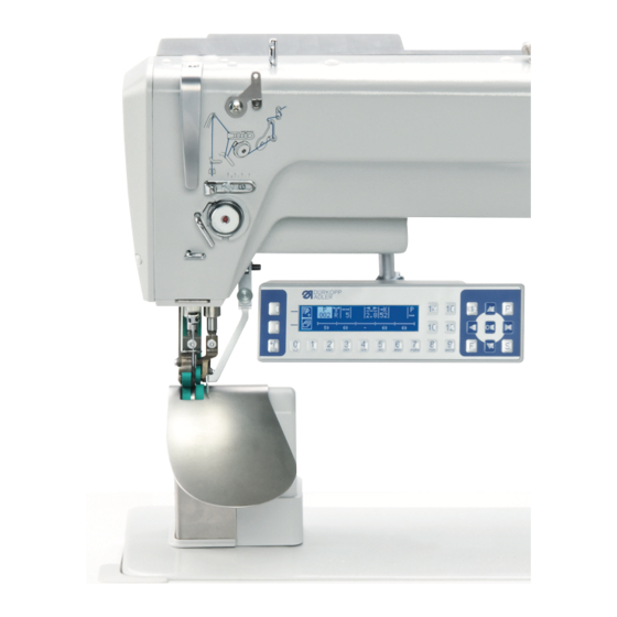
Machine Description 4 Machine Description Figure 1: General view of the 650 sewing machine (1) - Machine upper section (3) - Foot pedal (2) - Thread reel holder (4) - Main switch Operating Instructions 650-16 - 01.0 - 06/2014... - Page 26 Machine Description Operating Instructions 650-16 - 01.0 - 06/2014...
-
Page 27: Operation
Important: The unwinding bracket must be horizontal and be positioned above the thread reels. 2. Thread the needle thread as shown in the following figure. Figure 2: Threading the needle Operating Instructions 650-16 - 01.0 - 06/2014... -
Page 28: Setting The Needle Thread Tension
Figure 4: Interlacing Correct thread interlacing in the middle of the material being sewn Needle thread tension too weak or hook thread tension too strong Needle thread tension too strong hook thread tension too weak Operating Instructions 650-16 - 01.0 - 06/2014... -
Page 29: Setting The Thread Regulator
When the largest thread quantity is required then the thread tension spring (3) must be pulled approx. 0.5 mm down from its upper end position. This occurs when the needle thread loop matches the maximum hook diameter. Operating Instructions 650-16 - 01.0 - 06/2014... -
Page 30: Winding The Hook Thread
Moving the bobbin without performing sewing can cause dam- age to the presser foot and the bobbin case in the hook. Activate bobbin mode if you wish to wind the hook thread with- out performing sewing. Operating Instructions 650-16 - 01.0 - 06/2014... - Page 31 6. Start sewing. 7. Once the bobbin is full, the winder switches off automatically ( Service manual section 16.1). 8. Pull off the bobbin, clamp the thread under the cutter (3) and tear it off. Operating Instructions 650-16 - 01.0 - 06/2014...
-
Page 32: Replacing The Hook Thread Bobbin
2. Move the needle to the up position. 3. Lift the bobbin housing flap (1). 4. Remove the bobbin housing upper section (7) with the bobbin (3). 5. Remove the empty bobbin (3) from the bobbin housing upper section (7). Operating Instructions 650-16 - 01.0 - 06/2014... - Page 33 (7). 4. The bobbin must rotate in the direction of the arrow when pull- ing out the thread. 5. Insert the bobbin housing (7) again. 6. Push the hook cover (2) upwards. Operating Instructions 650-16 - 01.0 - 06/2014...
-
Page 34: Setting The Hook Thread Tension
When the bobbin housing contains a full bobbin it must sink slowly under its own weight. Figure 9: Bobbin housing sinking The braking spring prevents the bobbin running on when the thread has been cut. Operating Instructions 650-16 - 01.0 - 06/2014... - Page 35 8. Remove the hook thread in the direction of sewing at an angle of 45°. About half the tension value should be evident. 9. Then tighten the adjusting screw (3) up to the recommended tension value. Operating Instructions 650-16 - 01.0 - 06/2014...
-
Page 36: Changing The Needle
An incorrect hook distance can cause the following malfunctions: • Changing to a thinner needle: Missing stitches Thread damage • Changing to a thicker needle: Damage to the hook tip Damage to the needle Operating Instructions 650-16 - 01.0 - 06/2014... -
Page 37: Raising The Presser Feet
(2) - Additional pedal (optional) Steps 1. Push the pedal halfway backwards. 2. Raise the presser feet. 1. Push the pedal fully backwards. 2. Activate the thread cut-off and raise the presser feet. Operating Instructions 650-16 - 01.0 - 06/2014... -
Page 38: Functions Of The Optional Additional Pedal
Figure 13: Knee switch (1) - Knee switch Steps 1. Depress the knee switch. The next step is called up. Operating Instructions 650-16 - 01.0 - 06/2014... -
Page 39: Sewing
• Release the pedal. The presser feet are lowered. Altering the fullness • Press the fullness button or the left pedal. The selected fullness value is activated. At the end of the seam Operating Instructions 650-16 - 01.0 - 06/2014... -
Page 40: Customer Service
Contact for repairs if machine is damaged: Dürkopp Adler AG Potsdamer Str. 190 33719 Bielefeld, Germany Tel. +49 (0) 180 5 383 756 Fax +49 (0) 521 925 2594 E-mail: service@duerkopp-adler.com Internet: www.duerkopp-adler.com Operating Instructions 650-16 - 01.0 - 06/2014... -
Page 41: Installation
Wear safety gloves and safety shoes when unpacking and installing. 6.1 Scope of delivery The scope of delivery depends on your specific order. Check that all parts required are present before installing the machine. Figure 14: Scope of delivery Operating Instructions 650-16 - 01.0 - 06/2014... -
Page 42: Removing The Transport Locks
• Lashing straps and wooden blocks from the upper part of the machine, the table and the support frame • Restrain block and lashing straps from the sewing head Operating Instructions 650-16 - 01.0 - 06/2014... -
Page 43: Assembling The Frame
6. Screw the cable duct (6) (30 x 30 x 250 mm) for the setpoint transducer cables on to the frame brace (5). 7. Turn the adjusting screw (8) to ensure that the frame stands securely. The frame must stand with all four feet on the floor. Operating Instructions 650-16 - 01.0 - 06/2014... -
Page 44: Pre-Assembling The Table Top
(chipboard screws 3.5 x 17). 11. Fit the electric cables, 6.9 Electrical connection, page 47. Larger scale diagrams can be found at the end of the manual, 10 Appendix, page 127. Operating Instructions 650-16 - 01.0 - 06/2014... -
Page 45: Attaching The Table Top And Pedals To The Frame
9. Insert the thread reel holder (1) into the hole in the table top, and secure it with a nut and washer. 10. Fit and align the thread reel holders and unwinding bracket. Operating Instructions 650-16 - 01.0 - 06/2014... -
Page 46: Completing The Table Top
3. Using 4.5 x 15 (4x) screws, screw on the hinge mountings (3). 4. Using 4.5 x 55 (8x) screws, screw the edge strips (4) to the table top. 5. Insert the upper part support (2). Operating Instructions 650-16 - 01.0 - 06/2014... -
Page 47: Setting The Working Height
1. Slacken the screws (1) on the frame bars. 2. Set the table top to the desired working height. 3. To avoid jamming, slide the table top in or out evenly at both sides. 4. Tighten the screws (1). Operating Instructions 650-16 - 01.0 - 06/2014... -
Page 48: Inserting The Machine Upper Part
If the machine is supplied ready assembled, the transport eye is included in the accessories pack. WARNING Risk of injury due to the upper part tipping When transporting the machine, secure the upper part against tipping. Operating Instructions 650-16 - 01.0 - 06/2014... -
Page 49: Electrical Connection
The voltage on the type plate of the sewing drive must correspond to the mains voltage. DANGER Danger of life-threatening electric shock Make sure that the voltage listed on the type plate of the sewing drive corresponds to the mains supply voltage. Operating Instructions 650-16 - 01.0 - 06/2014... -
Page 50: Connecting The Mains Power Supply
7. Connect the LED transformer leads to “L1” and “L2” (in addition to the mains supply cable). 8. Connect the protective earth conductors of the control cabinet and the additional controller to the main switch. Operating Instructions 650-16 - 01.0 - 06/2014... -
Page 51: Connecting The Cables To The Upper Part
(3) - Bridge plug 9850 001208 (2) - Connections, side 2 All cables are color coded. Important: The bridge plug 9850 001208 (3) must be plugged into the controller, otherwise the controller will not work. Operating Instructions 650-16 - 01.0 - 06/2014... -
Page 52: Connecting The Cables For The Additional Controller
6.9.3 Connecting the cables to the upper part, page 49. 2. Lay the cable (1) for the stepper motor in the underside of the casing (2) and plug it into the connection plug. Operating Instructions 650-16 - 01.0 - 06/2014... -
Page 53: Connecting The Setpoint Transducers To The Controller
Figure 24: Connecting the setpoint transducers to the controller Steps 1. Connect the setpoint transducer for the main pedal to the “Speed” plug (1) (X120b). 2. Connect the setpoint transducer for the additional pedal to the “Fullness” plug (2) (X120t). Operating Instructions 650-16 - 01.0 - 06/2014... -
Page 54: Connecting The Equipotential Bonding For The Upper Part
(2) - Protective earth conductor Steps 1. Screw the protective earth conductor (2) to the upper part (1), lay it to the additional control cabinet and plug it on the flat plug (3). Operating Instructions 650-16 - 01.0 - 06/2014... -
Page 55: Connecting The Equipotential Bonding For The Controller
1. Screw the protective earth conductor (3) of the plug (2) on to the control cabinet (1). 2. Screw the protective earth conductor (4) (150 mm long) on to the frame (5) using a toothed shakeproof washer. Operating Instructions 650-16 - 01.0 - 06/2014... -
Page 56: Connecting The Equipotential Bonding For The Additional Controller
1. Plug the protective earth conductor (1) into the flat plug (2) on the additional control cabinet. 2. Lay the cable (2) (300 mm long) to the control cabinet (3) and screw it on. Operating Instructions 650-16 - 01.0 - 06/2014... -
Page 57: Connecting The Equipotential Bonding For The Sewing Head Motor
The protective earth conductor (2) for the sewing head motor is connected in the plug (3) for sewing head drive. Steps 1. Screw the protective earth conductor (2) to the earthing point on the control cabinet (1). Operating Instructions 650-16 - 01.0 - 06/2014... -
Page 58: Connecting The Equipotential Bonding For The Knee Switch
1. Screw the protective earth conductor (3) (650 mm long) to the attachment clip (1) on the knee switch. 2. Lay the cable in the cable duct (2) and plug the additional con- troller on to the flat plug (4). Operating Instructions 650-16 - 01.0 - 06/2014... -
Page 59: Connecting The Equipotential Bonding For The Setpoint Transducers
2. Lay the cable (4) through the cable duct (3) to the setpoint transducer (2) and screw it on (optional). 3. Screw the protective earth conductor (1) (650 mm long) on to the setpoint transducer (2) and to the control cabinet (6). Operating Instructions 650-16 - 01.0 - 06/2014... -
Page 60: Connecting The Knee Switch
(1) - Plug (3) - Knee switch (2) - Cable Steps 1. Lay the cable (2) for the knee switch (3) through the cable duct to the controller and connect it to the plug (1). Operating Instructions 650-16 - 01.0 - 06/2014... -
Page 61: Connecting The Control Panel
2. Plug the plug for the cable (1) on to the control panel, through the opening in the table top (2) to the control cabinet, and con- nect it to the socket (X170 Panel). Operating Instructions 650-16 - 01.0 - 06/2014... -
Page 62: Connecting The Led Sewing Light
2. Connect the supply cable for the sewing light controller within the main switch, 6.9.2 Connecting the mains power supply, page 48. 3. Connect the plug (3) for the LED light to the black plug of the sewing light controller output cable. Operating Instructions 650-16 - 01.0 - 06/2014... -
Page 63: Connect The Additional Sewing Light (Waldmann) (Optional)
12. If the requirements are not satisfied: Alter the thread tension, page 26 and page 32. If necessary, also check the settings listed in the service manual and correct them as required. Operating Instructions 650-16 - 01.0 - 06/2014... - Page 64 Installation Operating Instructions 650-16 - 01.0 - 06/2014...
-
Page 65: Controller With The Op3000 Control Panel
Controller with the OP3000 control panel 7 Controller with the OP3000 control panel 7.1 OP3000 control panel Figure 34: Control unit panel All settings in the controller for the 650-16 are performed using the OP3000 control panel. Function 0 to 16... -
Page 66: Switching The Sewing Machine On
• On the right of the screen the controller software version The machine performs a reference run: The display shows the program last used, or manual mode. Figure 36: Display of the program last used Figure 37: Display in manual mode Operating Instructions 650-16 - 01.0 - 06/2014... -
Page 67: Controller Operating Modes
Quick programming allows very quick and simple creation of new sewing programs. • Programming mode Programming mode allows new sewing programs to be cre- ated, edited, deleted, copied, and mirrored (left sleeve / right sleeve). Operating Instructions 650-16 - 01.0 - 06/2014... -
Page 68: Manual Mode
• Use the second pedal to select the fullness, if fitted. Stitch length Value range: 1.0 to 5.5 mm • Use to select the “Stitch length” parameter. • Use to change the stitch length Operating Instructions 650-16 - 01.0 - 06/2014... - Page 69 Measurement restarts when sewing starts again. Creating a program 7.8.1 Creating a program, page 82 Switch between upper and lower fullness ESC, F and S No function assigned 0 – 16 Fullness values No function assigned Operating Instructions 650-16 - 01.0 - 06/2014...
-
Page 70: Quick Access Function (Softkey Menu)
If sewing is stopped within the seam, the needle is positioned up or down. Automatic step progression on/off (available only in Automatic mode) • Press the key “4”. Automatic step progression is enabled/disabled whilst sewing a seam. Operating Instructions 650-16 - 01.0 - 06/2014... -
Page 71: Menu For Other Settings
Value range: 1 – 15 Start Tack (bartack at the start of a seam) Value range: on/off End Tack (bartack at the end of a seam) Value range: on/off Thread Trim (thread cutoff) Value range: on/off Operating Instructions 650-16 - 01.0 - 06/2014... -
Page 72: Sewing Process
1. Move the pedal to the “0” position. 2. Change the desired parameter on the control panel. 3. Push the pedal forwards again and sew. The seam will be sewn using the altered parameter value. Operating Instructions 650-16 - 01.0 - 06/2014... -
Page 73: Automatic Mode
• Input the program number using the 0 - 9 keys ” and confirm with “OK as required. If you select program 000, the controller selects Manual mode Operating Instructions 650-16 - 01.0 - 06/2014... - Page 74 • Click on the “OK” button to confirm. • Press or “ESC” to exit the menu. Program bar Length per step in mm, or a dash (-) if no automatic step progression Operating Instructions 650-16 - 01.0 - 06/2014...
-
Page 75: Sewing Process
The program bar (1) shows the progress of the seam. The number under the current step shows the outstanding length of the step. The program bar shows half the current step in bold. Figure 42: Current step Operating Instructions 650-16 - 01.0 - 06/2014... -
Page 76: Canceling The Program
The program remains stopped at the cutoff point. Lower softkey Softkey menu 7.4 Manual mode, page 66 7.5.3 Canceling the program 1. Cut off (push the pedal fully back). 2. Press the “ESC” key. Operating Instructions 650-16 - 01.0 - 06/2014... -
Page 77: Quick Programming
or the keypad keys 0 – 9 to select a program number. 4. Press the “OK” key. The following information is shown on the display, the “P” in the program number field flashes: Operating Instructions 650-16 - 01.0 - 06/2014... - Page 78 • Use the “+/-” key to select upper (+) or lower (-) full- ness. Stitch length for the current step Value range: 1.0 to 5.5 mm • Use to select the “Stitch length” parameter. • Use to change the stitch length. Operating Instructions 650-16 - 01.0 - 06/2014...
-
Page 79: Creating A Program By Keyboard Input
• The teach-in for the 2nd sleeve side is opened • The selection screen for the action of creating the 2nd sleeve side is opened The machine switches to Automatic mode. The program that was just created is selected. Operating Instructions 650-16 - 01.0 - 06/2014... -
Page 80: Creating A Program By Sewing The Seam
85. Once all steps are complete: 5. Press the “S” key. The program is saved. The following display appears: Figure 48: Display after creating a program by sewing the seam Operating Instructions 650-16 - 01.0 - 06/2014... -
Page 81: Edit Mode
The selected step is shown bold in the program bar. 2. Use to select the parameter to the changed for the respective step, and use to change it. Operating Instructions 650-16 - 01.0 - 06/2014... -
Page 82: Changing Further Parameters For The Current Step
to change its value and press “OK” to confirm it. Symbol Meaning Step. Len. (step length) Auto Forward (automatic step progression) Alternate (sewing foot alternation) Foot Press (presser foot pressure) 5. Exit the submenu using “ESC” or Operating Instructions 650-16 - 01.0 - 06/2014... -
Page 83: Changing Further Parameters For The Selected Program
Fulln. Corr. (fullness correction) Start Tack (bartack at the start of a seam) End Tack (bartack at the end of a seam) Thread Trim (thread cutoff) 5. Exit the submenu using “ESC” or Operating Instructions 650-16 - 01.0 - 06/2014... -
Page 84: Programming Mode
The following display appears, with “P” flashing: Figure 53: Display after specifying the program number 4. If necessary change the sleeve side or other parameters, 7.7 Edit mode, page 79. 5. Press the key. Operating Instructions 650-16 - 01.0 - 06/2014... - Page 85 • the sleeve side that was programmed should be mirrored • the sleeve side that was programmed should not be mir- rored • the teach-in for the 2nd sleeve side should be opened. Operating Instructions 650-16 - 01.0 - 06/2014...
-
Page 86: Copying The Program
Figure 58: Display after specifying the program number 4. Load the desired changes into the new program. 5. Press the “ESC” key. The controller exits Programming mode and reverts to Auto- matic mode. Operating Instructions 650-16 - 01.0 - 06/2014... -
Page 87: Deleting A Program
1. Press the key. The softkey menu appears. Figure 60: Softkey menu 2. Press the key. 3. Press the “ESC” key. The controller exits Programming mode and reverts to Automatic mode. Operating Instructions 650-16 - 01.0 - 06/2014... - Page 88 Controller with the OP3000 control panel Operating Instructions 650-16 - 01.0 - 06/2014...
-
Page 89: Controller With The Op7000 Control Panel
The seam programs are displayed continuously whilst sewing is in progress. Programs can be mirrored for the other side of the sewing material. Operating Instructions 650-16 - 01.0 - 06/2014... -
Page 90: Switching The Sewing Machine On
• Programming mode In Programming mode, new seam programs can be created (PROGRAMMING), existing seam programs can be edited, deleted, copied and mirrored (EDIT) and also optimized (Length Correction). Operating Instructions 650-16 - 01.0 - 06/2014... -
Page 91: General Operation
Numeric values for the individual parameters and text for the program names can be input in the individual operating modes. The inputs are performed using separate user interfaces. 8.4.1 Inputting numeric values Figure 62: Inputting numeric values Operating Instructions 650-16 - 01.0 - 06/2014... - Page 92 Changing the value incrementally up or down Delete the input value Exit the user interface without inputting or saving any values Save the value that was input and exist the user interface Operating Instructions 650-16 - 01.0 - 06/2014...
-
Page 93: Entering Text
• Symbol for a new seam program • Symbol for exiting the user interface Input line for the text Keypad Meaning of the buttons Symbols/buttons Meaning Input of numbers in the text Input of text Operating Instructions 650-16 - 01.0 - 06/2014... - Page 94 Exit the user interface without inputting or saving any text Input of a space Switching between upper case/lower case Delete letters/digits from the input line Save the value that was input and exist the user interface Operating Instructions 650-16 - 01.0 - 06/2014...
-
Page 95: Manual Mode Man
The symbols for all the parameters that can be set are displayed here. The gray fields above the parameter symbols show the respective current values. Right pane (4) Another user interface or another operating mode can be selected here. Operating Instructions 650-16 - 01.0 - 06/2014... -
Page 96: Parameters That Can Be Set In Man Mode
Inputting the stitch length in mm 1. Press the desired button. The user interface for setting the parameter is displayed. For some parameters the setting is more than just a numerical value. These parameters are described below. Operating Instructions 650-16 - 01.0 - 06/2014... - Page 97 2. If a higher or lower degree of fullness is required, use the arrow keys to display more buttons. 3. Input the fullness using the buttons 0 to 16. Operating Instructions 650-16 - 01.0 - 06/2014...
- Page 98 1. Input the curve support using the buttons 1 to 6. MAN mode Other program parameters After the Other program parameters button has been pressed, an overview of all the available parameters is displayed. Figure 65: Other program parameters in MAN mode Operating Instructions 650-16 - 01.0 - 06/2014...
-
Page 99: Sewing Process
1. Move the pedal to the 0 position. 2. Change the desired parameter on the control panel ( page 94). 3. Push the pedal forwards and sew. The seam will be sewn using the altered parameter value. Operating Instructions 650-16 - 01.0 - 06/2014... -
Page 100: Automatic Mode Auto
The gray fields above the parameter symbols show the respective current values. Right pane (4) Another user interface or another operating mode can be selected here. Operating Instructions 650-16 - 01.0 - 06/2014... -
Page 101: Auto Parameters That Can Be Set
1. Press the desired button. The user interface for setting the desired parameter is dis- played. For some parameters the setting is more than just a numerical value. These extended parameters are described in detail below. Operating Instructions 650-16 - 01.0 - 06/2014... - Page 102 AUTO. 3. Press the Abort button to cancel the selection of the program. If necessary the seam program selected is discarded and the user interface for the Automatic mode AUTO is displayed. Operating Instructions 650-16 - 01.0 - 06/2014...
- Page 103 • The sizes highlighted in red represent the reference sizes for the graduation logic. 1. Press on the desired sewing material size. The user interface for the Automatic mode AUTO is dis- played. Operating Instructions 650-16 - 01.0 - 06/2014...
- Page 104 Display of further buttons for inputting the fullness. The buttons 0 to 16 are available for input. 1. Select the type of fullness. The type of fullness selected is displayed in an activated control field within the symbol. Operating Instructions 650-16 - 01.0 - 06/2014...
- Page 105 The correction value is saved and the previous user interface is displayed. If the correction value is changed in AUTO Automatic mode it remains active until the controller changes to the next pro- gram. Operating Instructions 650-16 - 01.0 - 06/2014...
- Page 106 After the Other program parameters button has been pressed, an overview of all the available parameters is displayed. Figure 71: Other program parameters in AUTO mode Parameters Meaning Foot Pressure Presser foot pressure Value range: 1 ... 10 Operating Instructions 650-16 - 01.0 - 06/2014...
-
Page 107: Sewing Process
The sewing progress is displayed graphically in the left pane as a red bar. Figure 72: Sewn sewing steps and sewing step in progress The remaining sewing length per sewing step is displayed. Operating Instructions 650-16 - 01.0 - 06/2014... - Page 108 2. Change the fullness correction using the buttons + F% or - F%. 3. Push the pedal forwards and sew. The changed fullness value is applied and displayed. Cancel the seam program 1. Push the pedal fully back. The seam program is canceled. Operating Instructions 650-16 - 01.0 - 06/2014...
-
Page 109: Programming Mode
Right pane (4) Here new seam programs can be created page 113, existing seam programs can be deleted page 121, copied page 121 and optimized page 122 (Length Correction). Operating Instructions 650-16 - 01.0 - 06/2014... -
Page 110: Editing Existing Programs (Edit)
Set the stitch length in mm in the current sewing step Switch the seam length measurement in the current sewing step on or off Other sewing step parameters in EDIT programming mode, page 112 Operating Instructions 650-16 - 01.0 - 06/2014... - Page 111 • The sizes highlighted in red represent the reference sizes for the graduation logic. 1. Press on the desired sewing material size. The EDIT user interface of the programming mode is dis- played. Operating Instructions 650-16 - 01.0 - 06/2014...
- Page 112 Display of further buttons for inputting the fullness. The buttons 0 to 16 are available for input. 1. Select the type of fullness. The type of fullness selected is displayed in an activated control field within the symbol. Operating Instructions 650-16 - 01.0 - 06/2014...
- Page 113 Backtack at start of the seam on/off Value range: 0, 1 Backtack at End Backtack at end of the seam on/off Value range: 0, 1 Thread Trim Thread cutoff on/off Value range: 0, 1 Operating Instructions 650-16 - 01.0 - 06/2014...
- Page 114 Presser foot alternation whilst the needle is in the seam. Value range: 0 ... 2.5 mm Foot Pressure Presser foot pressure. Value range: 1 ... 10 Maximum Speed Sewing speed/rotational speed. Value range: 100 ... 4000 Operating Instructions 650-16 - 01.0 - 06/2014...
-
Page 115: Creating A New Program (Programming)
5. Select the next sewing step, either by pressing on the number of the first sewing steps or by using the knee switch. The second sewing step is displayed with its number in the left pane. Operating Instructions 650-16 - 01.0 - 06/2014... - Page 116 All sewing steps were input manually and continue with step 9 ended with END. 8. If the threads were not cut off after sewing, a message appears. Cut off the threads. The message is cleared. Operating Instructions 650-16 - 01.0 - 06/2014...
- Page 117 Mirror programmed side to other side AUTO mode Program other side PROGRAMMING-mode Finish AUTO mode Pressing the Abort button closes the window, the AUTO user interface is then displayed. All the data that were input are deleted by this! Operating Instructions 650-16 - 01.0 - 06/2014...
- Page 118 Set the stitch length in mm in the current sewing step Switch the seam length measurement in the current sewing step on or off Other sewing step parameters in programming mode PROGRAMMING, page 120 Operating Instructions 650-16 - 01.0 - 06/2014...
- Page 119 • The currently selected size is indicated by a double arrow (>>). 1. Select the size system in the right pane. 2. Press on the desired sewing material size. The PROGRAMMING user interface of the programming mode is displayed. Operating Instructions 650-16 - 01.0 - 06/2014...
- Page 120 Display of further buttons for inputting the fullness. The buttons 0 to 16 are available for input. 1. Select the type of fullness. The type of fullness selected is displayed in an activated control field within the symbol. Operating Instructions 650-16 - 01.0 - 06/2014...
- Page 121 Backtack at End Backtack at end of the seam on/off Value range: 0, 1 Thread Trim Thread cutoff on/off Value range: 0, 1 Grading Factor Grading factor Value range: 0.0 ... 6.0 (% per size) Operating Instructions 650-16 - 01.0 - 06/2014...
- Page 122 Figure 84: Other sewing step parameters Parameters Meaning Foot Stroke Alternation Presser foot alternation whilst the needle is in the seam Value range: 0 ... 2.5 mm Foot Pressure Presser foot pressure Value range: 1 ... 10 Operating Instructions 650-16 - 01.0 - 06/2014...
-
Page 123: Copying The Seam Program
A message is displayed asking whether you really wish to delete the active seam program. 3. To delete the program, confirm by pressing the Yes button. The seam program is deleted. An appropriate message is displayed. Operating Instructions 650-16 - 01.0 - 06/2014... -
Page 124: Length Correction (Length Correction)
Figure 85: Length correction interface 2. Sew the sewing step. 3. Switch to the next sewing step either manually at the control panel or using the knee switch. The sewing progress is displayed graphically. Operating Instructions 650-16 - 01.0 - 06/2014... -
Page 125: Service Mode Service
Service mode contains functions for use during service work. Service mode is password-protected, to avoid accidentally chang- ing the machine settings. More information on the contents of Service mode can be found in the Service manual 650. Operating Instructions 650-16 - 01.0 - 06/2014... - Page 126 Controller with the OP7000 control panel Operating Instructions 650-16 - 01.0 - 06/2014...
-
Page 127: Disposal
When disposing of the machine, be aware that it consists of a range of different materials (steel, plastic, electronic components, etc.). Observe the applicable national regulations for disposal. Operating Instructions 650-16 - 01.0 - 06/2014... - Page 128 Disposal Operating Instructions 650-16 - 01.0 - 06/2014...
-
Page 129: Appendix
Appendix 10Appendix Dimensions for manufacturing a table top Operating Instructions 650-16 - 01.0 - 06/2014... - Page 130 Appendix Operating Instructions 650-16 - 01.0 - 06/2014...
- Page 131 Appendix Operating Instructions 650-16 - 01.0 - 06/2014...
- Page 132 Appendix Operating Instructions 650-16 - 01.0 - 06/2014...
- Page 134 DÜRKOPP ADLER AG Potsdamer Straße 190 33719 Bielefeld GERMANY Phone +49 (0) 521 / 925-00 E-mail service@duerkopp-adler.com www.duerkopp-adler.com...
Need help?
Do you have a question about the 650-16 and is the answer not in the manual?
Questions and answers