Vega VEGABAR 54 Operating Instructions Manual
Pressure transmitter
Hide thumbs
Also See for VEGABAR 54:
- Operating instructions manual (80 pages) ,
- Product information (28 pages) ,
- Operating instructions manual (72 pages)
Table of Contents
Advertisement
Quick Links
Advertisement
Table of Contents

Subscribe to Our Youtube Channel
Related Manuals for Vega VEGABAR 54


Summary of Contents for Vega VEGABAR 54
-
Page 1: Operating Instructions
Operating Instructions VEGABAR 54 4 … 20 mA/HART... -
Page 2: Table Of Contents
6 Setup with the indicating and adjustment module PLICSCOM Short description ..... . . VEGABAR 54 - 4 … 20 mA/HART... - Page 3 11.3 Certificates ......11.4 Industrial property rights....VEGABAR 54 - 4 … 20 mA/HART...
- Page 4 Contents Supplementary operating instructions manuals Information: VEGABAR 54 is available in different versions and is supplied order-specifically. Depending on the selected version, sup- plementary operating instructions manuals come with the shipment. The supplementary operating instructions are stated in paragraph "Product description".
-
Page 5: About This Document
1 About this document 1.1 Function This operating instructions manual has all the information you need for quick setup and safe operation of VEGABAR 54. Please read this manual before you start setup. 1.2 Target group This operating instructions manual is directed to trained personnel. -
Page 6: For Your Safety
- Emission EN 61326: 2004 (class B) Susceptibility EN 61326: 2004 incl. supplement A LVD: EN 61010-1: 2001 VEGABAR 54 is not subject to the pressure device guideline. Due to the flush diaphragm, no own pressure compartment is formed. VEGABAR 54 - 4 … 20 mA/HART... -
Page 7: Compatibility Acc. To Namur Ne 53
The range of available functions depends on the respective software version of the individual components. The software version of VEGABAR 54 can be determined as follows: via PACTware™ on the type label of the electronics via the adjustment module PLICSCOM On our website www.vega.com you will find all software... -
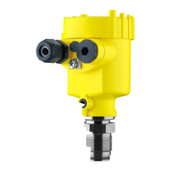
Page 8: Product Description
Housing cover, optionally available with indicating and adjustment module PLICSCOM The components are available in different versions. Fig. 1: Example of a VEGABAR 54 with process fitting G1A and plastic housing Housing cover with integrated PLICSCOM (optional) Housing with electronics Process fitting with measuring cell... -
Page 9: Adjustment
The exact range is stated in the "Technical data" in the "Supplement". 3.3 Adjustment VEGABAR 54 can be adjusted with four different adjustment media: the indicating and adjustment module PLICSCOM with the suitable VEGA DTM in conjunction with an adjustment software acc. - Page 10 Product description Storage and transport temperature see "Supplement – Storage and transport tem- perature Technical data – Ambient conditions" Relative humidity 20 … 85 % VEGABAR 54 - 4 … 20 mA/HART...
-
Page 11: Mounting
Use the recommended cable (see chapter "Connecting to Moisture power supply") and tighten the cable gland. You can give your VEGABAR 54 additional protection against moisture penetration by leading the connection cable down- ward in front of the cable entry. Rain and condensation water can thus drain off. - Page 12 Applying tightening force to the housing can damage its internal mechanical components. Warning: The VEGABAR 54 with thread G½A is only sealed on the hexagon. The front of the process fitting must not be used for sealing! Tightening, e.g. in a welded socket for manometer connection can damage the process fitting.
-
Page 13: Mounting Steps, Remote Housing - Non-Ex
A torque > 5 Nm can damage the wall mounting plate. 4.4 Mounting steps, remote housing - Ex VEGABAR 54 with remote housing for wall mounting is Wall mounting supplied with a mounting socket. VEGABAR 54 - 4 … 20 mA/HART... - Page 14 ") 62mm (2 ") 85mm (3 ") Fig. 4: VEGABAR 54 for wall mounting, bottom view of mounting plate. Drill dimension VEGABAR 54 for mounting on carrier rail is supplied with a Carrier rail mounting mounting adapter. Fig. 5: VEGABAR 54 for carrier rail mounting...
-
Page 15: Connecting To Power Supply
"Technical data" in the "Supplement". Provide a reliable separation between the supply circuit and the mains circuits acc. to DIN VDE 0106 part 101. The VEGA power supply units VEGATRENN 149AEx, VEGASTAB 690, VEGADIS 371 as well as all VEGAMETs meet this require- ment. -
Page 16: Connection Procedure
(see following illustration) 7 Insert the wire ends into the open terminals according to the wiring plan 8 Press down the opening levers of the terminals, you will hear the terminal spring closing VEGABAR 54 - 4 … 20 mA/HART... - Page 17 Proceed as follows: IP 68 version with remote housing - Non-Ex 1 Loosen the four screws on the housing socket with an Allen key size 4 2 Remove the mounting plate from the housing socket VEGABAR 54 - 4 … 20 mA/HART...
- Page 18 5 cm of the cable mantle, strip approx. 1 cm insulation from the ends of the individual wires. After shortening the cable, fasten the type plate with sup- port back onto the cable. VEGABAR 54 - 4 … 20 mA/HART...
- Page 19 5 cm of the cable mantle, strip approx. 1 cm insulation from the ends of the individual wires. After shortening the cable, fasten the type plate with sup- port back onto the cable. VEGABAR 54 - 4 … 20 mA/HART...
-
Page 20: Wiring Plans, Single Chamber Housing
The electrical connection of the sensor to the remote housing is finished. 5.3 Wiring plans, single chamber housing The following illustrations apply to the non-Ex as well as to the Ex ia version. VEGABAR 54 - 4 … 20 mA/HART... - Page 21 Fig. 11: Electronics and connection compartment, single chamber housing Plug connector for VEGACONNECT (I²C interface) Spring-loaded terminals for connection of the external indication VEGADIS Ground terminal for connection of the cable screen Spring-loaded terminals for power supply VEGABAR 54 - 4 … 20 mA/HART...
-
Page 22: Wiring Plans, Double Chamber Housing
Housing cover, electronics compartment Filter element for pressure compensation or blind stopper with version IP 66/ IP 68, 1 bar Cable entry or plug Version IP 66/IP 68, 1 bar not with four-wire instruments VEGABAR 54 - 4 … 20 mA/HART... - Page 23 Terminals for VEGADIS 61 Connection compartment I 2 C Fig. 15: Connection compartment, double chamber housing Plug connector for VEGACONNECT (I²C interface) Ground terminal for connection of the cable screen Spring-loaded terminals for power supply VEGABAR 54 - 4 … 20 mA/HART...
-
Page 24: Wiring Plans, Double Chamber Housing Exd
Housing cover, electronics compartment Filter element for pressure compensation or blind stopper with version IP 66/ IP 68, 1 bar Cable entry or plug Version IP 66/IP 68, 1 bar not with four-wire instruments VEGABAR 54 - 4 … 20 mA/HART... - Page 25 Internal connection cable to the connection compartment Terminals for VEGADIS 61 Connection compartment Fig. 19: Connection compartment, double chamber housing Exd Spring-loaded terminals for power supply and cable screen Ground terminal for connection of the cable screen VEGABAR 54 - 4 … 20 mA/HART...
-
Page 26: Wiring Plans, Version Ip 66/Ip 68 (1 Bar)
This version is only available for instruments with absolute pressure measuring ranges. Wire assignment, connection cable Fig. 21: Wire assignment, connection cable br (+) and bl (–) for power supply or to the processing system Screen VEGABAR 54 - 4 … 20 mA/HART... -
Page 27: Wiring Plans, Remote Housing With Ip 68 Version - Non-Ex
Connecting to power supply 5.7 Wiring plans, remote housing with IP 68 version - Non-Ex Overview Fig. 22: VEGABAR 54 in IP 68 version 25 bar non-Ex and axial cable outlet, remote housing VEGABAR 54 - 4 … 20 mA/HART... - Page 28 Fig. 23: Electronics and connection compartment Plug connector for VEGACONNECT (I²C interface) Spring-loaded terminals for connection of the external indication VEGADIS Cable gland to VEGABAR Ground terminal for connection of the cable screen Spring-loaded terminals for power supply VEGABAR 54 - 4 … 20 mA/HART...
- Page 29 Fig. 24: Connection of the sensor in the housing socket Brown Blue Yellow White Screen Breather capillaries Wiring plan, remote elec- tronics Display I 2 C Fig. 25: Wiring plan, remote electronics Supply voltage VEGABAR 54 - 4 … 20 mA/HART...
-
Page 30: Wiring Plans, Remote Housing With Ip 68 Version - Ex
Connecting to power supply 5.8 Wiring plans, remote housing with IP 68 version - Ex Overview Fig. 26: VEGABAR 54 in IP 68 version Ex and axial cable outlet, remote housing Electronics and connection compartment I 2 C Fig. 27: Electronics and connection compartment Plug connector for VEGACONNECT (I²C interface) -
Page 31: Switch On Phase
I 2 C Fig. 29: Wiring plan, remote electronics Supply voltage 5.9 Switch on phase After VEGABAR 54 is connected to power supply, the Switch on phase instrument carries out a self-test for approx. 30 seconds. The following steps are carried out: Internal check of the electronics Indication of the instrument type, the firmware version as... -
Page 32: Setup With The Indicating And Adjustment Module Plicscom
4 Screw housing cover with inspection window tightly back Removal is carried out in reverse order. PLICSCOM is powered by the sensor, an additional con- nection is not necessary. VEGABAR 54 - 4 … 20 mA/HART... - Page 33 Setup with the indicating and adjustment module PLICSCOM Fig. 30: Installation of PLICSCOM Note: If you intend to retrofit VEGABAR 54 with a PLICSCOM for continuous measured value indication, a higher cover with an inspection glass is required. VEGABAR 54 - 4 … 20 mA/HART...
-
Page 34: Adjustment System
The functions of the individual keys are shown in the above illustration. Approx. 10 minutes after the last pressing of a key, an automatic reset to measured value indication is triggered. Any values not confirmed with [OK] will not be saved. VEGABAR 54 - 4 … 20 mA/HART... -
Page 35: Setup Procedure
PACTware™ or DTM. HART mode Standard Address 0 VEGABAR 54 can be used for process pressure as well as for Process pressure or level measurement level measurement. Default setting is process pressure measurement. The mode can be changed in the adjustment menu. - Page 36 The adjustment unit is now changed from bar to mbar. Proceed as follows: Carry out position correction 1 Edit the offset value in the menu item "Position correction" with [OK]. Selection options: mbar, bar, psi, Pa, kPa, MPa, inHg, mmHg, inH VEGABAR 54 - 4 … 20 mA/HART...
- Page 37 [OK]. Proceed as follows: Carry out span adjustment 1 Edit the mbar value in the menu item "span" with [OK]. Span adjustment 100.0 % +1000.0 mbar 0000.0 mbar VEGABAR 54 - 4 … 20 mA/HART...
- Page 38 [ESC] or the displayed limit value can be accepted with [OK]. The setup of VEGABAR 54 for process pressure measure- ment is finished. All other menu items are described in the separate operating instructions manual of the indicating and adjustment module PLICSCOM.
- Page 39 Also the current measured value is shown in the menu items for the min./max. adjustment. VEGABAR 54 is preset to application "Process pressure Select application "Level measurement" measurement". Proceed as follows when switching over to application "Level measurement":...
- Page 40 Density 0001.000 kg/dm³ 6 Enter the requested density value with [–>] and [+], confirm with [OK] and move to position correction with [–>]. The adjustment unit is now changed from bar to m. VEGABAR 54 - 4 … 20 mA/HART...
- Page 41 [ESC] or the displayed limit value can be accepted with [OK]. Proceed as follows: Carrying out max. adjustment 1 Edit the % value in the menu item "Max. adjustment" with [OK]. VEGABAR 54 - 4 … 20 mA/HART...
- Page 42 [ESC] or the displayed limit value can be accepted with [OK]. The setup of VEGABAR 54 is finished. All other menu items are described in the separate operating instructions manual of the indicating and adjustment module PLICSCOM.
-
Page 43: Menu Schematic
0 % = 0.0 l 100 % = 1000.0 l Diagnostics Basic adjustment Display ▶ Diagnostics Service Info Peak values Sensor status Trend recording Tmin: -12.5°C Tmax: +85.5°C p-min: -0.58 bar p-max: 16.765 bar VEGABAR 54 - 4 … 20 mA/HART... - Page 44 Diagnostics Service ▶ Info Sensor type Date of manufacture Date of last change using PC Sensor details VEGABAR 5x 26. Aug. 2005 Display now? Software version Serial number 3.22 26. Aug. 2005 12345678 VEGABAR 54 - 4 … 20 mA/HART...
-
Page 45: Saving The Parameter Adjustment Data
They are hence available for multiple use or service purposes. If VEGABAR 54 is equipped with an indicating and adjustment module PLICSCOM, the most important data can be read out of the sensor into PLICSCOM. The procedure is described in the operating instructions manual "Indicating and adjustment... -
Page 46: Setup With Pactware™ And Other Adjustment Programs
Fig. 32: PC connected directly to the sensor RS232 connection VEGABAR 54 I²C adapter cable for VEGACONNECT 3 Necessary components: VEGABAR 54 PC with PACTware™ and suitable VEGA-DTM VEGACONNECT 3 with I²C adapter cable (article no. 2.27323) Power supply unit VEGABAR 54 - 4 … 20 mA/HART... -
Page 47: Parameter Adjustment With Pactware
With power supply units with integrated HART resistor (inner resistor approx. 250 Ohm) there is no additional external resistor necessary. This applies e.g. for VEGA instruments VEGATRENN 149A, VEGADIS 371, VEGAMET 381. Also standard Ex separators are normally equipped with a sufficient current limitation resistor. -
Page 48: Parameter Adjustment With Ams™ And Pdm
Setup with PACTware™ and other adjustment programs Note: Keep in mind that for parameter adjustment of a VEGABAR 54, DTM Collection 04/2004 or a newer version is required. All currently available VEGA-DTMs are provided in the DTM Collection on CD and can be obtained from the responsible VEGA agency for a token fee. -
Page 49: Maintenance And Fault Rectification
Maintenance and fault rectification 8 Maintenance and fault rectification 8.1 Maintenance When used as directed in normal operation, VEGABAR 54 is completely maintenance-free. 8.2 Fault rectification VEGABAR 54 offers maximum reliability. Nevertheless faults Causes of malfunction can occur during operation. These may be caused by the following, e.g.:... - Page 50 E036 no operable sensor software à carry out a software update or return instrument for repair Fault message can come up if the pressure is higher than the nominal range VEGABAR 54 - 4 … 20 mA/HART...
-
Page 51: Exchanging The Electronics
The electronics without serial number includes no order-specific data. The serial number can be found on the type label of VEGABAR 54 or on the delivery note. In both cases, the function of VEGABAR 54 is ensured. - Page 52 Maintenance and fault rectification Attach the completed form and possibly also a safety data sheet to the instrument. Send the instrument to the respective address of your agency. In Germany to the VEGA headquarters in Schiltach. VEGABAR 54 - 4 … 20 mA/HART...
-
Page 53: Dismounting
Take note of chapters "Mounting" and "Connecting to power supply" and carry out the listed steps in reverse order. 9.2 Disposal VEGABAR 54 consists of materials which can be recycled by specialised recycling companies. We have purposely de- signed the electronic modules to be easily separable. Mark the instrument as scrap and dispose of it according to national government regulations (e.g. -
Page 54: Functional Safety Acc. To Iec 61508-4 (Sil)
= λ /(λ +λ Diagnostic Coverage; DC = λ /(λ +λ Failure In Time (1 FIT = 1 failure/10 MTBF Mean Time Between Failure MTTF Mean Time To Failure MTTR Mean Time To Repair VEGABAR 54 - 4 … 20 mA/HART... - Page 55 Only process-relevant parameters can be modified on the instrument (e.g. measuring range, current output in case of failure ...) The modification of these process-relevant parameters is protected (e.g. password, ...) The safety function requires less than SIL4 VEGABAR 54 - 4 … 20 mA/HART...
-
Page 56: Planning
If the measuring system delivers output currents of "fail low" or Configuration of the process- ing unit "fail high", this can be due to a failure. The processing unit must therefore interpret such currents as failure and output a suitable fault signal. VEGABAR 54 - 4 … 20 mA/HART... - Page 57 The lifetime of the components is around 8 to 12 years (IEC 61508-2, 7.4.7.4, remark 3) The processing unit can interpret "fail low" and "fail high" failures as interferences and output a suitable fault signal VEGABAR 54 - 4 … 20 mA/HART...
-
Page 58: Adjustment Instructions And Parameter Adjustment
Instrument parameters measuring system, the instrument parameters must be set according to the application. VEGABAR 54 suitable for the VEGA-DTM in conjunction with an adjustment software acc. to FDT/DTM standard, e.g. PACTware™ is permitted as auxiliary means. Via the adjustment software, the parameter "Sensor acc. to Create a measurement loop SIL"... -
Page 59: Set Up
An electronics exchange is easily possible and described in the operating instructions manual. VEGABAR 54 - 4 … 20 mA/HART... -
Page 60: Recurring Function Test
The failure rates of the electronics, the mechanical parts of the Failure rates pressure transmitter as well as the process fitting were determined by an FMEDA acc. to IEC 61508. Basis for the calculations are component failure rates acc. to SN 29500. All VEGABAR 54 - 4 … 20 mA/HART... - Page 61 MTBF = MTTF + MTTR 0.9x10 max. useful life of the measuring system for the safety approx. 10 years function The judgment of the modification service was part to ensure Proven in use "Proven in use". VEGABAR 54 - 4 … 20 mA/HART...
- Page 62 Time-dependent process of period up to 10 years virtually linear to the operating time. The above values only apply to the T interval, after which a Proof recurring function test must be carried out. VEGABAR 54 - 4 … 20 mA/HART...
- Page 63 (especially for the selected application). A Common Cause Factor must be taken into account. Numbers see in the above charts. VEGABAR 54 - 4 … 20 mA/HART...
-
Page 64: Supplement
PUR, FEP, PE transmitter and remote housing - Plug connector, remote housing Ex - Cover screw plug connector StSt - Type plate support with IP 68 ver- PE hard sion on cable - Transport cover VEGABAR 54 - 4 … 20 mA/HART... - Page 65 -10 … 110 % of the nominal measuring range - pressure value from -50 … 150 % of the nominal measuring range Recommended max. turn down 1:30 (no limitation) -120: Values less than -1.0 bar cannot be adjusted. VEGABAR 54 - 4 … 20 mA/HART...
- Page 66 0…5 bar/0…500 kPa 100 bar/10.000 kPa 0…10 bar/0…1.000 kPa 150 bar/15.000 kPa 0…25 bar/0…2500 kPa 200 bar/20000 kPa 0…60 bar/0…6000 kPa 200 bar/20000 kPa Limitation to 200 bar acc. to the pressure device directive. VEGABAR 54 - 4 … 20 mA/HART...
- Page 67 - with PLICSCOM -20 … +70°C (-4 … +158°F) Relating to the nominal range, incl. hysteresis and repeatability, determined acc. to the limit point method. Acc. to IEC 60770-1, relating to the nominal range. VEGABAR 54 - 4 … 20 mA/HART...
- Page 68 184°F cleaning temperature) - Kalrez 6375 -10 … +120°C (14 … +248°F) Vibration resistance Mechanical vibrations with 4 g and 5 … 100 Hz. Tested acc. to the regulations of German Lloyd, GL directive 2. VEGABAR 54 - 4 … 20 mA/HART...
- Page 69 Electromechanical data – version IP 66/IP 68, 1 bar Version IP 66/IP 68, 1 bar is only available for instruments with absolute pressure measuring ranges. Depending on the version M12x1, acc. to DIN 43650, Harting, Amphenol- Tuchel, 7/8" FF VEGABAR 54 - 4 … 20 mA/HART...
- Page 70 1x closing cap ½ NPT, 1x blind stopper ½ NPT 1x plug (depending on the version), 1x blind stopper M20x1.5 Option: Depending on the version M12x1, acc. to DIN 43650, Harting, Amphenol-Tuchel, 7/8" FF VEGABAR 54 - 4 … 20 mA/HART...
- Page 71 - EEx ia instrument 12 … 30 V DC - Exd instrument 18 … 36 V DC Permissible residual ripple - <100 Hz <1 V - 100 Hz … 10 kHz <10 mV Load see diagram VEGABAR 54 - 4 … 20 mA/HART...
- Page 72 This can falsify the meas- ured value. Only with instruments with absolute pressure ranges Deviating data with Ex applications: see separate safety instructions. Depending on order specification. VEGABAR 54 - 4 … 20 mA/HART...
-
Page 73: Dimensions
½ NPT Fig. 37: Housing versions in protection IP 66/IP 68, 1 bar (with integrated PLICSCOM the housing height increases by 9 mm/0.35 in) Stainless steel housing Aluminium double chamber housing Aluminium housing VEGABAR 54 - 4 … 20 mA/HART... - Page 74 ~ 66mm (2 ") Fig. 38: Transmitter and remote housing with IP 68 version IP 68 version - Ex ø 42 ø 40 Fig. 39: IP 68 version with cable outlet axial lateral VEGABAR 54 - 4 … 20 mA/HART...
- Page 75 Supplement Remote housing with IP 68 version - Ex ca. 69,5 ø 77 M20x1 M20x1,5 Fig. 40: Remote housing with IP 68 version VEGABAR 54 - 4 … 20 mA/HART...
- Page 76 ø 30mm ") ") ") ø 32mm ø 27mm ø 40mm ") ") ") Fig. 41: VEGABAR 54, threaded fitting: GA = G½A flush, GB = G¾A completely flush, GC = G1A completely flush VEGABAR 54 - 4 … 20 mA/HART...
- Page 77 Supplement VEGABAR 54, flange connection 4xø14 inch 4xø " " " " " " Fig. 42: VEGABAR 54, flange connection form B1, EN 1092-1 VEGABAR 54 - 4 … 20 mA/HART...
- Page 78 ") ") Fig. 43: VEGABAR 54, fitting for the paper industry: VP = G 1" PASVE, BF = M30x1.5, BS = M30x1.5 for headbox, PC = PMC 1", PD = PMC 1¼", PE = PMC 12" VEGABAR 54 - 4 … 20 mA/HART...
-
Page 79: Certificates
Supplement 11.3 Certificates CE declaration of conformity Fig. 44: CE declaration of conformity VEGABAR 54 - 4 … 20 mA/HART... - Page 80 Supplement Manufacturer declaration Fig. 45: Manufacturer declaration VEGABAR 54 - 4 … 20 mA/HART...
- Page 81 Supplement SIL declaration of conformity VEGABAR 54 - 4 … 20 mA/HART...
-
Page 82: Industrial Property Rights
Supplement 11.4 Industrial property rights VEGABAR 54 - 4 … 20 mA/HART... - Page 83 Supplement VEGABAR 54 - 4 … 20 mA/HART...
- Page 84 All statements concerning scope of delivery, application, practical use and operating conditions of the sensors and processing systems correspond to the information avail- able at the time of printing. © VEGA Grieshaber KG, Schiltach/Germany 2005 Technical data subject to alterations 29694-EN-051004...
Need help?
Do you have a question about the VEGABAR 54 and is the answer not in the manual?
Questions and answers