Vega VEGABAR 87 Operating Instructions Manual
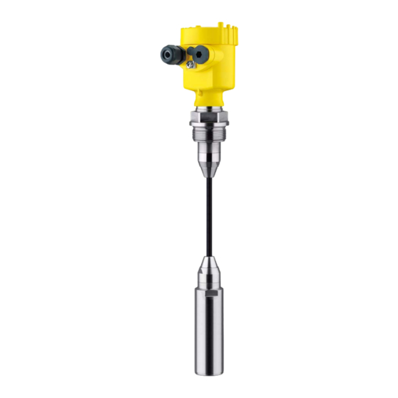
Submersible pressure transmitter with metal measuring cell
Hide thumbs
Also See for VEGABAR 87:
- Operating instructions manual (84 pages) ,
- Quick setup manual (24 pages) ,
- Operating instructions manual (76 pages)

Subscribe to Our Youtube Channel
Related Manuals for Vega VEGABAR 87


Summary of Contents for Vega VEGABAR 87
- Page 1 Operating Instructions Submersible pressure transmitter with metal measuring cell VEGABAR 87 4 … 20 mA Document ID: 45507...
-
Page 2: Table Of Contents
Connect the PC ......................42 Parameter adjustment with PACTware ................42 Saving the parameterisation data ................... 43 Set up with other systems ....................44 DD adjustment programs ....................44 Field Communicator 375, 475 ..................44 VEGABAR 87 • 4 … 20 mA... - Page 3 11.5 Industrial property rights ....................69 11.6 Trademark ........................69 Safety instructions for Ex areas Take note of the Ex specific safety instructions for Ex applications. These instructions are attached as documents to each instrument with Ex approval and are part of the operating instructions. Editing status: 2020-05-12 VEGABAR 87 • 4 … 20 mA...
-
Page 4: About This Document
Symbols used Document ID This symbol on the front page of this instruction refers to the Docu- ment ID. By entering the Document ID on www.vega.com you will reach the document download. Information, note, tip: This symbol indicates helpful additional infor- mation and tips for successful work. -
Page 5: For Your Safety
During work on and with the device, the required personal protective equipment must always be worn. Appropriate use Model VEGABAR 87 is a pressure transmitter for level and gauge measurement. You can find detailed information about the area of application in chapter "Product description". Operational reliability is ensured only if the instrument is properly used according to the specifications in the operating instructions manual as well as possible supplementary instructions. -
Page 6: Namur Recommendations
That is why we have introduced an environment management system with the goal of continuously improving company environmental pro- tection. The environment management system is certified according to DIN EN ISO 14001. Please help us fulfil this obligation by observing the environmental instructions in this manual: • Chapter "Packaging, transport and storage" • Chapter "Disposal" VEGABAR 87 • 4 … 20 mA... -
Page 7: Product Description
Fig. 1: Layout of the type label (example) Product code Field for approvals Technical data Serial number of the instrument QR code Symbol of the device protection class ID numbers, instrument documentation VEGABAR 87 • 4 … 20 mA... -
Page 8: Principle Of Operation
Alternatively, you can access the data via your smartphone: • Download the VEGA Tools app from the "Apple App Store" or the "Google Play Store" • Scan the DataMatrix code on the type label of the instrument or •... - Page 9 3 Product description Depending on the version, the VEGABAR 87 is also suitable for Electronic differential pressure electronic differential pressure measurement. For this, the instrument is combined with a slave sensor. Fig. 3: Electronic differential pressure measurement through Master/Slave combination You can find detailed information in the operating instructions of the respective slave sensor. The process pressure acts on the sensor element via the stainless Measuring system steel diaphragm and an internal transmission liquid.
-
Page 10: Packaging, Transport And Storage
Nonobservance of these instructions can cause damage to the device. Transport inspection The delivery must be checked for completeness and possible transit damage immediately at receipt. Ascertained transit damage or con- cealed defects must be appropriately dealt with. VEGABAR 87 • 4 … 20 mA... -
Page 11: Accessories
DIN 2501, EN 1092-1, BS 10, ASME B 16.5, JIS B 2210-1984, GOST 12821-80. Welded sockets and Welded sockets are used to connect the sensors to the process. adapters Threaded adapters enable simple adaptation of sensors with stand- ard threaded fittings, e.g. to process-side hygiene connections. VEGABAR 87 • 4 … 20 mA... -
Page 12: Mounting
To maintain the housing protection, make sure that the housing lid is closed during operation and locked, if necessary. Screwing in Devices with threaded fitting are screwed into the process fitting with a suitable wrench via the hexagon. See chapter "Dimensions" for wrench size. VEGABAR 87 • 4 … 20 mA... - Page 13 Make sure that the upper temperature limits stated in chapter "Technical data" for the environment of the electronics hous- ing and connection cable are not exceeded. Fig. 5: Temperature ranges Process temperature Ambient temperature VEGABAR 87 • 4 … 20 mA...
-
Page 14: Ventilation And Pressure Compensation
4 Mounting Depending on the transmitter, the VEGABAR 87 is supplied with a Transport and mounting protection protective cap or a transport and mounting protection. Fig. 6: VEGABAR 87, transport and mounting protection Transmitter Transport and mounting protection Remove this protection after mounting and before setting up the instrument. - Page 15 Instruments in protection IP66/IP68 (1 bar) - ventilation via capillar- ies in non-detachable cable • Instruments with absolute pressure → Filter element - Position Turn the metal ring in such a way that the filter element points Ex-d version downward after installation of the instrument. This provides better protection against buildup. VEGABAR 87 • 4 … 20 mA...
- Page 16 With relative pressure measuring ranges, the ambient pressure is detected and compensated by a reference sensor in the electronics. Fig. 9: Position of the filter element - gastight leadthrough Filter element Gas-tight leadthrough VEGABAR 87 • 4 … 20 mA...
-
Page 17: Level Measurement
Mount the instrument so that it is protected against pressure shocks from the stirrer External housing Configuration Fig. 11: Arrangement measurement loop, external housing Sensor Connection cable sensor, external housing External housing Signal cable VEGABAR 87 • 4 … 20 mA... -
Page 18: Connecting To Power Supply
In electroplating plants as well as plants for cathodic corrosion protec- tion it must be taken into account that significant potential differences exist. This can lead to unacceptably high currents in the cable screen if it is grounded at both ends. VEGABAR 87 • 4 … 20 mA... -
Page 19: Connecting
3. Loosen compression nut of the cable gland and remove blind plug 4. Remove approx. 10 cm (4 in) of the cable mantle, strip approx. 1 cm (0.4 in) of insulation from the ends of the individual wires VEGABAR 87 • 4 … 20 mA... -
Page 20: Single Chamber Housing
10. Reinsert the display and adjustment module, if one was installed 11. Screw the housing lid back on The electrical connection is finished. Single chamber housing The following illustration applies to the non-Ex, Ex-ia and Ex-d ver- sion. VEGABAR 87 • 4 … 20 mA... -
Page 21: Ex-D-Ia Double Chamber Housing
For display and adjustment module or interface adapter Internal connection to the plug connector for external display and adjust- ment unit (optional) Note: HART multidrop mode is not possible when using an Ex-d-ia instru- ment. VEGABAR 87 • 4 … 20 mA... -
Page 22: Housing Ip66/Ip68 (1 Bar)
Ground terminal for connection of the cable screening Housing IP66/IP68 (1 bar) Wire assignment, con- nection cable Fig. 16: Wire assignment in permanently connected connection cable Brown (+) and blue (-) to power supply or to the processing system Shielding VEGABAR 87 • 4 … 20 mA... -
Page 23: External Housing
Breather capillaries Electronics and connec- tion compartment for power supply 4...20mA 6 7 8 Fig. 18: Electronics and connection compartment Electronics module Cable gland for voltage supply Cable gland for connection cable, transmitter VEGABAR 87 • 4 … 20 mA... -
Page 24: Switch-On Phase
The output signal jumps to the set fault current Then the actual measured value is output to the signal cable. The value takes into account settings that have already been carried out, e.g. default setting. VEGABAR 87 • 4 … 20 mA... -
Page 25: Set Up With The Display And Adjustment Module
Fig. 20: Installing the display and adjustment module in the electronics compart- ment of the single chamber housing Note: If you intend to retrofit the instrument with a display and adjustment module for continuous measured value indication, a higher lid with an inspection glass is required. VEGABAR 87 • 4 … 20 mA... -
Page 26: Adjustment System
The pen oper- ates the four keys of the display and adjustment module right through the closed lid (with inspection window) of the sensor housing. VEGABAR 87 • 4 … 20 mA... -
Page 27: Measured Value Indication
With the "OK" key you move (during the initial setup of the instrument) to the selection menu "Language". Selection language In this menu item, you can select the national language for further parameterization. VEGABAR 87 • 4 … 20 mA... -
Page 28: Parameter Adjustment - Quick Setup
Setup: Settings, e.g., for measurement loop name, application, units, position correction, adjustment, signal output Display: Settings, e.g., for language, measured value display, lighting Diagnosis: Information, e.g. on instrument status, pointer, measure- ment reliability, simulation VEGABAR 87 • 4 … 20 mA... - Page 29 In this menu item you activate/deactivate the slave sensor for elec- tronic differential pressure and select the application. VEGABAR 87 can be used for process pressure and level measure- ment. The setting in the delivery status is process pressure measure- ment. The mode can be changed in this adjustment menu.
- Page 30 20 % of the nominal measuring range, then no position correction is possible. Adjustment VEGABAR 87 always measures pressure independently of the pro- cess variable selected in the menu item "Application". To output the selected process variable correctly, an allocation of the output signal to 0 % and 100 % must be carried out (adjustment).
- Page 31 1. Select the menu item "Setup" with [->] and confirm with [OK]. Now select with [->] the menu item "Zero adjustment" and confirm with [OK]. 2. Edit the mbar value with [OK] and set the cursor to the requested position with [->]. VEGABAR 87 • 4 … 20 mA...
- Page 32 [OK]. The span adjustment is finished. Min. adjustment level Proceed as follows: 1. Select the menu item "Setup" with [->] and confirm with [OK]. Now select with [->] the menu item "Adjustment", then "Min. adjustment" and confirm with [OK]. VEGABAR 87 • 4 … 20 mA...
- Page 33 - and the indication or output of the volume is required. Corresponding linearization curves are preprogrammed for these vessels. They represent the correlation between the level per- centage and vessel volume. The linearization applies to the measured value indication and the current output. VEGABAR 87 • 4 … 20 mA...
- Page 34 In the menu item "Lock/unlock adjustment" you safeguard the sensor parameters against unauthorized or unintentional modifications. With active PIN, only the following adjustment functions are possible without entering a PIN: The device assumes an approximately constant temperature and static pressure and converts the differential pressure into the flow rate via the characteristic curve extracted by root. VEGABAR 87 • 4 … 20 mA...
- Page 35 Polish • Czech • Turkish In delivery status, the VEGABAR 87 is set to English. Display value 1 and 2 In this menu item, you define which measured value is displayed. The setting in the delivery status for the display value is "Lin. percent". Display format 1 and 2 In this menu item you define the number of decimal positions with which the measured value is displayed.
- Page 36 In this menu item you can simulate measured values. This allows the Simulation signal path to be tested, e.g. through downstream indicating instru- ments or the input card of the control system. VEGABAR 87 • 4 … 20 mA...
- Page 37 Setup Menu item Parameter Default value Measurement loop name Sensor Application Application Level Units Unit of measurement mbar (with nominal measuring range ≤ 400 mbar) bar (with nominal measuring ranges ≥ 1 bar) Temperature unit °C Position correction 0.00 bar VEGABAR 87 • 4 … 20 mA...
- Page 38 Actual measured value Temperature Actual temperature values from measuring cell, elec- tronics Simulation Process pressure Additional adjustments Menu item Parameter Default value 0000 Date/Time Actual date/Actual time Copy instrument settings Special parameters No reset VEGABAR 87 • 4 … 20 mA...
- Page 39 Scaling (2) In menu item "Scaling (2)" you define the scaling format on the display and the scaling of the measured level value for 0 % and 100 %. VEGABAR 87 • 4 … 20 mA...
- Page 40 Device name In this menu item, you can read out the instrument name and the instrument serial number: Instrument version In this menu item, the hardware and software version of the sensor is displayed. VEGABAR 87 • 4 … 20 mA...
-
Page 41: Saving The Parameterisation Data
If the instrument is equipped with a display and adjustment module, In the display and adjust- ment module the parameter adjustment data can be saved therein. The procedure is described in menu item "Copy device settings". VEGABAR 87 • 4 … 20 mA... -
Page 42: Setup With Pactware
Further setup steps are described in the operating instructions manu- al "DTM Collection/PACTware" attached to each DTM Collection and which can also be downloaded from the Internet. Detailed descrip- tions are available in the online help of PACTware and the DTMs. VEGABAR 87 • 4 … 20 mA... -
Page 43: Saving The Parameterisation Data
The standard version is available as a download under www.vega.com/downloads and "Software". The full version is avail- able on CD from the agency serving you. Saving the parameterisation data We recommend documenting or saving the parameterisation data via PACTware. -
Page 44: Set Up With Other Systems
This software is updated via the Internet and new EDDs are automatically accepted into the device catalogue of this software after they are released by the manufacturer. They can then be transferred to a Field Communicator. VEGABAR 87 • 4 … 20 mA... -
Page 45: Diagnostics And Servicing
General software error F105 The instrument is still in the start phase, Wait for the end of the switch-on phase the measured value could not yet be Measured value is deter- determined mined VEGABAR 87 • 4 … 20 mA... - Page 46 Impermissible pressure value If necessary, use an instrument with a higher measuring range Tab. 7: Error codes and text messages, information on causes as well as corrective measures VEGABAR 87 • 4 … 20 mA...
-
Page 47: Rectify Faults
Reaction after fault recti- Depending on the reason for the fault and the measures taken, the fication steps described in chapter "Setup" must be carried out again or must be checked for plausibility and completeness. VEGABAR 87 • 4 … 20 mA... -
Page 48: Exchange Process Module On Version Ip68 (25 Bar)
Proceed as follows when carrying out the exchange: 1. Losen the fixing screw with the hexagon key wrench 2. Carefully detach the cable assembly from the process module Fig. 26: VEGABAR 87 in IP68 version, 25 bar and lateral cable outlet, external housing Process module Plug connector... -
Page 49: Exchanging The Electronics Module
By doing this you help us carry out the repair quickly and without having to call back for needed information. In case of repair, proceed as follows: VEGABAR 87 • 4 … 20 mA... - Page 50 • Attach the completed form and, if need be, also a safety data sheet outside on the packaging • Ask the agency serving you to get the address for the return ship- ment. You can find the agency on our homepage. VEGABAR 87 • 4 … 20 mA...
-
Page 51: Dismount
Pass the instrument directly on to a specialised recycling company and do not use the municipal collecting points. If you have no way to dispose of the old instrument properly, please contact us concerning return and disposal. VEGABAR 87 • 4 … 20 mA... -
Page 52: Supplement
Externes Gehäuse - abweichende Werkstoffe Ʋ Gehäuse und Sockel Kunststoff PBT (Polyester), 316L Ʋ Sockeldichtung EPDM Ʋ Dichtung unter Wandmontageplatte EPDM Ʋ Sichtfenster Gehäusedeckel Polycarbonat (UL746-C gelistet) Erdungsklemme 316Ti/316L Glas bei Aluminium- und Edelstahl Feingussgehäuse Nur bei 316L mit 3A-Zulassung VEGABAR 87 • 4 … 20 mA... - Page 53 0 … 2.5 bar/0 … 250 kPa 25 bar/+2500 kPa 0 bar abs. 0 … 10 bar/0 … 1000 kPa 25 bar/+2500 kPa 0 bar abs. Zwischen Messwertaufnehmer und externem Elektronikgehäuse. Data on overload capability apply for reference temperature. VEGABAR 87 • 4 … 20 mA...
- Page 54 Switch-on phase Start-up time with operating voltage U Ʋ ≥ 12 V DC ≤ 9 s Ʋ < 12 V DC ≤ 22 s Staring current (for run-up time) ≤ 3.6 mA Output variable Output signal 4 … 20 mA - passive VEGABAR 87 • 4 … 20 mA...
- Page 55 : jump response time Process variable Output signal Dead time ≤ 50 ms Rise time ≤ 150 ms Step response time ≤ 200 ms (ti: 0 s, 10 … 90 %) Damping (63 % of the input variable) 0 … 999 s, adjustable via menu item "Damping" VEGABAR 87 • 4 … 20 mA...
- Page 56 4 … 20 mA and refers to the set span. Turn down (TD) is the ratio "nominal measuring range/set span". The thermal change of the zero signal and output span corresponds to the value F in chapter "Calculation of the total deviation (according to DIN 16086)". VEGABAR 87 • 4 … 20 mA...
- Page 57 < 0.05 %/10 K, max. < 0.15 %, each with -40 … +80 °C (-40 … +176 °F) The thermal change of the current output corresponds to the value F in chapter "Calculation of the total deviation (according to DIN 16086)". VEGABAR 87 • 4 … 20 mA...
- Page 58 -20 … +60 °C (-4 … +140 °F) -20 … +60 °C (-4 … +140 °F) schlusskabel PE Process conditions Process temperature Process temperature Ʋ Suspension cable -12 … +100 °C (+10 … +212 °F) VEGABAR 87 • 4 … 20 mA...
- Page 59 PE, PUR Ʋ Colour Black, blue Depending on the instrument version. 2 g with housing version stainless steel double chamber. IP66/IP68 (0.2 bar), only with absolute pressure. Breather capillaries not with Ex-d version. VEGABAR 87 • 4 … 20 mA...
- Page 60 Ʋ Example - with U = 24 V DC (24 V - 9.6 V)/0.022 A = 655 Ω Potential connections and electrical separating measures in the instrument Electronics Not non-floating Reference voltage 500 V AC Galvanic separation between electronics and metal housing parts VEGABAR 87 • 4 … 20 mA...
-
Page 61: Calculation Of The Total Deviation
+ (F + (F perf To provide a better overview, the formula symbols are listed together below: • : Total deviation • total : Basic deviation perf • : Long-term stability stab When used with fulfilled housing protection. VEGABAR 87 • 4 … 20 mA... -
Page 62: Praxisbeispiel
TD 20 : 1 Faktor FTD 1,75 10,5 Tab. 21: Ermittlung des Zusatzfaktors Turn Down für das Beispiel oben: F = 1,75 TBasis = 0,15 % x 1 x 1,75 = 0,26 % VEGABAR 87 • 4 … 20 mA... - Page 63 = (0,05 % x TD) stab = (0,05 % x 2,5) stab = 0,13 % stab = 0,32 % + 0,13 % = 0,45 % total Die Gesamtabweichung der Messeinrichtung beträgt somit 0,45 %. VEGABAR 87 • 4 … 20 mA...
-
Page 64: Dimensions
Der thermische Änderung des Stromausganges ist in diesem Beispiel vernachlässigbar klein. 11.4 Dimensions The following dimensional drawings represent only an extract of the possible versions. Detailed dimensional drawings can be downloaded at www.vega.com under "Downloads" and "Drawings". Housing ~ 116 mm... - Page 65 8 mm (0.12") (0.32") 110 mm x 90 mm (4.33" x 3.54") Fig. 32: VEGABAR 87, IP68 version with external housing Lateral cable outlet Axial cable outlet Plastic single chamber Stainless steel single chamber Seal 2 mm (0.079 in), (only with 3A approval)
- Page 66 1½ NPT 1½ NPT ø 8 mm (0.32") ø 29 mm (1.14") ø 40 mm (1.58") Fig. 33: VEGABAR 87, standard fittings Straining clamp Threaded fitting Thread G1½ Thread 1½ NPT Lock fitting VEGABAR 87 • 4 … 20 mA...
- Page 67 0.12 " 3" 0.75 " 4" 10" 1 .25" 7.87 " 8xø0.63 " 6.19 " 0.12 " Fig. 34: VEGABAR 87, flange connection Flanges according to DIN 2501 Flanges according to ASME B16.5 VEGABAR 87 • 4 … 20 mA...
- Page 68 ø 92 mm (3.62") ø 8 mm (0.32") ø 40 mm (1.58") Fig. 35: VEGABAR 87, hygienic fittings Clamp 2" PN 16 (ø 64 mm) DIN 32676, ISO 2852 Slotted nut DN 50 VEGABAR 87 • 4 … 20 mA...
-
Page 69: Industrial Property Rights
Les lignes de produits VEGA sont globalement protégées par des droits de propriété intellec- tuelle. Pour plus d'informations, on pourra se référer au site www.vega.com. VEGA lineas de productos están protegidas por los derechos en el campo de la propiedad indus- trial. Para mayor información revise la pagina web www.vega.com. - Page 70 Error codes 45, 46, 47 Fault – Rectification 47 Fault rectification 47 Functional principle 9 Grounding 18 Level measurement 17 Linearisation 33 Maintenance 45 Measurement setup – In the open vessel 17 Parameterization example 30 Peak value indicator 36 VEGABAR 87 • 4 … 20 mA...
- Page 71 Notes VEGABAR 87 • 4 … 20 mA...
- Page 72 Subject to change without prior notice © VEGA Grieshaber KG, Schiltach/Germany 2020 VEGA Grieshaber KG Phone +49 7836 50-0 Am Hohenstein 113...
Need help?
Do you have a question about the VEGABAR 87 and is the answer not in the manual?
Questions and answers