Vega VEGABAR 54 Operating Instructions Manual
Foundation fieldbus
Hide thumbs
Also See for VEGABAR 54:
- Operating instructions manual (84 pages) ,
- Product information (28 pages) ,
- Product information (32 pages)
Table of Contents
Advertisement
Quick Links
Advertisement
Table of Contents

Subscribe to Our Youtube Channel
Related Manuals for Vega VEGABAR 54


Summary of Contents for Vega VEGABAR 54
- Page 1 Operating Instructions VEGABAR 54 Foundation Fieldbus...
-
Page 2: Table Of Contents
Setup procedure ..... . . Menu schematic ..... . . VEGABAR 54 - Foundation Fieldbus... - Page 3 10.4 Industrial property rights....10.5 Trademark ......VEGABAR 54 - Foundation Fieldbus...
- Page 4 Contents Supplementary operating instructions manuals Information: VEGABAR 54 is available in many versions and is thus supplied according to customer order. Depending on the selected version, supplementary operating instructions man- uals also come with the delivery. You will find the supple- mentary operating instructions manuals in chapter "Product...
-
Page 5: About This Document
This symbol indicates special instructions for Ex applications. List The dot set in front indicates a list with no implied sequence. à Action This arrow indicates a single action. Sequence Numbers set in front indicate successive steps in a procedure. VEGABAR 54 - Foundation Fieldbus... -
Page 6: For Your Safety
- Emission EN 61326: 2004 (class B) Susceptibility EN 61326: 2004 including supplement A LVD: EN 61010-1: 2001 VEGABAR 54 is not subject to the pressure device guideline. Due to the flush diaphragm, no own pressure compartment is formed. VEGABAR 54 - Foundation Fieldbus... -
Page 7: Fulfilling Namur Recommendations
NAMUR recommendation NE 53 in respect to compat- ibility. VEGA instruments are generally upward and downward compatible: Sensor software to DTM VEGABAR 54 HART, PA or FF DTM VEGABAR 54 for adjustment software PACTware™ Indicating and adjustment module for sensor software The parameter adjustment of the basic sensor functions is independent of the software version. -
Page 8: Functional Range Of Approved Instruments
For approval-technical reasons, some functions for these instru- ments will be only available at a later date. You will find corresponding instructions in the description of the individual functions in this operating instructions manual. VEGABAR 54 - Foundation Fieldbus... -
Page 9: Environmental Instructions
The environment man- agement system is certified according to DIN EN ISO 14001. Please help us fulfil this obligation by observing the environ- mental instructions in this manual: Chapter "Storage and transport" Chapter "Disposal" VEGABAR 54 - Foundation Fieldbus... -
Page 10: Product Description
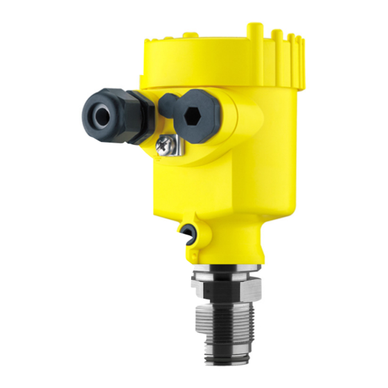
Housing cover, optionally available with indicating and adjustment module The components are available in different versions. Fig. 1: Example of a VEGABAR 54 with process fitting G1 A and plastic housing Housing cover with integrated PLICSCOM (optional) Housing with electronics Process fitting with measuring cell... -
Page 11: Principle Of Operation
Product description 3.2 Principle of operation VEGABAR 54 is a pressure transmitter for use in the paper, Area of application food processing and pharmaceutical industries as well as in water/sewage water plants. Depending on the version, it is used for level, gauge, absolute pressure or vacuum meas- urement. -
Page 12: Operation
VEGA DTM in conjunction with an adjustment software according to the FDT/DTM standard, e.g. PACTware™ and PC a configuration tool The entered parameters are generally saved in VEGABAR 54, optionally also in the indicating and adjustment module or in PACTware™. 3.4 Storage and transport Your instrument was protected by packaging during transport. -
Page 13: Mounting
Fig. 2: Measures against moisture penetration 4.2 Mounting steps For mounting VEGABAR 54, a welded socket is required. You Welding the socket find the components in the line of the VEGA accessory in the VEGABAR 54 - Foundation Fieldbus... -
Page 14: Mounting Steps, Remote Housing
Sealing/Screwing in threaded versions material on the process fitting thread 1½ NPT. à Screw VEGABAR 54 into the welded socket. Tighten the hexagon screw on the process fitting. Wrench size, see chapter "Dimensions". Warning: The housing must not be used to screw the instrument in! Applying tightening force on the housing can damage its rotational mechanical parts. - Page 15 The socket housing can be displaced by 180° to the wall mounting plate. Warning: The four screws for the socket housing must only be hand- screwed. A torque >5 Nm can damage the wall mounting plate. VEGABAR 54 - Foundation Fieldbus...
-
Page 16: Connecting To Voltage Supply
VEGABAR 54 requires a supply voltage of 9 … 32 V DC. Select power supply Power and the digital bus signal are carried on the same two- wire connection cable. -
Page 17: Connection Procedure
9 Check the hold of the wires in the terminals by lightly pulling on them 10 Connect the screen to the internal ground terminal and the external ground terminal to potential equalisation VEGABAR 54 - Foundation Fieldbus... - Page 18 Fig. 4: Connection steps 6 and 7 Proceed as follows: IP 68 version with remote housing 1 Loosen the four screws on the housing socket with an Allen key size 4 2 Remove the mounting plate from the housing socket VEGABAR 54 - Foundation Fieldbus...
- Page 19 Remove approx. 5 cm of the cable mantle, strip approx. 1 cm insulation from the ends of the individual wires. After shortening the cable, fasten the type plate with sup- port back onto the cable. VEGABAR 54 - Foundation Fieldbus...
-
Page 20: Wiring Plan, Single Chamber Housing
Plug connector for VEGACONNECT (I²C interface) Spring-loaded terminals for connection of the external indication VEGADIS Ground terminal for connection of the cable screen Spring-loaded terminals for Foundation Fieldbus connection Simulation switch ("on" = mode for simulation release) VEGABAR 54 - Foundation Fieldbus... -
Page 21: Wiring Plan, Double Chamber Housing
Blind stopper or plug M12x1 for VEGADIS 61 (option) Housing cover, electronics compartment Filter element for pressure compensation or blind stopper with version IP 66/ IP 68, 1 bar Cable entry or plug Version IP 66/IP 68, 1 bar not with four-wire instruments VEGABAR 54 - Foundation Fieldbus... - Page 22 Internal connection cable to the connection compartment Connection compartment I 2 C Fig. 11: Connection compartment, double chamber housing Plug connector for VEGACONNECT (I²C interface) Ground terminal for connection of the cable screen Spring-loaded terminals for voltage supply VEGABAR 54 - Foundation Fieldbus...
-
Page 23: Wiring Plan, Version Ip 66/Ip 68, 1 Bar
This version is only available for instruments with absolute pressure measuring ranges. Wire assignment, connection cable Fig. 13: Wire assignment, connection cable brown (+) and blue (-) to power supply or to the processing system Screen VEGABAR 54 - Foundation Fieldbus... -
Page 24: Wiring Plan, Remote Housing With Version Ip
Connecting to voltage supply 5.6 Wiring plan, remote housing with version IP 68 Overview Fig. 14: VEGABAR 54 in IP 68 version 25 bar, non-Ex and axial cable outlet, remote housing VEGABAR 54 - Foundation Fieldbus... - Page 25 Spring-loaded terminals for connection of the external indication VEGADIS Cable gland to VEGABAR Ground terminal for connection of the cable screen Spring-loaded terminals for Foundation Fieldbus connection Simulation switch ("on" = mode for simulation release) VEGABAR 54 - Foundation Fieldbus...
- Page 26 1 2 3 4 Fig. 16: Connection of the sensor in the housing socket Brown Blue Yellow White Screen Breather capillaries Wiring plan, remote elec- tronics Display I 2 C Fig. 17: Wiring plan, remote electronics Voltage supply VEGABAR 54 - Foundation Fieldbus...
-
Page 27: Switch-On Phase
Connecting to voltage supply 5.7 Switch-on phase After VEGABAR 54 is connected to voltage supply or after Switch-on phase voltage recurrence, the instrument carries out a self-check for approx. 30 seconds. The following steps are carried out: Internal check of the electronics Indication of the instrument type, the firmware as well as... -
Page 28: Setup With The Indicating And Adjustment Module Plicscom
(you can choose any one of four different positions - each displaced by 90°) 3 Press the indicating and adjustment module onto the electronics and turn it to the right until it snaps in. VEGABAR 54 - Foundation Fieldbus... - Page 29 Fig. 18: Installation of the indicating and adjustment module Note: If you intend to retrofit VEGABAR 54 with an indicating and adjustment module for continuous measured value indication, a higher cover with an inspection glass is required.
-
Page 30: Adjustment System
The functions of the individual keys are shown in the above illustration. Approx. 10 minutes after the last pressing of a key, an automatic reset to measured value indication is triggered. Any values not confirmed with [OK] will not be saved. VEGABAR 54 - Foundation Fieldbus... -
Page 31: Setup Procedure
Setup with the indicating and adjustment module PLICSCOM 6.4 Setup procedure VEGABAR 54 can be used for level as well as for process Level or process pressure measurement pressure measurement. Default setting is level measurement. The mode can be changed in the adjustment menu. - Page 32 4 Confirm with [OK], the submenu "Density unit" appears. Unit of measurement Density unit ▶ kg/dm³ 5 Select the requested unit, e.g. kg/dm³ with [->] and confirm with [OK], the submenu "Density" appears. Unit of measurement Density 0001000 kg/dm³ VEGABAR 54 - Foundation Fieldbus...
- Page 33 2 Set the requested % value with [+] and [->]. 3 Edit the requested mbar value with [OK]. 4 Set the requested mbar value with [+] and [->]. 5 Confirm with [+] and move to max. adjustment with [->]. The min. adjustment is finished. VEGABAR 54 - Foundation Fieldbus...
- Page 34 "Outside parameter limits" is displayed. The editing procedure can be aborted with [ESC] or the displayed limit value can be accepted with [OK]. Process pressure measurement Set up VEGABAR 54 in the following sequence: Parameter adjust- ment "Process pres- 1 Select application "Process pressure measurement"...
- Page 35 The actual measured value is displayed in addition to the menu items for zero/span adjustment. VEGABAR 54 is preset to application "Level measurement". Select application "Process pressure measurement" Proceed as follows when switching over to application "Process pressure measurement":...
- Page 36 2 Select with [->], e.g. to accept actual measured value. Position correction Accept current measured value? ▶ Accept Edit 3 Confirm with [OK] and move to min. (zero) adjustment with [->]. Selection options: mbar, bar, psi, Pa, kPa, MPa, inHg, mmHg, inH VEGABAR 54 - Foundation Fieldbus...
- Page 37 Information: The displayed pressure for 100 % corresponds to the nominal measuring range of the sensor (in the above example 1 bar = 1000 mbar). 2 Set the requested mbar value with [->] and [OK]. VEGABAR 54 - Foundation Fieldbus...
- Page 38 If the "Reset" is carried out, the sensor resets the values of the following functions to the reset values (see chart): Function Reset value Zero/Min. adjustment 0 mbar Span/Max. adjustment mbar/bar value corresponding to the nominal measuring range Sensor-specific basic adjustment. VEGABAR 54 - Foundation Fieldbus...
- Page 39 You will find a detailed description of these menu items in the operating instructions manual "Indicating and adjustment module". Special parameters are parameters which are set customer-specifically on the service level with the adjustment software PACTware™. VEGABAR 54 - Foundation Fieldbus...
-
Page 40: Menu Schematic
Diagnostics Service Info Displayed value Lighting ▼ AI-Out Switched off Diagnostics Basic adjustment Display ▶ Diagnostics Service Info Pointer Sensor status Trend recording Tmin.: -12.5 °C Tmax.: +85.5 °C p-min.: -0.58 bar p-max.: 16.765 bar VEGABAR 54 - Foundation Fieldbus... - Page 41 Basic adjustment Display Diagnostics Service ▶ Info Device-ID Sensor type Date of manufacture Last change using PC VEGABAR 5x 16. March 2006 Sensor-TAG Software version Serial number 3.32.00 16. March 2006 12345678 Sensor characteristics Display now? VEGABAR 54 - Foundation Fieldbus...
-
Page 42: Saving The Parameter Adjustment Data
If it is necessary to exchange VEGABAR 54, the indicating and adjustment module is inserted into the replacement instrument and the data are written into the sensor under the menu item "Copy sensor data". -
Page 43: Setup With Pactware™ And Other Adjustment Programs
A detailed description is available in the online help of PACTware™ and the VEGA DTMs. Note: Keep in mind that for setup of VEGABAR 54, DTM-Collection 10/2005 or a newer version must be used. VEGABAR 54 - Foundation Fieldbus... -
Page 44: Parameter Adjustment With Ams
All currently available VEGA DTMs are provided in the DTM Collection on CD and can be obtained from the responsible VEGA agency for a token fee. This CD includes also the up-to- date PACTware™ version. The basic version of this DTM Collection incl. -
Page 45: Maintenance And Fault Rectification
Maintenance and fault rectification 8 Maintenance and fault rectification 8.1 Maintenance When used as directed in normal operation, VEGABAR 54 is completely maintenance free. 8.2 Rectify faults VEGABAR 54 offers maximum reliability. Nevertheless faults Causes of malfunction can occur during operation. These may be caused by the following, e.g.:... - Page 46 Hardware error, electronics defective à Exchange instrument or return instrument for repair E113 Communication conflict à Exchange instrument or return instrument for repair Fault message can also appear if the pressure is higher than the nominal range VEGABAR 54 - Foundation Fieldbus...
-
Page 47: Exchange Of The Electronics Module
The electronics module without serial number contains no order- specific data. The serial number is stated on the type label of VEGABAR 54 or on the delivery note. 8.4 Instrument repair... -
Page 48: Dismounting
Correct disposal avoids negative effects to persons and environment and ensures recycling of useful raw materials. Materials: see "Technical data" If you cannot dispose of the instrument properly, please contact us about disposal methods or return. VEGABAR 54 - Foundation Fieldbus... -
Page 49: Supplement
- G1 A, M30x1.5; G1" PASVE 50 Nm Additional output parameter - temperature Processing is made via HART multidrop, Profibus PA and Foundation Fieldbus Range -50 … +150 °C (-58 … +302 °F) Resolution 1 °C (1.8 °F) VEGABAR 54 - Foundation Fieldbus... - Page 50 10:1 (no limitation) Nominal measuring ranges and overload resistance Nominal range Overload, max. pres- Overload, min. pressure sure Values less than -1 bar cannot be set. Limited to 200 bar according to the pressure device directive. VEGABAR 54 - Foundation Fieldbus...
- Page 51 0 … 5 bar/0 … 500 kPa 100 bar/10000 kPa 0 … 10 bar/0 … 1000 kPa 150 bar/15000 kPa 0 … 25 bar/0 … 2500 kPa 200 bar/20000 kPa 0 … 60 bar/0 … 6000 kPa 200 bar/20000 kPa VEGABAR 54 - Foundation Fieldbus...
- Page 52 - Turn down 1:1 <0.05 %/10 K - Turn down 1:1 up to 5:1 <0.1 %/10 K - Turn down up to 10:1 <0.15 %/10 K Outside the compensated temperature range: Incl. non-linearity, hysteresis and non-repeatability. VEGABAR 54 - Foundation Fieldbus...
- Page 53 The specifications of the pressure stage are used as an overview. The specifications on the type plate are applicable. Pressure stage, process fitting - Thread 316L PN 60 - Thread 316L 1" for PASVE PN 40 - PMC 316L PN 10 - Flange 316L PN 40 VEGABAR 54 - Foundation Fieldbus...
- Page 54 2x blind stopper M20x1.5; plug M12x1 for VEGADIS 61 (optional) Spring-loaded terminals for wire cross-section up to 2.5 mm² Tested according to EN 60068-2-27. Depending on the version M12x1, according to DIN 43650, Harting, Am- phenol-Tuchel, 7/8" FF. VEGABAR 54 - Foundation Fieldbus...
- Page 55 - Min. bending radius at 25 °C/77 °F 25 mm (0.985 in) - Diameter approx. 8 mm (0.315 in) - Colour - standard PE black - Colour - standard PUR Blue - Colour - Ex-version Blue VEGABAR 54 - Foundation Fieldbus...
- Page 56 - unassembled IP 20 - mounted into the sensor without IP 40 cover Materials - Housing - Inspection window Polyester foil Depending on the version M12x1, according to DIN 43650, Harting, Am- phenol-Tuchel, 7/8" FF. VEGABAR 54 - Foundation Fieldbus...
- Page 57 Instruments with gauge pressure measuring ranges cannot detect the am- bient pressure when submerged, e.g. in water. This can lead to falsification of the measured value. Deviating data in Ex applications: see separate safety instructions. Depending on order specification. VEGABAR 54 - Foundation Fieldbus...
-
Page 58: Information On Foundation Fieldbus
Channel = 2: Secondary Value 1 Channel = 3: Secondary Value 2 AI 3 Channel = 4: Temperature Fig. 21: Transducer Block VEGABAR 54 TB Transducer Block Function Block (AI =Analogue Input) Diagram, adjustment The following illustration shows the function of the adjustment:... - Page 59 Sensor_value scale_in_0 scale_in_100 -0,500 0,500 Fig. 22: Adjustment VEGABAR 54 Parameter list The following list contains the most important parameters and their meaning: primary_value Process Value after min/max-adjustment and linearization. Selected as input to AIFB by setting 'Channel' = 1. Unit derives from 'Primary_value_unit'...
- Page 60 "0: ""Uninitialized"" 1: ""Good"" 2: ""Not monotonous increasing"" 3: ""Not monotonous decreasing"" 4: ""Not enough values transmitted"" 5: ""Too many values transmitted"" 6: ""Gradient of edge too high"" 7: ""Values not excepted"" 8: ""Table currently loaded"" 9: ""Sorting and checking table""" SUB_DEVICE_NUMBER SENSOR_ELEMENT_TYPE 0: "non-specific" VEGABAR 54 - Foundation Fieldbus...
- Page 61 - Unit code of 'Temperature', 'Max/Min_peak_temperature_value' °C, °F, K, °R max_peak_temperature_value - Holds the maximum process temperature. Write access resets to current value. Unit derives from 'Temperature.unit' Write access resets to current value min_peak_temperature_value VEGABAR 54 - Foundation Fieldbus...
- Page 62 Supplement - Holds the minimum process temperature. Write access resets to current value. Unit derives from 'Temperature.unit' Write access resets to current value VEGABAR 54 - Foundation Fieldbus...
-
Page 63: Dimensions
½ NPT Fig. 24: Housing versions in protection IP 66/IP 68, 1 bar (with integrated indicating and adjustment module the housing is 9 mm/0.4 in higher) Stainless steel housing Aluminium double chamber housing Aluminium housing VEGABAR 54 - Foundation Fieldbus... - Page 64 IP 68 version with remote housing 65mm ") 42mm ") 40mm ") 90mm (3 ") 110mm (4 ") ~ 66mm (2 ") Fig. 25: IP 68 version with remote housing Lateral cable outlet Axial cable outlet VEGABAR 54 - Foundation Fieldbus...
- Page 65 1 ½”NPT G1 ½ A G1 ½ A ø 55mm ø 55mm ø 60mm ") ") ") Fig. 26: VEGABAR 54 threaded fitting: GG = G1½ A, GW = G1½ A PVDF, GN = 1½ NPT VEGABAR 54 - Foundation Fieldbus...
- Page 66 ") Fig. 27: VEGABAR 54, threaded fitting: GA = G¾ A completely flush, GB = G½ A flush, GC = G1 A completely flush, GE = G1 A with O-ring in front, GD = G1 A completely flush 40 mm...
- Page 67 RS/RT Fig. 28: VEGABAR 54 hygienic fitting: LA = hygienic fitting with compression nut F40, TA = Tuchenhagen Varivent DN 32, RA/RB = bolting DN 40/DN 50 according to DIN 11851, RD = bolting DN 50 according to DIN 11864, RS/RT = SMS DN 38/...
- Page 68 " " " 3“ 150 lbs " " 6“ 4xø " 5“ " Fig. 29: VEGABAR 54, flange connection form C DIN 2501 Flange connection according to DIN 2501 Flange fitting according to ANSI B16.5 VEGABAR 54 - Foundation Fieldbus...
- Page 69 Supplement VEGABAR 54, flange connection 2 4xø14 inch 4xø " " " " " " Fig. 30: VEGABAR 54, flange connection form B1, EN 1092-1 VEGABAR 54 - Foundation Fieldbus...
- Page 70 ø 29,3mm ") Fig. 31: VEGABAR 54, fitting for the paper industry: BA/BB = M44x1.25; BF = M30x1.5; BS = M30x1.5 for headbox, PC = PMC 1", PD = PMC 1¼", PE = PMC 1½", VP = G1" PASVE VEGABAR 54 - Foundation Fieldbus...
-
Page 71: Industrial Property Rights
Les lignes de produits VEGA sont globalement protégées par des droits de propriété intellectuelle. Pour plus d'informations, on pourra se référer au site http://www.vega.com. VEGA lineas de productos están protegidas por los derechos en el campo de la propiedad industrial. Para mayor información revise la pagina web http://www.vega.com. - Page 72 All statements concerning scope of delivery, application, practical use and operating conditions of the sensors and processing systems correspond to the information avail- able at the time of printing. © VEGA Grieshaber KG, Schiltach/Germany 2006 Subject to change without prior notice 29728-EN-061219...
Need help?
Do you have a question about the VEGABAR 54 and is the answer not in the manual?
Questions and answers