
Related Manuals for Vega VEGABAR 55


Summary of Contents for Vega VEGABAR 55
-
Page 1: Operating Instructions
Operating Instructions VEGABAR 55 4 … 20 mA Document ID: 36733 Process pressure/ Hydrostatic... -
Page 2: Table Of Contents
Maintain........41 Remove interferences ......41 VEGABAR 55 • 4 … 20 mA... - Page 3 Dimensions ....... 57 Supplementary documentation Information: Supplementary documents appropriate to the ordered version come with the delivery. You can find them listed in chapter "Product description". VEGABAR 55 • 4 … 20 mA...
-
Page 4: About This Document
This symbol indicates special instructions for Ex applications. List The dot set in front indicates a list with no implied sequence. à Action This arrow indicates a single action. Sequence Numbers set in front indicate successive steps in a procedure. VEGABAR 55 • 4 … 20 mA... -
Page 5: For Your Safety
During work on and with the device the required personal protective equipment must always be worn. 2.2 Appropriate use VEGABAR 55 is a pressure transmitter for measurement of gauge pressure, absolute pressure and vacuum. You can find detailed information on the application range in chapter "Product description". -
Page 6: Safety Label On The Instrument
2.6 CE conformity This device fulfills the legal requirements of the applicable EC guidelines. By attaching the CE mark, VEGA provides a confirmation of successful testing. You can find the CE conformity declaration in the download area of www.vega.com. -
Page 7: Product Description
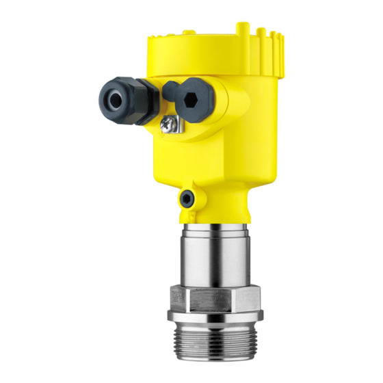
Housing cover, optionally available with indicating and adjustment module PLICSCOM The components are available in different versions. Fig. 1: Example of a VEGABAR 55 with process fitting G1½ A and plastic housing Housing cover with integrated PLICSCOM (optional) Housing with electronics Process fitting with measuring cell... -
Page 8: Principle Of Operation
In addition to the type label outside, you can also find the serial number on the inside of the instrument. 3.2 Principle of operation VEGABAR 55 is a pressure transmitter for use in the chemical, food Application area processing and pharmaceutical industries. Depending on the version, it is used for level, gauge, absolute pressure or vacuum measurement. -
Page 9: Packaging, Transport And Storage
Flanges are available in different versions according to the following Flanges standards: DIN 2501, EN 1092-1, ANSI B 16.5, JIS B 2210-1984, GOST 12821-80. You will find additional information in the supplementary instructions manual "Flanges according to DIN-EN-ASME-JIS" (Document-ID 31088). VEGABAR 55 • 4 … 20 mA... - Page 10 The electronics module is a replacement part for pressure transmitter Electronics module VEGABAR. One version is available for each type of signal output. You find further information in the operating instructions "Electronics module VEGABAR series 50 and 60 " (Document-ID 30175). VEGABAR 55 • 4 … 20 mA...
-
Page 11: Mounting
Rain and condensation water can thus drain off. This applies mainly to outdoor mounting as well as installation in areas where high humidity is expected (e.g. through cleaning processes) or on cooled or heated vessels. Fig. 2: Measures against moisture penetration VEGABAR 55 • 4 … 20 mA... - Page 12 Higher process temperatures often mean also higher ambient Temperature limits temperatures. Make sure that the upper temperature limits stated in chapter "Technical data" for the environment of the electronics housing and connection cable are not exceeded. VEGABAR 55 • 4 … 20 mA...
-
Page 13: Mounting Steps
Fig. 4: Temperature ranges Process temperature Ambient temperature 4.2 Mounting steps For mounting VEGABAR 55, a welded socket is required. You can find Welding the socket these components in the supplementary instructions manual "Welded socket and seals". Use the seal belonging to the instrument or a suitable, product-... -
Page 14: Mounting Steps External Housing
The socket housing can be displaced by 180° to the wall mounting plate. Warning: The four screws of the socket housing must only be hand-screwed. A torque > 5 Nm (3.688 lbf ft) can damage the wall mounting plate. VEGABAR 55 • 4 … 20 mA... -
Page 15: Connecting To Power Supply
The signal conditioning instruments VEGAMET 624 and 625 as well as VEGASCAN 693 have a digital sensor recognition. When connecting VEGABAR 55, a software version from 1.92 is required with the signal conditioning instrument. For software update move under "www.vega. -
Page 16: Connection Procedure
Remove approx. 10 cm of the cable mantle, strip approx. 1 cm insulation from the individual wires Insert the cable through the cable gland into the sensor Lift the opening levers of the terminals with a screwdriver (see following illustration) VEGABAR 55 • 4 … 20 mA... - Page 17 The electrical connection is finished. Fig. 6: Connection steps 6 and 7 Proceed as follows: IP 68 version with exter- nal housing Loosen the four screws on the housing socket with an Allen key size 4 VEGABAR 55 • 4 … 20 mA...
- Page 18 5 cm of the cable mantle, strip approx. 1 cm insulation from the ends of the individual wires. After shortening the cable, fasten the type plate with sup- port back onto the cable. VEGABAR 55 • 4 … 20 mA...
-
Page 19: Wiring Plan, Single Chamber Housing
Fig. 8: Electronics and connection compartment, single chamber housing Spring-loaded terminals for voltage supply Ground terminal for connection of the cable screen Wiring plan 4...20mA Display Fig. 9: Wiring plan, single chamber housing Voltage supply/Signal output VEGABAR 55 • 4 … 20 mA... -
Page 20: Wiring Plan - Version Ip 66/Ip 68, 1 Bar
(+) and blue (-) to power supply or to the processing system Shielding 5.5 Wiring plan, external housing with version IP 68 Overview Fig. 11: VEGABAR 55 in IP 68 version 25 bar and axial cable outlet, external housing VEGABAR 55 • 4 … 20 mA... - Page 21 Fig. 12: Electronics and connection compartment Plug connector for VEGACONNECT (I²C interface) Spring-loaded terminals for connection of the external indication VEGADIS Cable gland to VEGABAR Ground terminal for connection of the cable screen Spring-loaded terminals for voltage supply VEGABAR 55 • 4 … 20 mA...
-
Page 22: Switch On Phase
I 2 C Fig. 14: Wiring plan external electronics Power supply 5.6 Switch on phase After connecting VEGABAR 55 to power supply or after a voltage Switch on phase recurrence, the instrument carries out a self-check for approx. 30 seconds:... - Page 23 Output signal jumps briefly (approx. 10 seconds) to the set fault current Then the corresponding current is outputted to the cable (the value corresponds to the actual level as well as the settings already carried out, e.g. factory setting). VEGABAR 55 • 4 … 20 mA...
-
Page 24: Set Up With The Indicating And Adjustment Module Plicscom
Screw housing cover with inspection window tightly back on Removal is carried out in reverse order. The indicating and adjustment module is powered by the sensor, an additional connection is not necessary. VEGABAR 55 • 4 … 20 mA... - Page 25 Fig. 15: Insert indicating and adjustment module Note: If you intend to retrofit the instrument with an indicating and adjustment module for continuous measured value indication, a higher cover with an inspection glass is required. VEGABAR 55 • 4 … 20 mA...
-
Page 26: Adjustment System
The functions of the individual keys are shown in the above illustration. Approx. 10 minutes after the last pressing of a key, an automatic reset to measured value indication is triggered. Any values not confirmed with [OK] will not be saved. VEGABAR 55 • 4 … 20 mA... -
Page 27: Setup Procedure
6 Set up with the indicating and adjustment module PLICSCOM 6.4 Setup procedure VEGABAR 55 can be used for level as well as for process pressure Level or process pres- measurement. Default setting is level measurement. The mode can be sure measurement changed in the adjustment menu. - Page 28 Select the requested unit, e.g. kg/dm³ with [->] and confirm with [OK], the submenu "Density" appears. Unit of measurement Density 0001000 kg/dm³ Enter the requested density value with [->] and [+], confirm with [OK] and move to position correction with [->]. VEGABAR 55 • 4 … 20 mA...
- Page 29 Confirm with [+] and move to max. adjustment with [->]. The min. adjustment is finished. Information: For an adjustment with filling, simply enter the actual measured value indicated at the bottom of the display. Selection options: °C, °F. VEGABAR 55 • 4 … 20 mA...
- Page 30 The editing procedure can be aborted with [ESC] or the displayed limit value can be accepted with [OK]. Process pressure measurement Set up VEGABAR 55 in the following sequence: Parameter ad- justment "Proc- Select application "Process pressure measurement"...
- Page 31 The actual measured value is displayed in addition to the menu items for zero/span adjustment. VEGABAR 55 is preset to application "Level measurement". Proceed Select application as follows when switching over to application "Process pressure "Process pressure...
- Page 32 53 mbar Select with [->], e.g. to accept actual measured value. Position correction Accept current measured value? ▶ Accept Edit Confirm with [OK] and move to min.(zero) adjustment with [->]. Selection options: °C, °F. VEGABAR 55 • 4 … 20 mA...
- Page 33 Confirm with [OK] and move to the menu overview with [ESC]. The span adjustment is finished. Information: For an adjustment with pressure, simply enter the actual measured value indicated at the bottom of the display. VEGABAR 55 • 4 … 20 mA...
- Page 34 [->] key. Caution: Note the following, if VEGABAR 55 is used as part of an overfill protection system according to WHG: If a linearisation curve is selected, the measuring signal is no longer compulsorily linear proportional to the level.
- Page 35 The values of the following menu items are not reset with "Reset: Menu section Function Reset value Basic settings Position correction no reset no reset Display Lighting no reset Service no reset Language HART mode no reset VEGABAR 55 • 4 … 20 mA...
- Page 36 You will find a detailed description of these menu items in the operating instructions manual "Indicating and adjustment module". Special parameters are parameters which are set customer-specifically on the service level with the adjustment software PACTware. VEGABAR 55 • 4 … 20 mA...
-
Page 37: Menu Schematic
Basic adjustment ▶ Display Diagnostics Service Info Displayed value Displayed value Display unit ▼ Scaling 0 % = 0.0 ▼ ▼ Pressure Scaled Volume ▼ 100 % = 100.0 Lighting ▼ Switched off VEGABAR 55 • 4 … 20 mA... - Page 38 Deutsch Fail.mode: < 3.6 mA ▼ Min. current: 3.8 mA ▼ max. current: 20.5 mA ▼ HART mode Copy sensor data ▼ Deactivated! Standard Copy sensor data? Enable? Address 0 Application ▼ Level VEGABAR 55 • 4 … 20 mA...
- Page 39 Info Basic adjustment Display Diagnostics Service ▶ Info Instrument type Date of manufacture Last change using PC Sensor characteristics 1st October 2009 Software version Display now? Serial number 3.80 1st October 2009 12345678 VEGABAR 55 • 4 … 20 mA...
-
Page 40: Saving The Parameter Adjustment Data
They are hence available for multiple use or service purposes. If VEGABAR 55 is equipped with an indicating and adjustment module, the most important data can be read out of the sensor into indicating and adjustment module. -
Page 41: Maintenance And Fault Rectification
DTM. In many cases, the causes can be determined this way and faults rectified. However, should these measures not be successful, call the VEGA 24 hour service hotline service hotline in urgent cases under the phone no. +49 1805 858550. - Page 42 à Exchange instrument or return instrument for repair E017 Adjustment span too small à repeat with modified values Fault message can also appear if the pressure is higher than the nominal range. VEGABAR 55 • 4 … 20 mA...
-
Page 43: Calculation Of Total Deviation (Similar To Din 16086)
Pressure measurement in the pipeline 8 bar (800 KPa) Example Product temperature 50 °C, hence within the compensated range VEGABAR 55 with measuring range 25 bar Calculation of the set Turn Down: TD = 10 bar/8 bar, TD = 1.25 Basic accuracy digital output signal in percent: = √((F... -
Page 44: Exchanging The Electronics Module
These are not included in the electronics module without serial number. The serial number is stated on the type label of VEGABAR 55 or on the delivery note. 7.5 Software update... -
Page 45: Instrument Repair
Prepare update to the instrument via VEGACONNECT. Start PACTware and provide connection to the sensor, e.g. via the VEGA project assistant. Close the parameter window of the sensor, as far as open. Go in the PACTware menu bar to "Instrument data", "Additional Load software into sen- functions"... -
Page 46: Dismount
Correct disposal avoids negative effects to persons and environment and ensures recycling of useful raw materials. Materials: see chapter "Technical data" If you have no possibility to dispose of the old instrument professionally, please contact us concerning return and disposal. VEGABAR 55 • 4 … 20 mA... -
Page 47: Supplement
PE hard cable Weight approx. 0.8 … 8 kg (1.764 … 17.64 lbs), depending on process fitting Output variable Output signal 4 … 20 mA Signal resolution 1.6 µA Failure signal output current VEGABAR 55 • 4 … 20 mA... - Page 48 Adjustment range of the zero/span adjustment relating to the nominal measuring range: zero -20 … +95 % -120 … +120 % Span Difference between zero and span max. 120 % of the nominal range Values less than -1 bar cannot be set. VEGABAR 55 • 4 … 20 mA...
- Page 49 -15 psig 0 … 15 psig 500 psig -15 psig 0 … 35 psig 700 psig -15 psig 0 … 70 psig 950 psig -15 psig 0 … 150 psig 1300 psig -15 psig VEGABAR 55 • 4 … 20 mA...
- Page 50 Turn down > 5 : 1 < 0.04 % x TD Deviation with version 0.1 % Turn down 1 : 1 up to 5 : 1 < 0.1 % Incl. non-linearity, hysteresis and non-repeatability. VEGABAR 55 • 4 … 20 mA...
- Page 51 PN 16/PN 40 or 150 lb/300 lb Flange 316L Product temperature -12 … +140 °C (+10 … +284 °F) Standard with extenation, extended thread or -12 … +140 °C (+10 … +284 °F) Clamp 2½" VEGABAR 55 • 4 … 20 mA...
- Page 52 1 x closing cap ½ NPT, 1 x blind plug ½ NPT Tested according to the regulations of German Lloyd, GL directive 2. Tested according to EN 60068-2-27. Depending on the version M12 x 1, according to DIN 43650, Harting, 7/ 8" FF. VEGABAR 55 • 4 … 20 mA...
- Page 53 Min. bending radius at 25 °C/77 °F 25 mm (0.985 in) Diameter approx. 8 mm (0.315 in) Colour - standard PE Black Depending on the version M12 x 1, according to DIN 43650, Harting, 7/ 8" FF. VEGABAR 55 • 4 … 20 mA...
- Page 54 EEx-ia instrument 20 … 30 V DC EEx-d-ia instrument 20 … 36 V DC Permissible residual ripple < 100 Hz < 1 V 100 Hz … 10 kHz < 10 mV see diagram Load VEGABAR 55 • 4 … 20 mA...
- Page 55 Instruments with gauge pressure measuring ranges cannot detect the am- bient pressure when submerged, e.g. in water. This can lead to falsification of the measured value. Only with instruments with absolute pressure ranges. VEGABAR 55 • 4 … 20 mA...
- Page 56 Depending on the version, instruments with approvals can have different technical data. For these instruments, the corresponding approval documents have to be taken into account. These are part of the delivery or can be downloaded under www.vega.com via "VEGA Tools" and "serial number search" as well as via "Downloads" and "Approvals".
-
Page 57: Dimensions
M16x1,5 M20x1,5/ M20x1,5 ½ NPT M20x1,5/ ½ NPT Fig. 19: Housing versions (with integrated PLICSCOM the housing is 9 mm/0.35 in higher) Plastic housing Stainless steel housing Aluminium double chamber housing Aluminium housing VEGABAR 55 • 4 … 20 mA... - Page 58 Fig. 20: Housing versions in protection IP 66/IP 68, 1 bar (with integrated indicating and adjustment module the housing is 9 mm/0.35 in higher) Stainless steel housing Special steel casting housing Aluminium double chamber housing Aluminium housing VEGABAR 55 • 4 … 20 mA...
- Page 59 42mm ") 40mm ") 90 mm (3 ") 110 mm (4 ") ~ 66 mm (2 ") Fig. 21: Transmitter and external housing with IP 68 version Lateral cable outlet Axial cable outlet VEGABAR 55 • 4 … 20 mA...
- Page 60 ") BA / BB Fig. 22: VEGABAR 55 - threaded fitting: GG = G1½ A, GL = G1½ A thread length 55 mm, GN = 1½ NPT, BA/BB = M44 x 1.25, BE = M56 x 1.25 VEGABAR 55 • 4 … 20 mA...
- Page 61 ") ") Fig. 23: VEGABAR 55 - hygienic fitting: CA/CF = Tri-Clamp 2"/Tri-Clamp 2½", CB = Tri-Clamp 3", LA = hygienic fitting with compression nut F40, SA = SMS DN 38, SB = SMS DN 51 VEGABAR 55 • 4 … 20 mA...
- Page 62 ") Fig. 24: VEGABAR 55 - hygienic fitting: TA = Tuchenhagen Varivent DN 32, RV/RW = bolting DN 40/DN 50 nach DIN 11851, AA = DRD, KA = cone DN 40, TS = terminal socket according to DIN 11864-3 Form A DN40/PN40...
- Page 63 3“ 150 lbs 6“ 4xø 5“ " " " " Fig. 25: VEGABAR 55 - flange connection Flange connection according to DIN 2501 Flange fitting according to ANSI B16.5 Flange with extension Order-specific VEGABAR 55 • 4 … 20 mA...
- Page 64 Les lignes de produits VEGA sont globalement protégées par des droits de propriété intellectuelle. Pour plus d'informations, on pourra se référer au site http://www.vega. VEGA lineas de productos están protegidas por los derechos en el campo de la propiedad industrial. Para mayor información revise la pagina web http://www.vega.com Линии...
- Page 65 Mounting position 11 Position correction 29, 32 Power supply 8, 15 Pressure compensation 12 Process conditions 11 Replacement parts, Electronics module 10 Reset 35 Span adjustment 33 Temperature limits 12 Total deviation 43 VEGABAR 55 • 4 … 20 mA...
- Page 66 Index VEGABAR 55 • 4 … 20 mA...
- Page 67 Index VEGABAR 55 • 4 … 20 mA...
- Page 68 All statements concerning scope of delivery, application, practical use and operating conditions of the sensors and processing systems correspond to the information avail- able at the time of printing. © VEGA Grieshaber KG, Schiltach/Germany 2009 Subject to change without prior notice 36733-EN-091008...
Need help?
Do you have a question about the VEGABAR 55 and is the answer not in the manual?
Questions and answers