Vega VEGABAR 54 Operating Instructions Manual
Pressure transmitter with mini-certec measuring cell
Hide thumbs
Also See for VEGABAR 54:
- Operating instructions manual (84 pages) ,
- Product information (28 pages) ,
- Operating instructions manual (72 pages)

Subscribe to Our Youtube Channel
Related Manuals for Vega VEGABAR 54


Summary of Contents for Vega VEGABAR 54
-
Page 1: Operating Instructions
Operating Instructions Pressure transmitter with MINI-CERTEC ® measuring cell VEGABAR 54 Foundation Fieldbus - climate compensated Document ID: 36791... -
Page 2: Table Of Contents
6.10 Saving the parameter adjustment data ................37 Set up with PACTware and other adjustment programs Connect the PC ......................38 Parameter adjustment with PACTware ................39 Parameter adjustment with AMS™................. 39 Saving the parameter adjustment data ................39 VEGABAR 54 • Foundation Fieldbus - climate compensated... - Page 3 10.1 Technical data ........................ 46 10.2 Information on Foundation Fieldbus ................55 10.3 Dimensions ........................58 Supplementary documentation Information: Supplementary documents appropriate to the ordered version come with the delivery. You can find them listed in chapter "Product descrip- tion". Editing status: 2014-04-24 VEGABAR 54 • Foundation Fieldbus - climate compensated...
-
Page 4: About This Document
This arrow indicates a single action. Sequence of actions Numbers set in front indicate successive steps in a procedure. Battery disposal This symbol indicates special information about the disposal of bat- teries and accumulators. VEGABAR 54 • Foundation Fieldbus - climate compensated... -
Page 5: For Your Safety
During work on and with the device the required personal protective equipment must always be worn. Appropriate use VEGABAR 54 is a pressure transmitter for measurement of gauge pressure and vacuum. You can find detailed information about the area of application in chapter "Product description". Operational reliability is ensured only if the instrument is properly used according to the specifications in the operating instructions manual as well as possible supplementary instructions. -
Page 6: Safety Label On The Instrument
With respect to compatibility, the NAMUR recommendation NE 53 is fulfilled. This applies also to the corresponding display and adjust- ment components. VEGA instruments are generally upward and downward compatible. • Sensor software for DTM VEGABAR 54 HART, PA or FF • DTM VEGABAR 54 for adjustment software PACTware • Display and adjustment module for sensor software The parameter adjustment of the basic sensor functions is independ- ent of the software version. -
Page 7: Product Description
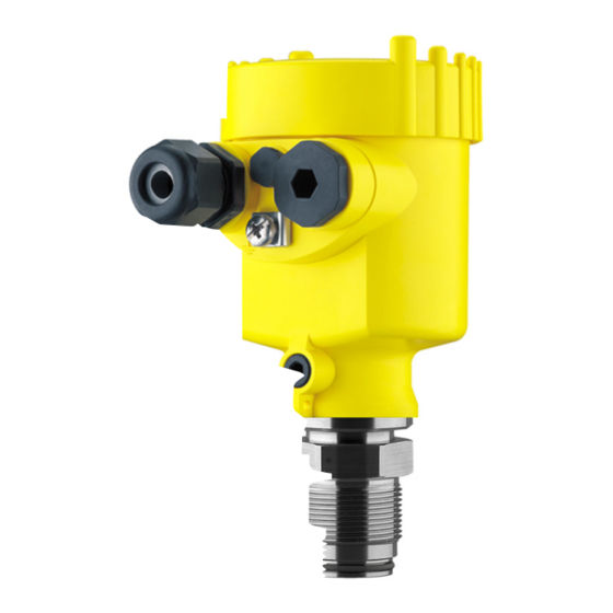
Constituent parts The VEGABAR 54 consists of the components: • Process fitting with measuring cell • Housing with electronics, optionally available with plug connector • Housing cover, optionally available with display and adjustment module The components are available in different versions. VEGABAR 54 • Foundation Fieldbus - climate compensated... - Page 8 3 Product description Fig. 1: Example of a VEGABAR 54 with process fitting G1 A and plastic housing Housing cover with integrated PLICSCOM (optional) Housing with electronics Process fitting with measuring cell Type label The type label contains the most important data for identification and use of the instrument: VEGABAR 54 • Foundation Fieldbus - climate compensated...
-
Page 9: Principle Of Operation
• Software from 3.82 Principle of operation Application area VEGABAR 54 - climate compensated is a pressure transmitter for use in the paper and food processing industries as well as in water/waste water applications under difficult conditions (cold medium and warm, humid environment). Depending on the version, the pressure transmitter is used for meas- urement of level, gauge pressure or vacuum. -
Page 10: Operation
IEC 61158-2 DD/CFF The DD (Device Descriptions) and CFF (capability files) necessary for planning and configuration of your FF (Foundation Fieldbus) com- munication network are available in the download area of the VEGA homepage www.vega.com under "Services - Downloads - Software - Foundation Fieldbus". The appropriate certificates are also available there. A CD with the appropriate files and certificates can be ordered via e-mail under info@de.vega.com or by phone from one of the VEGA agencies under the order number "DRIVER.S". -
Page 11: Packaging, Transport And Storage
VEGADIS 61 is suitable for external measured value indication and adjustment unit adjustment of plics® sensors. It is connected to the sensor with an up to 25 m long, four-wire, screened standard cable. VEGABAR 54 • Foundation Fieldbus - climate compensated... - Page 12 Electronics module The electronics module is a replacement part for pressure transmitter VEGABAR. One version is available for each type of signal output. You find further information in the operating instructions "Electronics module VEGABAR series 50 and 60 " (Document-ID 30175). VEGABAR 54 • Foundation Fieldbus - climate compensated...
-
Page 13: Mounting
Fig. 3: Measures against moisture penetration Ventilation and pressure The ventilation of the electronics housing as well as the atmospheric compensation pressure compensation for the measuring cell are realised via a filter element in the area of the cable gland. VEGABAR 54 • Foundation Fieldbus - climate compensated... - Page 14 Higher process temperatures often mean also higher ambient temperatures. Make sure that the upper temperature limits stated in chapter "Technical data" for the environment of the electronics hous- ing and connection cable are not exceeded. Fig. 5: Temperature ranges Process temperature Ambient temperature VEGABAR 54 • Foundation Fieldbus - climate compensated...
-
Page 15: Mounting Steps
Sealing/Screwing in Use the seal fitting belonging to the instrument, or in case of NPT threaded versions connections, a high-resistance sealing material. → Screw VEGABAR 54 into the welded socket. Tighten the hexagon on the process fitting with a suitable wrench. Wrench size, see chapter "Dimensions". Warning: The housing must not be used to screw the instrument in! Applying tightening force can damage internal parts of the housing. -
Page 16: Connecting To Power Supply
The cable screens to the power supply unit and to the next distributor must be connected to each other and also connected to ground potential via a ceramic capacitor (e.g. 1 nF, 1500 V). The VEGABAR 54 • Foundation Fieldbus - climate compensated... -
Page 17: Connection Procedure
11. Tighten the compression nut of the cable entry gland. The seal ring must completely encircle the cable 12. Screw the housing cover back on The electrical connection is finished. VEGABAR 54 • Foundation Fieldbus - climate compensated... - Page 18 1. Loosen the four screws on the housing base with an Allen key size 4 2. Remove the mounting plate from the housing socket Fig. 8: Components of the external housing Screws Wall mounting plate Cable gland VEGABAR 54 • Foundation Fieldbus - climate compensated...
-
Page 19: Wiring Plan, Single Chamber Housing
Remove approx. 5 cm of the cable mantle, strip approx. 1 cm insulation from the ends of the individual wires. After shortening the cable, fasten the type plate with support back on the cable. VEGABAR 54 • Foundation Fieldbus - climate compensated... -
Page 20: Wiring Plan, Double Chamber Housing
I ² C 5 6 7 8 Fig. 11: Electronics compartment, double chamber housing Simulation switch ("on" = simulation mode) Connection for VEGACONNECT (I²C interface) Internal connection cable to the connection compartment VEGABAR 54 • Foundation Fieldbus - climate compensated... -
Page 21: Wiring Plan - Version Ip 66/Ip 68, 1 Bar
Wiring plan - version IP 66/IP 68, 1 bar Wire assignment, con- nection cable Fig. 14: Wire assignment, connection cable brown (+) and blue (-) to power supply or to the processing system Shielding VEGABAR 54 • Foundation Fieldbus - climate compensated... -
Page 22: Wiring Plan, External Housing With Version Ip 68
5 Connecting to power supply Wiring plan, external housing with version IP 68 Overview Fig. 15: VEGABAR 54 in IP 68 version 25 bar and axial cable outlet, external housing Electronics and terminal compartment Typ: Display I ² C 5 6 7 8 Fig. -
Page 23: Switch-On Phase
Fig. 18: Wiring plan external electronics Voltage supply Switch-on phase After VEGABAR 54 is connected to voltage supply or after voltage Switch-on phase recurrence, the instrument carries out a self-check for approx. 30 seconds. The following steps are carried out: •... - Page 24 Then the current measured value will be displayed and the corre- sponding digital output signal will be outputted to the cable. The values correspond to the actual measured level as well as to the settings already carried out, e.g. default setting. VEGABAR 54 • Foundation Fieldbus - climate compensated...
-
Page 25: Set Up With The Display And Adjustment Module Plicscom
4. Screw housing cover with inspection window tightly back on Disassembly is carried out in reverse order. The display and adjustment module is powered by the sensor, an ad- ditional connection is not necessary. VEGABAR 54 • Foundation Fieldbus - climate compensated... -
Page 26: Adjustment System
Adjustment system Fig. 20: Display and adjustment elements LC display Indication of the menu item number Adjustment keys • Key functions [OK] key: VEGABAR 54 • Foundation Fieldbus - climate compensated... -
Page 27: Setup Steps
HART mode Standard Address 0 Level or process pres- VEGABAR 54 can be used for level as well as for process pressure sure measurement measurement. Default setting is level measurement. The mode can be changed in the adjustment menu. Depending on the application only the respective subchapter "Level or process pressure measurement" is of importance. There, you find... - Page 28 Proceed as follows: 1. Push the [OK] button in the measured value display, the menu overview is displayed. Selection options: mbar, bar, psi, Pa, kPa, MPa, inHg, mmHg, inH VEGABAR 54 • Foundation Fieldbus - climate compensated...
- Page 29 2. Select with [->], e.g. to accept actual measured value. Position correction Accept current measured value? ▶ Accept Edit 3. Confirm with [OK] and move to min.(zero) adjustment with [->]. Carry out min. adjustment Proceed as follows: 1. Edit the % value in the menu item "Min. adjustment" with [OK]. Selection options: °C, °F. VEGABAR 54 • Foundation Fieldbus - climate compensated...
- Page 30 If the adjustment ranges are exceeded, the message "Outside param- eter limits" appears. The editing procedure can be aborted with [ESC] or the displayed limit value can be accepted with [OK]. Process pressure measurement Parameter adjustment Set up VEGABAR 54 in the following sequence: "Process pressure meas- 1. Select application "Process pressure measurement" urement" 2. Select the unit of measurement 3. Carry out a position correction 4. Carrying out zero adjustment...
- Page 31 1. Push the [OK] button in the measured value display, the menu overview is displayed. ▶ Basic adjustment Display Diagnostics Service Info Selection options: mbar, bar, psi, Pa, kPa, MPa, inHg, mmHg, inH VEGABAR 54 • Foundation Fieldbus - climate compensated...
- Page 32 1. Edit the mbar value in the menu item "zero" with [OK]. Zero 000.0 % +0000.0 mbar 0000.0 mbar 2. Set the requested mbar value with [+] and [->]. 3. Confirm with [+] and move to span adjustment with [->]. The zero adjustment is finished. Selection options: °C, °F. VEGABAR 54 • Foundation Fieldbus - climate compensated...
- Page 33 Linearisation curve Linear Enter the requested parameters via the appropriate keys, save your settings and jump to the next menu item with the [->] key. VEGABAR 54 • Foundation Fieldbus - climate compensated...
- Page 34 Menu section Function Reset value Basic settings Zero/Min. adjustment Measuring range begin Span/Max. adjustment Measuring range end Density 1 kg/l Density unit kg/l With instruments with signal output 4 … 20 mA/HART VEGABAR 54 • Foundation Fieldbus - climate compensated...
-
Page 35: Menu Schematic
Menu schematic Information: Depending on the version and application, the highlighted menu windows may not always be available. Special parameters are parameters which are set customer-specifically on the service level with the adjustment software PACTware. VEGABAR 54 • Foundation Fieldbus - climate compensated... - Page 36 Displayed value Backlight ▼ AI-Out Switched off Service Basic adjustment Display Diagnostics ▶ Service Info Simulation Reset Language Copy sensor data ▼ ▼ German Copy sensor data? Start simulation Select reset Application Enable? Level VEGABAR 54 • Foundation Fieldbus - climate compensated...
-
Page 37: Saving The Parameter Adjustment Data
They are thus available for multiple use or service purposes. If VEGABAR 54 is equipped with a display and adjustment module, the most important data can be read out of the sensor into the display and adjustment module. -
Page 38: Set Up With Pactware And Other Adjustment Programs
Fig. 22: Connection via VEGACONNECT externally I²C bus (com.) interface on the sensor I²C connection cable of VEGACONNECT VEGACONNECT USB cable to the PC Necessary components: • VEGABAR 54 • PC with PACTware and suitable VEGA DTM VEGABAR 54 • Foundation Fieldbus - climate compensated... -
Page 39: Parameter Adjustment With Pactware
PACTware and the VEGA DTMs. Note: Keep in mind that for setup of VEGABAR 54, DTM-Collection in the actual version must be used. All currently available VEGA DTMs are included as a DTM Collection on a CD. -
Page 40: Maintenance And Fault Rectification
24 hour service hotline Should these measures not be successful, please call in urgent cases the VEGA service hotline under the phone no. +49 1805 858550. The hotline is manned 7 days a week round-the-clock. Since we offer this service worldwide, the support is only available in the English language. The service is free, only standard call charges are incurred. -
Page 41: Calculation Of Total Deviation (According To Din 16086)
+ (F perf With: • : Total deviation total • : Basic accuracy perf • : Long-term drift stab Fault message can also appear if the pressure is higher than the nominal range. VEGABAR 54 • Foundation Fieldbus - climate compensated... - Page 42 Pressure measurement in the pipeline 8 bar (800 KPa) Product temperature 10 °C, reference temperature 20 °C Calculation ΔT: ΔT = 20 °C - 10 °C = 10 K VEGABAR 54 climate compensated, with measuring range 25 bar Calculation of the set Turn Down: TD = 25 bar/8 bar, TD = 3.1 Basic accuracy digital output signal in percent: = √((F...
-
Page 43: Exchanging The Electronics Module
The electronics module with serial number includes order- specific data such as factory setting, seal material etc. These are not included in the electronics module without serial number. The serial number is stated on the type label of VEGABAR 54 or on the delivery note. Software update The software version of VEGABAR 54 can be determined as follows: •... -
Page 44: How To Proceed If A Repair Is Needed
• Attach the completed form and, if need be, also a safety data sheet outside on the packaging • Please contact the agency serving you to get the address for the return shipment. You can find the agency on our home page www.vega.com. VEGABAR 54 • Foundation Fieldbus - climate compensated... -
Page 45: Dismounting
WEEE directive. Correct disposal avoids negative effects on humans and the environ- ment and ensures recycling of useful raw materials. Materials: see chapter "Technical data" If you have no way to dispose of the old instrument properly, please contact us concerning return and disposal. VEGABAR 54 • Foundation Fieldbus - climate compensated... -
Page 46: Supplement
Ʋ Connection cable between transmitter and external electronics housing with IP 68 version Ʋ Type label support on connection PE hard cable Ʋ Connection cable with IP 68 1 bar PE, PUR version VEGABAR 54 • Foundation Fieldbus - climate compensated... - Page 47 Fig. 23: Sudden change of the process variable. t : dead time; t : rise time; t : jump response time Process variable Output signal Dead time ≤ 150 ms Rise time ≤ 100 ms (10 … 90 %) Step response time ≤ 250 ms (ti: 0 s, 10 … 90 %) VEGABAR 54 • Foundation Fieldbus - climate compensated...
- Page 48 -1 … +1.5 bar/-100 … +150 kPa +50 bar/+5000 kPa -1 bar/-100 kPa -1 … +5 bar/-100 … +500 kPa +65 bar/+6500 kPa -1 bar/-100 kPa Values less than -1 bar cannot be set. VEGABAR 54 • Foundation Fieldbus - climate compensated...
- Page 49 Ʋ Air pressure 860 … 1060 mbar/86 … 106 kPa (12.5 … 15.4 psig) Determination of characteristics Limit point adjustment according to IEC 61298-2 Characterstic curve Linear Reference installation position upright, diaphragm points downward VEGABAR 54 • Foundation Fieldbus - climate compensated...
- Page 50 15 … 900 psig -0.1 … 0.1 bar/-10 … 10 kPa < (0.05 + 0.05 x TD)%/10K < (0.05 + 0.1 x TD)%/10K 1.5 … 1.5 psig Incl. non-linearity, hysteresis and non-repeatability. VEGABAR 54 • Foundation Fieldbus - climate compensated...
- Page 51 -0.1 … 0.1 bar/-10 … 10 kPa -1.5 … 1.5 psig < (1 % x TD)/year -0.2 … 0.2 bar/-20 … 20 kPa -3 … 3 psig < (1 % x TD)/year VEGABAR 54 • Foundation Fieldbus - climate compensated...
-
Page 52: Ambient Conditions
-15 … +120 °C (-4 … +248 °F) Vibration resistance mechanical vibrations with 4 g and 5 … 100 Hz tested according to the regulations of German Lloyd, GL char- acteristics 2. Shock resistance Acceleration 100 g/6 ms With process fitting PVDF, max. 100 °C (212 °F). Tested according to EN 60068-2-27. VEGABAR 54 • Foundation Fieldbus - climate compensated... - Page 53 Ʋ Standard length 5 m (16.4 ft) Ʋ Max. length 1000 m (3281 ft) Ʋ Min. bending radius at 25 °C/77 °F 25 mm (0.985 in) Ʋ Diameter approx. 8 mm (0.315 in) Depending on the version M12 x 1, according to ISO 4400, Harting, 7/8" FF. VEGABAR 54 • Foundation Fieldbus - climate compensated...
- Page 54 Ʋ Ex d instrument 16 … 32 V DC Operating voltage with illuminated display and adjustment module Ʋ Non-Ex instrument 12 … 32 V DC Ʋ Ex-ia instrument 12 … 24 V DC Depending on the version M12 x 1, according to ISO 4400, Harting, 7/8" FF. VEGABAR 54 • Foundation Fieldbus - climate compensated...
-
Page 55: Information On Foundation Fieldbus
Diagram, adjustment The following illustration shows the function of the adjustment: Instruments with gauge pressure measuring ranges cannot detect the ambient pressure when submerged, e.g. in water. This can lead to falsification of the measured value. Only with instruments with absolute pressure ranges. VEGABAR 54 • Foundation Fieldbus - climate compensated... - Page 56 – includes sensor unit: bar, PSI …; only unit part of DS-68 is writable • simulate_primary_value • simulate_secondary_value_1 • simulate_secondary_value_2 • device status – "0: ""OK"" 13: ""non-specific error"" 17: ""Cal span too small"" 34: ""EEPROM memory fault"" 36: ""ROM memory fault"" 37: ""RAM memory fault"" 40: ""non-specific hardware fault"" 41: ""Sensor element not found"" 42: ""No leaking pulse"" 43: ""No trigger signal"" 44: ""EMI error"" 113: ""Communication hardware fault""" • linearization type – Possible types of linearization are: linear, user defined, cylindrical lying container, spherical container – "0: ""Linear"" 1: ""User def"" 20: ""Cylindrical lying container"" 21: ""Spherical container""" • curve_points_1_10 VEGABAR 54 • Foundation Fieldbus - climate compensated...
- Page 57 – Minimum calibration span value allowed. Necessary to ensure that when calibration is done, the two calibrated points (high and low) are not too close together. Unit derives from 'Sen- sor_range.unit' • SCALE_IN – Min/max-adjustment: Upper and lower calibrated points of the sensor. Unit derives from 'Sen- sor_range.unit' • trimmed_value – Sensor value after the trim processing. Unit derives from 'Sensor_range.unit' • sensor_sn – Sensor serial number • temperature – Process temperature. Selected as input to AIFB by setting 'Channel' = 4. Unit derives from 'Temperature.unit' • temperature_unit – Unit code of 'Temperature', 'Max/Min_peak_temperature_value' – °C, °F, K, °R VEGABAR 54 • Foundation Fieldbus - climate compensated...
-
Page 58: Dimensions
½ NPT Fig. 27: Housing versions in protection IP 66/IP 68 (0.2 bar) - with integrated display and adjustment module the housing is 9 mm/0.35 in higher Single chamber version Double chamber version VEGABAR 54 • Foundation Fieldbus - climate compensated... - Page 59 ½ NPT Fig. 29: Housing versions in protection IP 66/IP 68 (1 bar) - with integrated display and adjustment module the housing is 9 mm/0.35 in higher Single chamber version Double chamber version VEGABAR 54 • Foundation Fieldbus - climate compensated...
- Page 60 Fig. 31: Housing versions in protection IP 66/IP 68 (1 bar) - with integrated display and adjustment module the housing is 9 mm/0.35 in higher Single chamber version, electropolished Single chamber version, precision casting Double chamber version, precision casting VEGABAR 54 • Foundation Fieldbus - climate compensated...
- Page 61 (4.33" x 3.54") (1.64") ~ 66 mm (2.60") 110 mm x 90 mm (4.33" x 3.54") Fig. 32: IP 68 version with external housing - plastic version Lateral cable outlet Axial cable outlet VEGABAR 54 • Foundation Fieldbus - climate compensated...
- Page 62 110 mm x 90 mm (4.33" x 3.54") 40mm (1.57") Fig. 33: External housing - Stainless steel version Lateral cable outlet Axial cable outlet Seal 2 mm (0.079 in) - only with 3A approval VEGABAR 54 • Foundation Fieldbus - climate compensated...
- Page 63 (1.58") (1.58") Fig. 34: VEGABAR 54, threaded connection: GA = G¾ A acc. to DIN 3852-E, GB = G½ A front-flush, GC = G1 A absolutely front-flush, GD = G1 A (DIN 3852-E) x 40 mm absolutely front-flush VEGABAR 54 • Foundation Fieldbus - climate compensated...
- Page 64 ø 52 mm (2.05") Fig. 35: VEGABAR 54, hygienic fitting: CI = Clamp DN15-20 according to DIN 32676, CD = Clamp 1" according to DIN 32676, ISO 2852, GK = G1 A conus 40° front-flush, RI = Ingold connection VEGABAR 54 • Foundation Fieldbus - climate compensated...
- Page 65 10 Supplement VEGABAR 54, hygienic fitting 2 ø 62,5 mm (2.46") Fig. 36: VEGABAR 54, hygienic fitting: RE = slotted nut DN 25 PN 40 acc. to DIN 11851 VEGABAR 54 • Foundation Fieldbus - climate compensated...
- Page 66 1“ 150 lbs 4.25" 0.56" 3.12" 4 x ø0,62" 2" 0.06" Fig. 37: VEGABAR 54, flange connection form C DIN 2501 Flange connection according to DIN 2501 Flange connection according to ANSI B16.5 VEGABAR 54 • Foundation Fieldbus - climate compensated...
- Page 67 10 Supplement VEGABAR 54, flange connection 2 4xø14 inch 4xø " " " " " " Fig. 38: VEGABAR 54, flange connection form B1, EN 1092-1 VEGABAR 54 • Foundation Fieldbus - climate compensated...
- Page 68 ") ") Fig. 39: VEGABAR 54, fitting for the paper industry: BA/BB = M44 x 1.25; BF = M30 x 1.5; BS = M30 x 1.5 for headbox, PC = PMC 1", PD = PMC 1¼", PE = PMC 1½"...
- Page 69 ø 24,7 mm ") ") ø 29,3 mm ø 29,3 mm ") ") Fig. 40: VEGABAR 54, connection for paper industry: VP = G1" for PASVE, VR = G1" for PASVE with O-ring seal VEGABAR 54 • Foundation Fieldbus - climate compensated...
- Page 70 Les lignes de produits VEGA sont globalement protégées par des droits de propriété intellec- tuelle. Pour plus d'informations, on pourra se référer au site www.vega.com. VEGA lineas de productos están protegidas por los derechos en el campo de la propiedad indus- trial. Para mayor información revise la pagina web www.vega.com.
- Page 71 Installation position 13 Maintenance 40 Max. adjustment 30 Min. adjustment 29 Moisture 13 Mounting external housing 15 Mounting, socket versions 15 Position correction 29, 32 Pressure compensation 13 Process conditions 13 Recycling 45 VEGABAR 54 • Foundation Fieldbus - climate compensated...
- Page 72 Subject to change without prior notice © VEGA Grieshaber KG, Schiltach/Germany 2014 VEGA Grieshaber KG Phone +49 7836 50-0 Am Hohenstein 113...
Need help?
Do you have a question about the VEGABAR 54 and is the answer not in the manual?
Questions and answers