Table of Contents
Advertisement
Quick Links
Advertisement
Table of Contents
Troubleshooting

Related Manuals for Vaisala PWD22


Summary of Contents for Vaisala PWD22
- Page 1 Present Weather Detector PWD22 UIDE M210543EN-B January 2004...
- Page 2 The contents are subject to change without prior notice. Please observe that this manual does not create any legally binding obligations for Vaisala towards the customer or end user. All legally binding commitments and agreements are included exclusively in the applicable supply contract or...
-
Page 3: Table Of Contents
ESD Protection ..............11 Trademarks................11 License Agreement ..............11 Warranty.................. 11 CHAPTER 2 PRODUCT OVERVIEW ................13 Introduction to Vaisala Present Weather Detector PWD22 13 Hardware Structure..............14 Sensing Element in PWD22 ..........14 PWT11 Transmitter............14 PWC22 Controller/Receiver........... 15 ®... - Page 4 INSTALLATION.................... 37 Selecting Location ..............37 Grounding and Lightning Protection ........39 Equipment Grounding ............39 Internal Grounding of PWD22 ..........39 Grounding the Remote Units and the Communication Cable39 Installation Procedure............40 Unpacking Instructions ............40 Unpacking Procedure............. 40 Storage................
- Page 5 Messages 5 and 6 ............60 Message 7 ..............61 Automatic Message Sending ..........62 Message Polling............. 62 Precipitation Sums..............64 List of Commands..............65 PWD22 Command Set............65 HELP................65 MES ................66 AMES................66 Weather Related Commands ..........67 WPAR ................68 WSET................
- Page 6 Message Exists but Visibility Value Does Not....101 Visibility Value is Continuously Too Good ......101 Visibility Constantly Too Low ..........102 PWD22 Reports Precipitation When There Is None ..102 PWD22 Reports Frozen Precipitation during Rain.... 103 PWD22 Electrical Troubleshooting ........103 Technical Support ..............
- Page 7 Location of Jumpers and Connectors on the PWC22 Processor/Receiver Board ............43 Figure 11 Installing PWD22 to the Support Arm ........43 Figure 12 Installing the Subassembly to the Mast with the Vaisala Clamp Assembly.................. 44 Figure 13 Testing the Connector.............. 44 Figure 14 Cabling Principle ..............
- Page 8 Values from STA message for Internal Monitoring ....111 Table 28 Internal Weather Types and Supported NWS Codes .... 117 Table 29 WMO SYNOP Codes (Table 4680, W ) Used by PWD22 118 Table 30 WMO METAR Codes (Table 4678) Used by PWD22.... 119 6_____________________________________________________________________ M210543EN-B...
-
Page 9: Chapter 1 General Information
This manual consists of the following chapters: - Chapter 1, General Information, provides general notes for the product. - Chapter 2, Product Overview, introduces Vaisala Present Weather Detector PWD22 features, advantages, and the product nomenclature. - Chapter 3, Functional Description, describes the functionality of the product. -
Page 10: Version Information
M210541EN-A Vaisala Visibility Sensor PWD10/20, User's Guide Feedback Vaisala Customer Documentation Team welcomes your comments and suggestions on the quality and usefulness of this publication. If you find errors or have other suggestions for improvement, please indicate the chapter, section, and page number. You can send comments to us by e-mail: manuals@vaisala.com... -
Page 11: Safety
Vaisala Present Weather Detector PWD22 delivered to you has been tested for safety and approved as shipped from the factory. Note the following precautions: WARNING The chassis of the PWD22 must be connected to a good electrical earth. ® Do not touch the surface of the RAINCAP Rain sensor plate. - Page 12 Operation of any electrical instrument in such an environment constitutes a definite safety hazard. CAUTION Do not modify or substitute parts in the instrument. Contact Vaisala or its authorized representative for repairs. The component boards including CMOS microchips should be CAUTION transported and stored in conductive packages.
-
Page 13: Esd Protection
Microsoft Corporation in the United States and/or other countries. License Agreement All rights to any software are held by Vaisala or third parties. The customer is allowed to use the software only to the extent that is provided by the applicable supply contract or Software License Agreement. - Page 14 User's Guide _______________________________________________________________________ This page intentionally left blank. 12____________________________________________________________________ M210543EN-B...
-
Page 15: Chapter 2 Product Overview
PWD22 is an intelligent, multi-variable sensor for automatic weather observing systems. The sensor combines the functions of a forward scatter visibility meter and a present weather sensor. PWD22 can measure the intensity and amount of both liquid and solid precipitation. As the detector is equipped with a background luminance sensor, it can also measure ambient light. -
Page 16: Hardware Structure
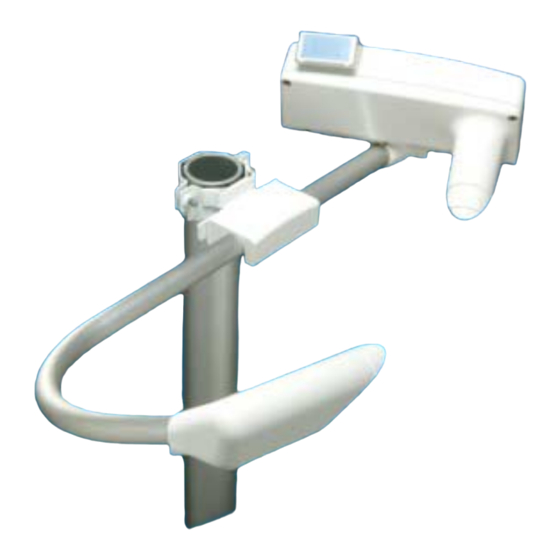
Hardware Structure PWD22 is a self-contained instrument that can be fastened to the side of the mast and into a crossarm using the mounting clamps. 0308-002 Figure 1 PWD22 Present Weather Detector The following numbers refer to Figure 1 above. -
Page 17: Pwc22 Controller/Receiver
The receiver is tilted 20° downwards. Therefore, in addition to a small side angle, the receiver unit measures light scattered at an angle of 45°. PWD22 contains enhanced signal processing functions, which allows for a wider measurement range. -
Page 18: Figure 2 Pwd22 Block Diagram
User's Guide _______________________________________________________________________ data processing is done by the embedded software. The main units are shown in Figure 2 below. °. ® 16____________________________________________________________________ M210543EN-B... -
Page 19: Using Pwd22
PWD22 is typically used as a component of a weather observing system. The PWD22 output is either a digital serial interface or an analog current signal. The digital serial interface can be configured into two different operating modes: the sensor can be set to send a data message automatically at selected intervals, or PWD22 can be polled by the host computer. -
Page 20: Product Nomenclature
A capacitive detector to sense water Rain Sensor droplets and/or moisture. Two plate in a 90-degree angle towards each other. Table 5 Nomenclature for Options of the Vaisala Present Weather Detector PWD Family Code Common Name Description PWL111 Background Luminance... -
Page 21: Functional Description
CHAPTER 3 FUNCTIONAL DESCRIPTION This chapter describes the functionality of the product. Vaisala Present Weather Detector PWD22 is an optical sensor that measures visibility (meteorological optical range, MOR), precipitation intensity, and precipitation type. The detector measures visibility using the principle of forward scatter measurement. Light scatters from particles whose diameter is in the order of magnitude of the wavelength of the light. -
Page 22: Optical Measurements
PWD22 has a small sample volume of about 0.1 liters (see Figure 3 above). This allows for independent particles to be measured even at relatively heavy precipitation intensities. -
Page 23: Light Receiver
1.0 using the DRY and WET commands as a setup. The frequency signal is measured once a second. The frequency is handled in the PWD22 internal units. The DRY value is about 800, which is also shown in the Status (STA) message. -
Page 24: Background Luminance Sensor Pwl111 (Optional)
If the relative humidity of the air is more than about 70 %, the surfaces produce a measurable signal even with no precipitation. In PWD22 this is used as an estimated humidity measurement. The estimated humidity is used to separate between dust and mist. -
Page 25: Blsc Command
0 or 1. Zero indicates night time and one indicates day time. See the example below: >BLSC 0 Disabling PWL111 The negative scale directs PWD22 to skip the background luminance action. See the example below: >BLSC -1 BLCAL Command... -
Page 26: Temperature Sensor
Figure 5 PWL111 Block Diagram Temperature Sensor The primary temperature sensor of PWD22 is a Pt100 thermistor attached to the crossarm. The temperature is measured once a minute using a high resolution A/D converter. The sensor crossarm temperature (TS) is used to select the default precipitation type. -
Page 27: Algorithm Description
The transfer function converts frequency into visibility (MOR). The transfer function has been defined with an accurate transmissometer (Vaisala MITRAS) as a reference. The instantaneous (15 s) visibility values are averaged to get a 1-minute and 10-minute average output values. The averages are calculated from extinction coefficient values to emulate human observations better. -
Page 28: Precipitation Intensity
In liquid precipitation the optical intensity is reported as such. When frozen precipitation is detected, PWD22 multiplies the optical intensity with a scaling factor to get an estimate of the water equivalent intensity. This scaling factor ®... -
Page 29: Precipitation Accumulation
Chapter 3________________________________________________________ Functional Description Precipitation Accumulation PWD22 calculates the accumulation of water (including the water content of snow) and snow. The water sum is automatically reset when it reaches 99.99 mm and the snow sum at 999 mm. There is also... -
Page 30: Liquid Precipitation
By definition, drizzle cannot be identified only by its size, but also by NOTE its origin (stratus cloud). PWD22 reports the instant weather code by the size information only. The 15-minute weather code in the PWD22 report is drizzle, when at least ten minutes of only drizzle precipitation has been observed. -
Page 31: Frozen Precipitation
6 °C. Mixed Precipitation PWD22 reports either rain and snow (WMO codes 67 and 68) or ice pellets (WMO codes 74, 75, and 76) when the intensity ratio is between 1 and Snow limit. The intensity is determined by estimating the water equivalent intensity and using the rain intensity limits. -
Page 32: Visibility Types
User's Guide _______________________________________________________________________ Visibility Types The weather type is determined from visibility, when precipitation is not detected. The visibility types for PWD22 are the following. Table 6 WMO SYNOP Code Limits Code 10-minute Visibility Average Weather Condition CLEAR (00) Higher than or equal to 10 km. No precipitation... -
Page 33: Weather Classes
"PRECIPITATION DURING THE PRECEDING HOUR" code is used. Weather Code Selection PWD22 presents the weather type using the World Meteorological Organization (WMO) code table 4680. Precipitation type is also reported using the United States National Weather Service (NWS) abbreviations. -
Page 34: Applications
User's Guide _______________________________________________________________________ PWD22 is presented in Appendix C, NWS and WMO Code Tables, on page 117. The weather type is selected every 15 seconds using the principles described earlier. Instant weather type will be selected from the 15-second types after Weather delay number of samples by weighted majority occurrences. -
Page 35: Memory Tests
Memory Tests After resetting, PWD22 tests and clears its SRAM data memory. It indicates an error by the Signal/Offset LED blinking. After 50 blinks PWD22 tries to start the program anyway. Usually this causes a watchdog reset, if the SRAM is really faulty. -
Page 36: Signal Monitoring
As the measuring times are 10 s, 1 s, and 4 s correspondingly, they must have different numbers of samples in a batch. PWD22 checks that the frequencies are not zero and signal sample count is bigger than the offset sample count. - Page 37 Receiver backscatter is measured with the signal receiver using an additional, controlled LED as a transmitter. The result is in hertz. It is bigger, when more light is scattered back (REC. BACKSCATTER). VAISALA ________________________________________________________________________ 35...
- Page 38 User's Guide _______________________________________________________________________ This page intentionally left blank. 36____________________________________________________________________ M210543EN-B...
-
Page 39: Chapter 4 Installation
Locate PWD22 in such a way that the measurements will be representative of the surrounding weather conditions. - The ideal site for PWD22 has a minimum clearance of 100 m from all large buildings and other constructions that generate heat and obstruct precipitation droplets. Avoid the shade of trees because the trees may cause changes in the microclimate. -
Page 40: Figure 9 Recommended Location Of Pwd22. Alternative Ways To Mount The Sensor (A Or B)
Power supply and communication lines must be available. - When siting PWD22, consideration must be given to the available power supply and communication lines, as this influences the amount of work and accessories needed, and hence the actual cost of installation. -
Page 41: Grounding And Lightning Protection
The quality of the grounding can be checked with a georesistance meter. The resistance must be less than 10 Ω. Internal Grounding of PWD22 The electronics enclosure of PWD22 is grounded using the power/data cable jacket. The other parts of the sensor are in galvanic contact with each other. -
Page 42: Installation Procedure
Do not bend the signal cable with less than 2 cm (1 inch) radius, and do not leave it unsupported to lean to the ground or table. Storage Store PWD22 in its package in dry conditions, not in the open air. The storage conditions are as follows: - Temperature -40 °C to 70 °C... -
Page 43: Initial Settings
No ID set In multipoint communication, where several sensors share the same communication line, PWD22 should be used in the polled mode and individual sensors must have distinct identifiers. The commands for changing the default settings are listed in Table 9 below. -
Page 44: Weather Parameters
Higher accuracy can be achieved by adjusting a scaling factor (RAIN INTENSITY SCALE) with the WSET command. The new scaling factor can be calculated by comparing PWD22 against a reference rain gauge. See section WSET on page 68 for a description of the WSET command, and for further instructions. -
Page 45: Mounting
0401-182 Figure 10 Location of Jumpers and Connectors on the PWC22 Processor/Receiver Board Mounting When installing PWD22 with the sensor support arm, proceed as follows: Install PWD22 to the support arm. See Figure 11 below. 0308-005 Figure 11 Installing PWD22 to the Support Arm... -
Page 46: Figure 12 Installing The Subassembly To The Mast With The Vaisala Clamp Assembly
NOTE Do not damage the RAINCAP plate. Connect the PWD22 mast cable (power and signal cable) to a fixed connector underneath the PWD22 housing. Test if the connector swings. If it swings, the mating surface of the connector is not sealed and thus, it will leak. Also the connector terminals will be exposed to weather. -
Page 47: Verification
Chapter 4_________________________________________________________________ Installation Verification Before connecting PWD22 to a weather station or other host, a short startup procedure is recommended. Connect a terminal via RS-232 serial line to the sensor. Set the terminal baud rate to 9600 bps and the data frame to contain 7 data bits, 1 stop bit, even parity. -
Page 48: Basic Wiring
User's Guide _______________________________________________________________________ Connect the PWD22 mast cable (power and signal cable) to the fixed connector underneath the PWD22 housing. NOTE Tighten the connector properly to achieve proper sealing of the connector. The cable connector must not swing at all in relation to the fixed connector. -
Page 49: Figure 14 Cabling Principle
Shield Chassis Shield Connected to equipment grounding Table 12 PT-100 Sensor Cable Wiring Signal Name Connector - Pin PT-100 Cable Notes Number Wire Color Sensor X4-1 Sensor X4-2 Sensor X4-3 Sensor X4-4 0104-002 Figure 14 Cabling Principle VAISALA ________________________________________________________________________ 47... -
Page 50: Supplying Power To Pwd22
Internal Heaters with PWL111 (optional) The heaters for Background Luminance Sensor PWL111 (optional) are parallel to the PWD22 internal heaters (connector X18 on the PWC board). PWL111 heaters can only be powered by 12 V or 24 V or something in-between. If the DC supply is used to power internal heaters when PWD22 is equipped with PWL111, the DC voltage must not exceed 28 V (24 V recommended). -
Page 51: Hood Heaters Pwh111
A separate heating power of 24 V must be applied when using hood heaters . They use 30 W each, which is 60 W altogether. If PWL111 and PWD22 internal heaters are powered by this same supply, it is loaded by approximately 65 W. -
Page 52: Serial Multipoint Transmission Rs-485
PWD22 has three open collector relay controls that are controlled by software using the alarms limits set in the CONF command. The three relay control of PWD22 can all be driven by the visibility limits. The third relay control can also be driven by the hardware status. -
Page 53: Table 13 Control Logic Of Relay Controls 1 And 2
When visibility is lower than all the limits. When the third relay control output is set to be driven by the hardware status, it pulls whenever a hardware alarm is detected For details, see section System Configuration Commands on page 70. VAISALA ________________________________________________________________________ 51... -
Page 54: Figure 16 Relay Connection: Pwd22 Supplies
Figure 16 Relay Connection: PWD22 Supplies Figure 16 above illustrates external relays connection when relay coils are powered by PWD22. Voltage pin VB 12 V and relay controls 1, 2, and 3 are wired by default. NOTE Do not load any of the relay control output pins by more than 35 mA or any Ext Vb voltage output pin by more than 200 mA. -
Page 55: Relay Command
The result is the following: RELAYS OFF OFF OFF All relay controls can be set on by typing the following: >RELAY ON Relay control 1 can be set on until ESC is pressed. See the example below: >RELAY 1 ON VAISALA ________________________________________________________________________ 53... - Page 56 User's Guide _______________________________________________________________________ This page intentionally left blank. 54____________________________________________________________________ M210543EN-B...
-
Page 57: Chapter 5 Operation
Appendix C, NWS and WMO Code Tables, on page 117. Operating Instructions User intervention is not required in the normal operation of PWD22. Operator commands are used only in the initial setup and during routine maintenance. Several commands are also available for troubleshooting. -
Page 58: Entering And Exiting The Command Mode
Mode Before any commands can be given to PWD22, the communication line in PWD22 has to be assigned to the operator. Otherwise, it is assigned to automatic messages or polled communication. The user assigns the command mode with the OPEN command. -
Page 59: Close
>OPEN * or OPEN ^C (^C = Ctrl + C) If there are two or more different sensors connected to the same RS-485 line, and if the sensors have the same ID, PWD22 can be opened by typing the following command: >OPEN PWD {id number}... -
Page 60: Message 0
User's Guide _______________________________________________________________________ where Unit identifier, 2 characters. If the ID is not defined, characters space and 1 are shown. Start of text (ASCII 2, non-printable character). message body End of text (ASCII 3, non-printable character). CR + LF (ASCII 13 + ASCII 10). The contents of messages 0, 1, and 2 are illustrated in Figure 18 below. -
Page 61: Message 1
- 1= visibility alarm 1, 2= visibility alarm 2, 3= visibility alarm 3 The following is an example with frames: 1 00 1839 61 1 00 1839 61 1234567890123456789012345678 The following is an example without frames: 1839 61 123456789012345678 VAISALA ________________________________________________________________________ 59... -
Page 62: Message 2
User's Guide _______________________________________________________________________ Message 2 Message 2 is intended to be the standard present weather message used in data loggers or display units and set as a default at the factory. 00 1839 1505 R- 61 61 61 0.33 12.16 --- cumulative snow sum,0...999mm ------ cumulative water... -
Page 63: Message 7
These lines are not of fixed length because METAR codes can be combined in many ways. The METAR codes may also be left out but the lines of the message are always terminated by a carriage return and line feed characters. VAISALA ________________________________________________________________________ 61... -
Page 64: Automatic Message Sending
Messages can also be displayed in the command mode with the MES command, described in section MES on page 66 . Message Polling In the polled (CLOSEd) mode, PWD22 sends a data message when the host computer transmits a polling command. The message polling mode is selected with the following command:... - Page 65 This is to enable the PWD22 software to distinguish the ID from the message number. PW command can be used, if only one PWD22 unit is on the line (no ID is set) and the default message is wanted.
-
Page 66: Precipitation Sums
An example of the polled (and automatic) message 0 format is the following: 1 00 PWD22 waits about 100 ms before it transmits the polled message to give the host time to turn the RS-485 line into the receive mode. NOTE... -
Page 67: List Of Commands
Chapter 5__________________________________________________________________ Operation List of Commands PWD22 Command Set HELP By typing HELP, the operator receives information about available commands. Table 17 Command Set Command Description OPEN Assigns the line for operator commands. CLOSE Releases the line for automatic messages. -
Page 68: Mes
For example, when choosing the data message number 0, type the following: >MES 0 AMES The AMES command defines the message, which PWD22 transmits as the automatic message or as the default polled message. The AMES command format is the following: AMES Message_number Message_interval... -
Page 69: Weather Related Commands
The AMES command without parameters displays the current selection. Weather Related Commands The following commands are used to display/set the weather analysis parameters and results. - WPAR Weather parameter message - WSET PRW reference values - CLRS Clear precipitation sums VAISALA ________________________________________________________________________ 67... -
Page 70: Wpar
User's Guide _______________________________________________________________________ WPAR The WPAR command displays the present weather analysis parameters. WEATHER PARAMETERS PRECIPITATION LIMIT WEATHER UPDATE DELAY RAIN INTENSITY SCALE 1.00 HEAVY RAIN LIMIT LIGHT RAIN LIMIT SNOW LIMIT HEAVY SNOW LIMIT LIGHT SNOW LIMIT 1200 DRD SCALE DRD DRY OFFSET 809.5 DRD WET SCALE... - Page 71 ( RAINCAP precipitation intensity, when precipitation is snow. A typical value for Snow limit is 5. Smaller value directs PWD22 to report more wet precipitation as snow. Heavy snow limit The maximum visibility (m) of two-minute average in heavy snow.
-
Page 72: Clrs
User's Guide _______________________________________________________________________ The precipitation measurement can be calibrated by comparing the PWD22 rain amount to measurements made with a suitable reference rain gauge. This comparison should be made after a few rain events with 5 mm or more of total accumulated rain. A new scaling factor can be calculated... -
Page 73: Par
1 mA SCALE_1 184.8, SC_0 -1.4 CONF With the CONF command, PWD22 asks the system parameters one by one, showing the current value in most cases as the default. The old settings are not changed, if users simply press ENTER as the answer. - Page 74 User's Guide _______________________________________________________________________ - Unit id characters (2) - References and limits for contamination monitoring - Baud rate - Serial number - EEPROM checksum - Relay control mode and Relay delays - Analog output mode and range - Hood heater usage To prevent unauthorized change of the system parameters, a four- character password can be set.
- Page 75 This question is asked, when there is no valid password. If updating is requested by the N parameter and an empty line is given as an answer, the password is removed. Otherwise, the user gives a new password to the system. VAISALA ________________________________________________________________________ 73...
- Page 76 UPDATE CONFIGURATION PARAMETERS UNIT ID (2 CHAR) ( 1) If the PWD22 unit is named by one or two character ID codes, the OPEN and polling commands use it as a parameter. The ID code is also included in the data message heading. ID 1 is used as a default in the message heading, if no other ID is given.
- Page 77 The system response to the CONF command is presented below. ANALOG OUTPUT MODE Default 0, linear visibility to current mode. ANALOG VISIBILITY MAX Default 2000m. MAX VISIBILITY CURRENT Default 20 mA. ANALOG VISIBILITY MIN Default 10m. MIN VISIBILITY CURRENT Default 4 mA. VAISALA ________________________________________________________________________ 75...
-
Page 78: Hood Heaters
By default 0, no hood heaters are used. The hood heater option is factory installed and may be used or disabled in the CONF session. All the PWD22 heaters are switched ON below 2 °C and off at 5 °C. When using hood heaters, a separate 24 V heating power must be supplied. -
Page 79: Figure 19 Analog Current Output Connection
CPU board and the ground of the data collector at the user's end. One of the following wires can be used for this if they are not in use anywhere else: - VIO - GRY/PNK - RED/BLU - PNK - GRY VAISALA ________________________________________________________________________ 77... -
Page 80: Analog Output Modes
User's Guide _______________________________________________________________________ 0312-0125 Figure 20 Analog Current Output Connection (External Current Source) Analog Output Modes The actual instant Visibility value used in the analog output calculation is first limited to the maximum range of the sensor. Thus, the maximum value of the analog output may be set higher whereas the actual output is limited by the sensor’s range. -
Page 81: Mode 1
The corresponding currents are automatically handled so that the lower current corresponds to the maximum visibility. The calculation is the following: − ⋅ range coeff where Current that flows to analog output current sink. Specified highest output current value (e.g. 20 mA). VAISALA ________________________________________________________________________ 79... -
Page 82: Mode 3
In the calibration command, the internal scaling factors for milliamperes to hardware control bits are calculated. PWD22 set two-bit patterns to the DAC circuit and asks for the corresponding measured currents. If the higher current is less than 80____________________________________________________________________ M210543EN-B... - Page 83 Chapter 5__________________________________________________________________ Operation 2 mA, PWD22 calculates the current range of 0 ... 1 mA. Otherwise, it calculates the current range of 0 ... 20 mA. The analog output calibration procedure is the following: Connect a multimeter between the pink and the blue wires in PWD22.
-
Page 84: Maintenance Commands
- HEAT , Pulls hood heater relays on The STA command (or MES 3 command) displays the results from the built-in test system as a status message. The system output is the following: PWD STATUS VAISALA PWD22 V 1.00 2003-12-15 SN:Y46101 SIGNAL 3.43 OFFSET 146.11 DRIFT 0.00 REC. -
Page 85: Table 18 Hardware Error Texts
Chapter 5__________________________________________________________________ Operation The length of the message may vary depending on the options configured in PWD22 and whether there are warning messages. An asterisk (*) before a value indicates an exceeded limit. If the Background Luminance Sensor PWL111 is not installed, line BL680 is edited out. -
Page 86: Cal
For example: >CAL 485 The calibrator signal value is printed on the labels of the glass plates. Typically the signal is close to 500 Hz. PWD22 calculates a new scaling factor and stores it in the non-volatile memory (EEPROM). NOTE... -
Page 87: Zero
When the signal blocker of the PWA11 calibrator kit is installed to the lens hood of the receiver (box), the PWD22 software checks for the very low signal and low noise. If the signal or noise is out of the internal check limits, an error message is shown. -
Page 88: Dry On And Wet
DRY ON and WET The DRY ON and WET commands are used to check and adjust the ® operation of the Vaisala RAINCAP Rain Sensor measurement. DRY ON The DRY ON command is used to set the reference level of the dry ®... -
Page 89: Heat
To set the time, use the following command: TIME hh mm ss where hh = hours mm = minutes ss = seconds The time and date has to be reset after a power break. There is no NOTE battery backup! VAISALA ________________________________________________________________________ 87... -
Page 90: Date
User's Guide _______________________________________________________________________ DATE The DATE command is used to display the current date. To set a new system date, type the following: DATE yyyy mm dd where yyyy = year mm = month RESET The RESET command makes the hardware reset by the watchdog circuitry. -
Page 91: Chapter 6 Maintenance
Transmitter PWT11 and Controller/Receiver PWC22 units. Removing the units comes into question, when there is reason to suspect that malfunction of PWD22 is caused by faults in these units. Before any commands can be given to PWD22, the communication line has to be opened. -
Page 92: Cleaning
For details, see Chapter 5, Operation on page 55. Cleaning It is very important to clean PWD22. No specific operations are necessary before cleaning the sensor, in other words, it is possible to use the service terminal while cleaning. Some erroneous data may, however, be generated. -
Page 93: Cleaning Raincap
- Check that the detector is free of ice and snow deposits. Calibration PWD22 has been calibrated at the factory. Normally, PWD22 needs no recalibration as long as the circuit boards are not changed, or there is no call for warnings and alarms. The circuit boards need no hardware calibration. -
Page 94: Visibility Calibration
For blocking the light path, place the blocking plate in the receiver hood and wait for 30 seconds. Give the ZERO command. PWD22 should answer as follows: ZERO SIGNAL: OK> Move the blocking plate. Install the calibrator plates to the lens hoods. Refer to Figure 21 on page 93. -
Page 95: Calibration Procedure
Terminate the CHEC command by pressing the ESC key. Calibration Procedure If calibrating is needed according to the calibration check, follow the instructions below (see section Calibration Check Procedure on page 92). VAISALA ________________________________________________________________________ 93... -
Page 96: Removing And Replacing
This section describes in detail how to remove and replace the optical units PWT11 Transmitter and PWC22 Controller/Receiver. Removing the units comes into question, when there is reason to suspect that malfunction of PWD22 is caused by faults in the optical units or the rain detector. Removing and Replacing the... -
Page 97: Removing Pwt11
Loosen the nylon screw (6) and slide the transmitter board (4) off the module (5). See Figure 22 below. 0308-007 Figure 22 Removing PWT11 The following numbers refer to Figure 22 above. Signal and power cable Empty pin Set screw PWT11 O-ring and module Plastic screw VAISALA ________________________________________________________________________ 95... -
Page 98: Removing Pwc22
User's Guide _______________________________________________________________________ Assembling is done in reverse order. See the instructions below: Slide the transmitter board (4) to the module (5) and tighten the nylon screw (6). Lightly grease the O-ring (5) surface on the optics module with silicon grease. Press the optics assembly into the transmitter. -
Page 99: Replacing Raincap
Reassemble in the reverse order. Note that the flat cable marked with a stripe is connected to X6. ® Calibrate the new RAINCAP by giving the WET ON and DRY ON commands as described in section DRY ON and WET on page 86. VAISALA ________________________________________________________________________ 97... -
Page 100: Figure 25 Removing The Rain Sensor
User's Guide _______________________________________________________________________ 0312-112 Figure 25 Removing the Rain Sensor 98____________________________________________________________________ M210543EN-B... -
Page 101: Chapter 7 Troubleshooting
- Check the monitoring values against the internal monitoring limits. See Appendix A, Values for Internal Monitoring, on page 111. - If the Backscatter increased warning is active (see section STA on page 82), clean the lenses and remove possible disturbances from the optical path. VAISALA ________________________________________________________________________ 99... -
Page 102: Message Missing
- Check that you have 7 data bits, even parity, 1 stop bits. First give the OPEN command (see section OPEN on page 56). - Then give other commands to see if PWD22 is already in the command mode. Go to the site. -
Page 103: Message Exists But Visibility Value Does Not
STA on page 82). If there are any active alarms, the visibility value does not exist. - Check especially P12, M12, BACKSCATTER and LEDI. See section PWD22 Electrical Troubleshooting on page 103 for internal monitoring values of the limits. Go to the PWD22 site. -
Page 104: Visibility Constantly Too Low
Check that there are no flashing lights close to PWD22. Flashing lights may cause PWD22 to detect peaks in the optical signal. -
Page 105: Pwd22 Reports Frozen Precipitation During Rain
(the WSET command). PWD22 Electrical Troubleshooting PWD22 is protected against reverse polarity connected to power feed wires. If the power feed is connected to other leads than those for power supply, damage may occur depending on feed voltage and current limiting features of the supply. -
Page 106: Technical Support
If the LEDs are lit but the sequence starts again and again, try the following: - Check the cable end for short-circuit with neighboring leads. Unused wires of the PWD22 mast cable must be insulated from each other, for example, by connecting them to void screw terminals in the junction box. -
Page 107: Return Instructions
Please include the Problem Report in the same box. Send the box to: Vaisala Oyj Contact person / Division Vanha Nurmijärventie 21 FIN-01670 Vantaa Finland VAISALA _______________________________________________________________________ 105... - Page 108 User's Guide _______________________________________________________________________ This page intentionally left blank. 106___________________________________________________________________ M210543EN-B...
-
Page 109: Chapter 8 Technical Data
Chapter 8______________________________________________________________Technical Data CHAPTER 8 TECHNICAL DATA This chapter provides the technical data of the Product. Specifications Mechanical Specifications Table 20 PWD22 Specifications Property Description / Value 220 mm (h) × 720 mm (w) × 320 mm (d) Dimensions Weight 3 kg Mounting To a metal rod or directly to the mast. -
Page 110: Electrical Specifications
Serial data line may be used either as RS-232 or RS-485 (2-wire) level signals. Three relay controls (open collector). Analog output 8-m power/data cable standard. The PWD22 end is equipped with connector. Output data Automatic or polled data messages. Visibility, present weather, precipitation, and status data. -
Page 111: Visibility Measurement Specifications
Precipitation (unknown type) Fog (mist), haze (smoke, sand) or clear Weather type reporting WMO code table 4680 Code letters for precipitation, NWS (National Weather Service, USA) Precipitation intensity Range 0.00 ... 999 mm/h measurement VAISALA _______________________________________________________________________ 109... -
Page 112: Environmental Specifications
User's Guide _______________________________________________________________________ Environmental Specifications Table 26 Environmental Specifications Property Description / Value -40 ... +55 °C Operating temperature range Operating humidity range Up to 100 % RH Wind speed Up to 60 m/s Sun orientation Sunlight into the light receiver must be avoided 110___________________________________________________________________ M210543EN-B... -
Page 113: Values For Internal Monitoring
> snow inside the remove alarm limit receiver hood, possible 'CHANGE' value 'BACKSCATTER spider net in front disturbances is the instant HIGH' of the hood etc. from optical signal difference Check the path. VAISALA _______________________________________________________________________ 111... - Page 114 User's Guide _______________________________________________________________________ Status Message Typical Min. / Max. Fault Description Action to clean value. contamination limits also. Rec.backscatter change (Instant backscatter minus clean backscatter) > warning limit 'BACKSCATTER INCREASED' Instant 1) Clean the backscatter < outside of the clean backscatter optical surfaces and 'BACKSCATTER...
- Page 115 >15 V power supply is 2) Check internal overloaded or connectors transformer working wrong. and cable output VBB measurement 3) Change the may also fail due control unit to heavy PWC22 electrostatic discharge to ® RAINCAP plate. VAISALA _______________________________________________________________________ 113...
- Page 116 User's Guide _______________________________________________________________________ Status Message Typical Min. / Max. Fault Description Action Positive voltages 11.5 V 10 V / 14 V <10.0 V DC/DC converter 1) Reset of the DC/DC >14.0 V is overloaded or 2) Disconnect converter for the '+-12 V working wrong.
-
Page 117: Pwc22 Connectors And Jumper Settings
Ext (modem) control 2 X3-12 Analog output current sink (range is chosen by jumper X13), (BLU) X4-1 Temperature sensor PT100 (+, BLU) X4-2 Temperature sensor PT100 (+, YEL) X4-3 Temperature sensor PT100 (-, RED) X4-4 Temperature sensor PT100 (-, GRN) VAISALA _______________________________________________________________________ 115... - Page 118 The cable marked with a black stripe (forward tilted plate) is connected to X6 in double rain plate assemblies at PWD22. ® RAINCAP connector No. 2 is used in PWD22 only (backward tilted plate). Reset X10-1 +5 VA...
-
Page 119: Table 28 Internal Weather Types And Supported Nws Codes
NO PRECIPITATION PRECIPITATION DRIZZLE RAIN SNOW SLEET FREEZING DRIZZLE FREEZING RAIN NWS codes are used with intensity indicator '+' (plus) for heavy intensity, '-' (minus) for light, and none (space) for moderate. For example, 'R+' means heavy rain. VAISALA _______________________________________________________________________ 117... -
Page 120: Table 29 Wmo Synop Codes
User's Guide _______________________________________________________________________ Table 29 WMO SYNOP Codes (Table 4680, W ) Used by PWD22 SYNOP Codes Weather Types Clear Haze or smoke, or dust in suspension in the air, visibility equal to, or greater than, 1 km Haze or smoke, or dust in suspension in the air, visibility... -
Page 121: Table 30 Wmo Metar Codes (Table 4678) Used By Pwd22
Rain showers, moderate Rain showers, heavy Rain showers, violent ( >32 mm/h ) Snow showers, light Snow showers, moderate Snow showers, heavy Table 30 WMO METAR Codes (Table 4678) Used by PWD22 Qualifier Weather Phenomena INTENSITY DESCRIPTOR PRECIPITATION OBSCURATION OTHER... - Page 122 User's Guide _______________________________________________________________________ This page intentionally left blank. 120___________________________________________________________________ M210543EN-B...
- Page 123 34, 56, 65, 71, 75, 82, 84, 91, 112 cleaning 9, 18, 56, 84, 89, 90, 91 83, 85, 111, 113 Fumosens Clear sums CLOSE 45, 57, 62, 65, 90 CLRS 65, 67, 70 CMOS Grounding Communication Cable VAISALA _______________________________________________________________________ 121...
- Page 124 8, 13, 23, 111 PWD20 Jumper Settings PWD22 1, 7, 9, 13, 14, 15, 16, 17, 18, 19, 20, 21, 22, 23, 24, 26, 27, 28, 29, 30, 31, 32, 33, 34, 37, 38, 39, 40, 41, 42, 43, LEDI...
- Page 125 21, 65, 68, 82, 86 Wiring 46, 47 29, 31, 32, 55, 109, 117, 118, 119 Unpacking WPAR 42, 65, 67, 68 user commands WSET 42, 56, 65, 67, 68, 103 ZERO 56, 65, 82, 85, 92 VAISALA _______________________________________________________________________ 123...
Need help?
Do you have a question about the PWD22 and is the answer not in the manual?
Questions and answers