Table of Contents
Advertisement
Advertisement
Table of Contents

Subscribe to Our Youtube Channel
Related Manuals for Vaisala AviMet WID511


Summary of Contents for Vaisala AviMet WID511
- Page 1 M211109EN-L User Guide â Vaisala AviMet Wind Panel Display WID511...
- Page 2 This product contains software developed by party without prior written permission of the Vaisala or third parties. Use of the software is copyright holder. Translated documents and governed by license terms and conditions...
-
Page 3: Table Of Contents
Table of contents Table of contents About this document..................7 Version information..................... 7 Documentation conventions................7 Trademarks......................8 Product overview....................9 Introduction to Vaisala Panel Display............... 9 Safety........................10 2.2.1 ESD protection.....................10 Regulatory compliance..................11 2.3.1 FCC Part 15 compliance statement.............11 Functional description...................12 Operating principle.................... - Page 4 WID511 User Guide M211109EN-L Basic settings in Maintenance mode............43 Entering Maintenance mode (basic settings)..........43 Exiting Maintenance mode (basic settings)..........44 Adjusting volume....................44 Adjusting brightness using touch screen............45 Adjusting brightness using front panel keys..........47 Cleaning screen....................48 Calibrating touch screen.................. 48 Changing units....................
- Page 5 Table of contents Technical support.....................97 Recycling......................97...
- Page 6 WID511 User Guide M211109EN-L List of figures Figure WID511 as part of system................. 12 Figure 2 WID511 data flow, serial connection (default)..........13 Figure 3 WID511 data flow, ethernet connection (when configured)....13 Figure 4 Display dimensions....................15 Figure 5 Requirements for panel thickness..............16 Figure 6 Viewing angles....................17 Figure 7...
- Page 7 List of tables List of tables Table 1 Document versions (English)................7 Table 2 Minimum and maximum cross-sections for connection cables....20 Table 3 ATC layout components..................34 Table 4 GEN layout components..................35 Table 5 ALL layout components..................36 Table 6 Navigation mode buttons..................37 Table 7 Settings page buttons..................43 Table 8...
- Page 8 WID511 User Guide M211109EN-L...
-
Page 9: About This Document
Chapter 1 – About this document 1. About this document 1.1 Version information This document provides information for installing, operating, and maintaining the standard version of Vaisala AviMet Wind Panel Display WID511. Table 1 Document versions (English) Document code Date Description M211109EN-L November 2020 Applicable for software version 2.0. -
Page 10: Trademarks
Indicates that you need to take some notes during the task. 1.3 Trademarks Vaisalaâ and AviMetâ are registered trademarks of Vaisala Oyj. All other product or company names that may be mentioned in this publication are trade names, trademarks, or registered trademarks of their respective owners. -
Page 11: Product Overview
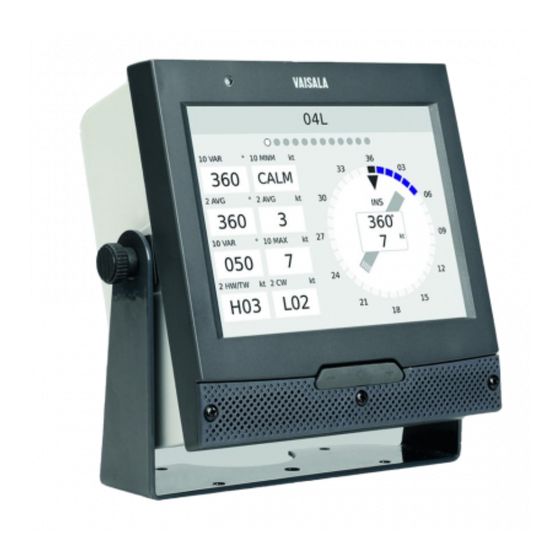
2.1 Introduction to Vaisala Panel Display Vaisala AviMet Wind Panel Display WID511 is designed for viewing real-time measurements from Vaisala wind sensors in aviation applications, in accordance with the latest ICAO standards and recommendations. The wind data pages have been designed for operative use, such as air traffic towers, and contain a wind rose and wind data fields in alphanumeric format from one sensor site. -
Page 12: Safety
2.2.1 ESD protection Electrostatic Discharge (ESD) can damage electronic circuits. Vaisala products are adequately protected against ESD for their intended use. However, it is possible to damage the product by delivering electrostatic discharges when touching, removing, or inserting any objects in the equipment housing. -
Page 13: Regulatory Compliance
Chapter 2 – Product overview More information ‣ Installation safety (page 14) 2.3 Regulatory compliance This product complies with the following regulations: • Low Voltage Directive (2014/35/EU) • EMC Directive (2014/30/EU) • RoHS Directive (2011/65/EU) • European Union CE mark • Great Britain UKCA mark •... -
Page 14: Functional Description
More information ‣ Introduction to advanced settings (page 53) 3.2 Data sources The display supports Vaisala wind sensors (such as WMT700) and multiple message formats. Figure 1 WID511 as part of system The following figures show the data flow options of WID511. -
Page 15: Interfaces
‣ Selecting messages in use (page 67) 3.3 Interfaces The display has the following customer interfaces behind the back cover: • RS‑485/RS‑422/RS‑232 ports for serial connection: The default interfaces for Vaisala sensors. • Ethernet port: If configured, an alternative interface for receiving data from an external sending unit. -
Page 16: Installation
WID511 User Guide M211109EN-L 4. Installation 4.1 Installation overview To install the display, perform the following procedures in the order presented: Selecting location (page 15) Unpacking (page 17) Removing covers (page 18) Connecting cables and grounding (page 20) Installing display (page 25) Powering (page 28) Verification (page 28) Calibration (page 28) -
Page 17: Selecting Location
Chapter 4 – Installation 4.3 Selecting location 4.3.1 Dimensions The dimensions of the display comply with the IEC 61554 and DIN 43700 standards. Figure 4 Display dimensions... -
Page 18: Required Panel Thickness
WID511 User Guide M211109EN-L 4.3.2 Required panel thickness The display can be mounted to 138 × 138 mm (5.43 × 5.43 in) panel openings. When installing several displays to a panel side by side, the minimum distance between two displays is 6 mm (0.24 in). Figure 5 Requirements for panel thickness 4.3.3 Viewing angle The viewing angle for the display:... -
Page 19: Unpacking
Before leaving the factory, the product has been thoroughly tested and found to be in perfect operating condition. However, it is recommended that you check the following: • Delivered contents are undamaged. • There are no loose screws or contacts. If necessary, report possible damages to Vaisala and tighten loose screws or contacts. -
Page 20: Removing Covers
WID511 User Guide M211109EN-L 4.5 Removing covers 1. Loosen the fixing screws for the front cover and remove the front cover. - Page 21 Chapter 4 – Installation 2. Loosen the fixing screws for the back cover and remove the back cover. Back cover fixing screws Strain relief cover plate fixing screw Removing the back cover exposes ESD sensitive components. More information ‣ Installation safety (page 14)
-
Page 22: Connecting Cables And Grounding
WID511 User Guide M211109EN-L 4.6 Connecting cables and grounding In standard delivery you need to connect only the serial or Ethernet cable and the power cable. The Ethernet cable must be a pair cable with shield grounding (Ethernet FTP CAT5). WARNING! Make sure that you prepare or connect only de-energized wires. -
Page 23: Figure 7 Display Wiring Diagram
Chapter 4 – Installation RS-422/ RS-485 RS-485 2-wire RS-232 T−/RxD 4-wire R−/TxD +12 V T−/RxD R−/TxD Figure 7 Display wiring diagram COM2 DIP switches for COM1 and COM2 Ethernet LED Ethernet USB 1 top (not in use) USB 2 bottom (not in use) COM1 Power COM0... - Page 24 WID511 User Guide M211109EN-L The display has an always active AC termination for RS‑422/RS‑485. The AC terminator contains a 160 Ω resistor and a series capacitor. 1. Remove the connectors from the circuit board. 2. Depending on the communication mode, connect the serial cable or the Ethernet cable. 3.
-
Page 25: Figure 8 Strain Relief Brackets For Connection Cables
Chapter 4 – Installation 6. Attach the cables to the strain relief brackets. If you are using the connector plate, the following figure does not apply. Figure 8 Strain relief brackets for connection cables Strain relief brackets Grounding point for the display... -
Page 26: Connector Plate (Optional)
WID511 User Guide M211109EN-L CAUTION! For proper grounding, make sure that the cable shield is between the bracket and the device. 7. Use the grounding point in the strain relief plate for equipotential bonding, where applicable. 8. Reattach the strain relief cover plate. 9. -
Page 27: Installing Display
If the display is delivered with the optional connector plate, the DIP switches are set to the RS‑485 2‑wire mode already at the Vaisala factory. If you install the connector plate after the delivery, set the DIP switches to the RS‑485 2‑wire mode yourself. -
Page 28: Mounting Display On Display Stand
WID511 User Guide M211109EN-L More information ‣ Mounting display on display stand (page 26) ‣ Mounting display as panel display (page 27) 4.7.1 Mounting display on display stand Figure 10 Display installed with display stand (showing also panel mounting brackets/screws) Panel mounting bracket Knurled thumb screw for the display stand Protective film to be removed after... -
Page 29: Mounting Display As Panel Display
Chapter 4 – Installation 6. Remove the protective film before taking the display into use. The display is now mounted on the display stand. 4.7.2 Mounting display as panel display After connecting cables and reattaching the connectors: 1. Reattach the back cover and tighten the screws that hold the cover. 2. -
Page 30: Powering
WID511 User Guide M211109EN-L 4. Reattach the front cover and tighten the fixing screws for the cover. 5. Remove the protective film before taking the display into use. See Figure 10 (page 26). The display has now been mounted as a panel display. 4.8 Powering After all the installation steps, connect the power source. -
Page 31: Operation
Chapter 5 – Operation 5. Operation 5.1 Getting started As soon as the display is powered, the screen lights up and the display starts to collect, process, and show data according to the preset configuration and user operation. The average data fields show data when enough data has been collected. If the display does not seem to start, see Possible problem situations (page 83). -
Page 32: Day And Night Display Modes
WID511 User Guide M211109EN-L • Navigation mode for navigating between data pages, viewing alarms, toggling between day/night color scheme, and entering the Maintenance mode. • Maintenance mode for accessing the basic settings, such as volume level, and advanced settings, such as managing configuration files. 5.4 Day and night display modes The display provides the day and night color schemes for different lighting conditions. -
Page 33: Entering And Exiting Observation Mode
Chapter 5 – Operation 5.5.1 Entering and exiting observation mode Observation mode is the default mode for the display. The pre-configured first data page is displayed when the system is powered up. To enter Observation mode from other modes, press Home. To exit Observation mode, touch anywhere on the screen. - Page 34 WID511 User Guide M211109EN-L • 10‑minute minimum wind speed and wind direction • 2‑minute average wind speed and wind direction • 10‑minute maximum wind speed and wind direction 5.5.4.1 Wind speed details • Displayed without the preceding zero, for example, 8. •...
-
Page 35: Display Layout Options
Chapter 5 – Operation Values are displayed in magnetic north direction. For correct functioning of the wind direction data, the wind sensor alignment and station declination must have been configured correctly. 5.5.5 Display layout options The display provides 3 different layouts for data: ATC, GEN, and ALL. To select which layouts and pages are shown, select Advanced settings >... -
Page 36: Figure 14 Example Of Atc Layout With Wd50 2-Minute Icao Data Setting
WID511 User Guide M211109EN-L Figure 14 Example of ATC layout with WD50 2‑minute ICAO data setting Table 3 ATC layout components Element Description Row 1 10‑minute wind direction variation starting point and wind speed minimum Row 2 2‑minute average wind direction and speed Row 3 10‑minute wind direction variation end point and wind speed maximum Row 4... -
Page 37: Figure 15 Gen Layout
Chapter 5 – Operation 5.5.5.2 GEN layout The GEN layout is designed for more generic use: it contains instant, 2‑minute, and 10‑minute averages and extremes. Figure 15 GEN layout Table 4 GEN layout components Element Description 2‑minute and 10‑minute blocks Row 1 Wind direction and speed average Row 2 Wind speed minimum and maximum Row 3... -
Page 38: Figure 16 All Layout
WID511 User Guide M211109EN-L 5.5.5.3 ALL layout The ALL layout is designed for more generic use at airports: it contains instant, 2‑minute, and 10‑minute averages and extremes, as well as the crosswind/headwind components. Figure 16 ALL layout Table 5 ALL layout components Element Description 2‑minute and 10‑minute blocks Row 1... -
Page 39: Using Navigation Mode
Chapter 5 – Operation 5.6 Using Navigation mode The Navigation mode allows you to: • Navigate between the available data pages • Enter the Maintenance mode • Toggle between day and night display modes • View alarms The Navigation mode is displayed on top of the Observation mode data page. Figure 17 Example of Navigation mode Table 6 Navigation mode buttons Button... -
Page 40: Entering And Exiting Navigation Mode
WID511 User Guide M211109EN-L More information ‣ Entering and exiting Navigation mode (page 38) ‣ Showing alarms (page 39) ‣ Acknowledging alarms (page 41) ‣ Alarm sound (page 41) ‣ Entering Maintenance mode (basic settings) (page 43) ‣ Entering Maintenance mode (advanced settings) (page 53) 5.6.1 Entering and exiting Navigation mode To enter Navigation mode from the Observation mode, touch anywhere on the screen. -
Page 41: Showing Alarms
Chapter 5 – Operation 2. Press Figure 18 Example with day color scheme (on left) and night color scheme (on right) 5.6.4 Showing alarms When new alarms exist, the Navigation mode shows the Alarms icon in red on top of the Observation mode:... -
Page 42: Figure 19 Example List Of Alarms
WID511 User Guide M211109EN-L Press Alarms to view a list of alarms. Figure 19 Example list of alarms After visiting the Alarms page, the Alarms icon turns grey. Depending on the alarm types, the unacknowledged alarms are marked with a red icon (alarm) or an orange icon (warning). -
Page 43: Acknowledging Alarms
Chapter 5 – Operation To see the details of an alarm, press the alarm name on the list: Figure 20 Alarm details page More information ‣ Acknowledging alarms (page 41) ‣ Error messages (page 87) 5.6.5 Acknowledging alarms On the Alarm details page, you can acknowledge the alarm or information message by pressing Acknowledge. - Page 44 WID511 User Guide M211109EN-L More information ‣ Adjusting volume (page 44)
-
Page 45: Basic Settings In Maintenance Mode
Chapter 6 – Basic settings in Maintenance mode 6. Basic settings in Maintenance mode 6.1 Entering Maintenance mode (basic settings) To enter the Maintenance mode from the Navigation mode, press Menu. The Settings page opens. Figure 21 Maintenance mode (Settings page) Table 7 Settings page buttons Button Description Audio... -
Page 46: Exiting Maintenance Mode (Basic Settings)
WID511 User Guide M211109EN-L Button Description Advanced Opens the Advanced settings page. To access the advanced settings, you need to log in with the maintenance password. Alerts Opens the Alerts page for setting the alert limit values. About Displays information about the display, for example, serial number, software version, and software license information. -
Page 47: Adjusting Brightness Using Touch Screen
Chapter 6 – Basic settings in Maintenance mode 3. On the Audio settings page, increase or decrease the volume: • To increase volume, press +. • To decrease volume, press −. The lowest volume setting available is the 1 % level. 4. - Page 48 WID511 User Guide M211109EN-L 2. On the Display settings page, increase or decrease the brightness as required: • To increase brightness, press +. • To decrease brightness, press −. You can also adjust brightness using the keys in the front panel of the display. More information ‣...
-
Page 49: Adjusting Brightness Using Front Panel Keys
Chapter 6 – Basic settings in Maintenance mode 6.5 Adjusting brightness using front panel keys To adjust the display brightness, use the brightness control keys in the front panel. Figure 22 Brightness control keys 1. Select one of the following: • To increase brightness, press the + key. •... -
Page 50: Cleaning Screen
WID511 User Guide M211109EN-L 6.6 Cleaning screen Before cleaning the screen surface, you must temporarily deactivate the touch screen. 1. On a data page, touch the screen to enter Navigation mode. 2. On the Display settings page, press Wipe. The screen is deactivated for 30 seconds. Wait for the counter to show the remaining cleaning time. -
Page 51: Changing Units
Chapter 6 – Basic settings in Maintenance mode The touch screen has been calibrated to the position accuracy of less than 1 mm. If required, you can recalibrate the touch screen. 1. On a data page, touch the screen to enter Navigation mode. 2. -
Page 52: Setting Wind Speed Alert Limits
WID511 User Guide M211109EN-L 3. On the Unit settings page, select the unit and resolution for wind speed data. 4. To save the changes, press Apply. The changes are valid only after pressing Apply. To view the data page with the new units, press Home. 6.9 Setting wind speed alert limits To display visual wind speed alerts on the data page, set the alert limits. - Page 53 Chapter 6 – Basic settings in Maintenance mode 3. On the Alerts page, select the wind speed calculation and type the alarm and warning limits. 2‑min avg 2‑minute average wind speed. 10‑min avg 10‑minute average wind speed. 10‑min max 10‑minute maximum wind speed. Tailwind 2‑minute tailwind/headwind speed.
-
Page 54: Viewing Software And License Information
WID511 User Guide M211109EN-L 6.10 Viewing software and license information 1. On a data page, touch the screen to enter Navigation mode. 2. Press Menu > About. The About page displays information about the display, for example, the serial number and the software version. 3. -
Page 55: Advanced Settings In Maintenance Mode
Chapter 7 – Advanced settings in Maintenance mode 7. Advanced settings in Maintenance mode 7.1 Introduction to advanced settings With the advanced settings, you change the configuration parameters, for example communication settings. The changes are saved in the configuration file that is located in the display memory. - Page 56 WID511 User Guide M211109EN-L 3. On the login page for the advanced settings, type the following PIN with the typing pad: 8247. 4. Press OK. The Advanced settings page opens.
-
Page 57: Exiting Maintenance Mode (Advanced Settings)
USB Flash memory stick to the display. SW Update Displays the current software version. For Vaisala use only: Allows upgrading to a newer software version to the display using USB Flash memory. Page selection Opens the page for selecting which of the available data pages are displayed. -
Page 58: Using Typing Pad
WID511 User Guide M211109EN-L After making changes on the settings pages, always press Apply to save the changes. 7.5 Using typing pad On some of the settings pages, you need to use a typing pad to enter data. The typing pad opens when you press an editable data field on a settings page: •... -
Page 59: Exporting Configuration Files To Usb Flash Memory
Chapter 7 – Advanced settings in Maintenance mode Using the advanced settings in the Maintenance mode, you can change the configuration parameters, for example communication settings. The changes are saved in the configuration file that is located in the display memory. You can copy the configuration for backup purposes, or download the configuration from one display to another, by using the USB Flash memory stick. - Page 60 WID511 User Guide M211109EN-L 1. To insert the USB Flash memory into the display, remove the front cover of the display. a. Loosen the fixing screws for the front cover. b. Remove the front cover. 2. Enter Maintenance mode. 3. On the Advanced settings page, press Configurations.
- Page 61 SD card interface (not in use) USB port for exporting and importing configuration files with USB Flash memory USB port for computers (for Vaisala use only) 5. Press Refresh. The Configurations page displays a list of the configurations available in the USB Flash memory.
-
Page 62: Importing Configuration Files From Usb Flash Memory
WID511 User Guide M211109EN-L 8. Reattach the front cover of the display and tighten the fixing screws for the cover. More information ‣ Interfaces (page 13) ‣ Editing configuration files (page 56) 7.8 Importing configuration files from USB Flash memory You can import a configuration file from a USB Flash memory to a display to replace the existing configuration. - Page 63 Chapter 7 – Advanced settings in Maintenance mode 1. To insert the USB Flash memory into the display, remove the front cover of the display. a. Loosen the fixing screws for the front cover. b. Remove the front cover. 2. Enter Maintenance mode. 3.
- Page 64 SD card interface (not in use) USB port for exporting and importing configuration files with USB Flash memory USB port for computers (for Vaisala use only) 5. The Configurations page displays a list of the available configurations in the USB stick.
-
Page 65: Viewing Network Information
‣ Editing configuration files (page 56) 7.9 Viewing network information By default, the display retrieves the IP address and other network configuration data automatically using DHCP. It is also possible to order the display from Vaisala with a specific network configuration. 1. Enter Maintenance mode. -
Page 66: Changing Network Address
WID511 User Guide M211109EN-L 2. On the Advanced settings page, press Network. The Network settings page displays the network addresses. 7.10 Changing network address 1. Enter Maintenance mode. 2. On the Advanced settings page, press Network. 3. If DHCP addressing is in use, press Switch to static. 4. - Page 67 Chapter 7 – Advanced settings in Maintenance mode 5. On the Change network settings page, press a data field to open the typing pad. 6. Type in the needed numbers and characters and press OK. 7. To save the changes, press Apply. To cancel the changes, press Back.
-
Page 68: Switching Between Dhcp And Static Addressing
WID511 User Guide M211109EN-L 7.11 Switching between DHCP and static addressing 1. Enter Maintenance mode. 2. On the Advanced settings page, press Network. 3. On the Network settings page, press Switch to DHCP or Switch to static. 7.12 Viewing network status 1. Enter Maintenance mode. 2. -
Page 69: Selecting Messages In Use
Chapter 7 – Advanced settings in Maintenance mode 3. In Page selection, select the page or pages that you want to display. 4. To save the changes, press Apply. At least one page has to be selected. Apply is disabled if no pages are selected. 7.14 Selecting messages in use You can select which messages the display receives from the sensor. -
Page 70: Configuring Message And Communication Settings
WID511 User Guide M211109EN-L 3. On the Select messages in use page, select the messages that are used in the system. CAUTION! Make sure that all the needed messages are selected. If a message is not selected, the data from the message is not displayed on the data pages and the alerts for missing data are NOT displayed. - Page 71 Chapter 7 – Advanced settings in Maintenance mode 4. On the Message settings page, select the message from the list on the left. The current settings are displayed on the right. 5. To edit the settings for the selected message, press Change.
- Page 72 WID511 User Guide M211109EN-L 6. On the message settings, depending on the data type: • Press the arrow to open the list and select from the list of options. • Press the data field to open the typing pad. When finished, press OK. Interface Select the communication interface used for receiving data from the sensor, for example, COM2 if serial connection is used.
-
Page 73: Configuring Com Port Settings
Chapter 7 – Advanced settings in Maintenance mode (Wind sensor only) Select True north or Magnetic north depending on the actual alignment of the wind sensor. See also Configuring station settings (page 79). Sensor ID Type the ID of the sensor, when applicable. In the poll mode, the ID must be defined and must match the ID in the sensor. - Page 74 WID511 User Guide M211109EN-L 3. On the COM port settings page, select the COM port from the list on the left, if available. The current settings are displayed on the right. 4. To edit the settings of the selected COM port, press Change.
- Page 75 Chapter 7 – Advanced settings in Maintenance mode 5. In the COM port settings, depending on the data type: • Press the arrow to open the list and select from the list of options. • Press the data field to open the typing pad. When finished, press OK. Connection type Select the RS connection type from the available options, for example, RS‑485 2‑w for 2‑wire RS‑485.
-
Page 76: Viewing Incoming Data In Com Port
WID511 User Guide M211109EN-L More information ‣ Connecting WMT700 (page 95) 7.17 Viewing incoming data in COM port On the terminal page, you can view the incoming data in the selected COM port. 1. Enter Maintenance mode. 2. On the Advanced settings page, press COM. 3. -
Page 77: Configuring Net Connection Settings
Chapter 7 – Advanced settings in Maintenance mode 5. On the terminal page, you can see all the incoming messages in the selected COM port. When the terminal page is open, normal communication between the display and the sensor stops. In the autosend mode, the display stops processing the messages coming through the selected COM port. - Page 78 WID511 User Guide M211109EN-L 3. On the Net connection settings page, select the NET connection port from the list on the left. The current settings are displayed on the right. 4. To edit the settings of the selected NET port, press Change.
- Page 79 Chapter 7 – Advanced settings in Maintenance mode 5. In the NET settings, depending on the data type: • Press the arrow to open the list and select from the list of options. • Press the data field to open the typing pad. When finished, press OK. Connection type UDP, TCP server, or TCP client.
-
Page 80: Viewing Incoming Data In Net Port
WID511 User Guide M211109EN-L 6. To save the changes, press Apply. The changes are valid only after pressing Apply. 7.19 Viewing incoming data in NET port On the terminal page, you can view the incoming data in the selected NET port. 1. -
Page 81: Configuring Station Settings
Chapter 7 – Advanced settings in Maintenance mode 5. On the terminal page, you can see all the incoming messages in the selected NET port. When the terminal page is open, normal communication between the display and the sensor stops. In the autosend mode, the display stops processing the messages coming through the selected NET port. -
Page 82: Selecting Data Display Setting (Atc)
WID511 User Guide M211109EN-L 3. On the Station settings page, to change the settings, press the data fields, and use the typing pad to type the new setting. Declination (deg, - for west) In degrees, use the – character to indicate west, for example - 10. 4. -
Page 83: Setting Time
Chapter 7 – Advanced settings in Maintenance mode 3. On the Data settings page, select how to display the data values on the ATC page. Normal The ATC page displays all the data values. This is the default setting. WD50 2‑min ICAO The ATC page presentation is similar to WIND50 display 2‑minute page with ICAO mode ON. - Page 84 WID511 User Guide M211109EN-L 2. On the Advanced settings page, press Time settings. 3. On the Time settings page, select which option to use: • To configure date and time manually, press the related button and type in the date and time information using the typing pad.
-
Page 85: Troubleshooting
Power supply or the display may be faulty. Check the power supply and replace it when needed. If the power supply is OK, the display may have a hardware failure. Contact Vaisala. Text “Starting..” is constantly displayed Probable cause Solution The display may be faulty (system failure). - Page 86 Display logo is constantly displayed Probable cause Solution The display may be faulty (application failure). Contact Vaisala with details of the phase where the problem occurred. Slash marks (///) are displayed in data fields instead of data Probable cause Solution The system has just started and not enough data has Wait for 10 minutes.
- Page 87 Chapter 8 – Troubleshooting Alarms cannot be heard Probable cause Solution Volume may be muted. Adjust volume level. There is no navigation indicator on the data page Probable cause Solution There is only one page available. If more pages should be available, check the site settings.
-
Page 88: Led Indicators
WID511 User Guide M211109EN-L 8.3 LED indicators If the front cover has been removed, the following LED indicators can be seen during device power‑up. When the application starts, the LEDs turn off automatically. Figure 24 LED indicators (during power-up) behind front cover Red LED: Heartbeat, blinks when the operating system is running Yellow LED: Flash memory activity The LED indicators for the Ethernet connection are located behind the back cover. -
Page 89: Error Messages
Chapter 8 – Troubleshooting Description Both LEDs are lit Ethernet connection is not working, or the cable is not connected. 8.4 Error messages To view the list of alarms, press Alarms. To view further information of a specific alarm, select an alarm on the screen. The Device and Site fields show which sensor and site the alarms concern. -
Page 90: Technical Data
WID511 User Guide M211109EN-L 9. Technical data 9.1 Specifications Table 11 Operating environment Property Description/Value Operating temperature 0 … +40 °C (+32 … +104 °F) Storage temperature −20 … +80 °C (−4 … +176 °F) Operating humidity 2 … 95 %RH, non-condensing IP rating IP20 Flammability class UL94 V‑0... -
Page 91: Table 15 Mechanical Specifications
Chapter 9 – Technical data Property Description/Value Compliance marks CE, UKCA, RCM Drop test compatibility MIL‑STD‑810G 516.6 Procedure IV, Free Fall (Rough Handling) Vibration compatibility MIL‑STD‑810G 514.6C‑3 Procedure I, Cargo Vibration Test EMC compatibility IEC/EN/BS 61326‑1, industrial environment EMC emissions CISPR 32 / EN/BS 55032, Class B Table 15 Mechanical specifications Property... -
Page 92: Appendix A: Message Formats
WID511 User Guide M211109EN-L Appendix A. Message formats A.1 Wind message formats More information ‣ Configuring message and communication settings (page 68) ‣ MWV message format (page 90) ‣ WMT700 data message 24 (page 91) ‣ WAT11 message (page 92) A.1.1 MWV message format The variable-length comma separated MWV as defined by NMEA 0183 can be used to receive wind data. -
Page 93: Wmt700 Data Message 24
In the display you can use wildcards (**) as the ID. When sensor ID is needed (for example, in polling) , Vaisala sensors use “P” + 1 character between A and Z. Example or MWV message $WIMWV,320,R,15.0,M,A*0B<CR><LF>... -
Page 94: Wat11 Message
WID511 User Guide M211109EN-L Name Description Wind direction, average Wind speed, maximum Wind speed, minimum Sonic temperature Heater voltage Supply voltage Transducer temperature Status code. The code is a decimal number. Each bit corresponds to a status flag. Checksum calculation end point, not shown in the message Print checksum (to verify message integrity) WMT700 data message 24 does not include a device ID and therefore does not support polling. - Page 95 Appendix A – Message formats Name Description <STX> ASCII character, Start of text, #002 <ID> Sensor/message ID: 1 character, A ... Z <spd> Wind speed (in meters per second) multiplied by 10. For example, 045 is 4.5 meters per second (3 digits) <dir>...
-
Page 96: Appendix B: Sensor Wiring
WID511 User Guide M211109EN-L Appendix B. Sensor Wiring B.1 Connecting sensor to display To create a 2‑wire RS‑485 connection to a sensor, use the COM2 or COM1 R− and R+ connectors. For the wiring diagram and jumper settings, see Connecting cables and grounding (page 20). -
Page 97: Connecting Wmt700
Appendix B – Sensor Wiring B.2 Connecting WMT700 Create a 2‑wire RS‑485 connection from the display to WMT700. Figure 26 WMT700 cable wiring 1. Connect the display COM1 or COM2 R− to WMT700 COM2 RS‑485− signals in pins 3 and 4. 2. Connect the display COM1 or COM2 R+ to WMT700 COM2 RS‑485+ signals in pins 14 and 15. -
Page 99: Warranty
Conditions of Sale for details of the warranty for each product. Technical support Contact Vaisala technical support at helpdesk@vaisala.com. Provide at least the following supporting information as applicable: • Product name, model, and serial number •... - Page 102 www.vaisala.com...
Need help?
Do you have a question about the AviMet WID511 and is the answer not in the manual?
Questions and answers