Table of Contents
Advertisement
Quick Links
Advertisement
Table of Contents
Troubleshooting

Related Manuals for Vaisala AWS330


Summary of Contents for Vaisala AWS330
- Page 1 USER'S GUIDE Vaisala Automatic Weather Station AWS330 M211296EN-A...
- Page 2 The contents are subject to change without prior notice. Please observe that this manual does not create any legally binding obligations for Vaisala towards the customer or end user. All legally binding commitments and agreements are included exclusively in the applicable supply contract or Conditions of...
-
Page 5: Table Of Contents
Trademarks ................12 License Agreement ..............12 Redistribution License Agreement........13 Warranty.................. 14 CHAPTER 2 PRODUCT OVERVIEW................15 Introduction to AWS330............15 Product Nomenclature............18 CHAPTER 3 FUNCTIONAL DESCRIPTION..............19 Operating Principles .............. 19 Sensor Reading ..............21 Observation Values..............22 Air Temperature and Relative Humidity ...... - Page 6 User's Guide ______________________________________________________________________ CHAPTER 4 INSTALLATION....................31 Necessary Equipment ............31 Requirements for Software Configuration......32 Selecting Location..............33 Ambient Measurements ............33 Tilt Direction of the Mast............34 Soil Evaluation for the Mast..........34 Site Preparation ..............35 Power Supply and Communication Lines ......35 Equipment Grounding and Lightning Protection ....36 Foundation ................39 Soil and Frost Conditions ............39 Orientation of the Mast ............39...
-
Page 7: Vaisala
Powering Up the System ............99 CHAPTER 5 SOFTWARE CONFIGURATION AND OPERATION ........ 101 Software Installation ............101 Connecting AWS Client to AWS330 ........102 Installing USB Driver ............102 Connecting to AWS330............. 103 General Instructions on Using AWS Client ....... 104 Starting and Exiting AWS Client........ - Page 8 User's Guide ______________________________________________________________________ Station Parameter Backup and Restore......151 Working with Data Log Files..........153 Downloading Log Files ..........154 Converting Downloaded Log Files to CSV Format ..156 Using External Memory Card ..........160 Automatic Erase from External Memory Card....161 Resetting the QML Logger...........162 Operating Local LCD Display QMD202 ......163 CHAPTER 6 MAINTENANCE..................165...
- Page 9 Updating AWS330 Configuration File ....... 199 Updating Software to the Logger ........201 Copying New AWS330 Software with Loader Program ............... 201 Copying a New AWS330 Software from CF Memory Card ................203 CHAPTER 7 TROUBLESHOOTING ................205 Troubleshooting QML Logger QML201C ......205 Opening a Service Connection through QML Logger..
- Page 10 User's Guide ______________________________________________________________________ Technical Support ..............234 Vaisala Service Centers ............234 Product Returns..............234 Requesting RMA..............235 CHAPTER 8 TECHNICAL DATA ..................237 Wiring..................237 QML Logger QML201C .............237 Communication Modules...........240 Dual RS-485 Module DSI486 ........240 Digital I/O Module QMI118 ...........243 Ethernet Communication Module DSE101 ....245 Specifications ...............246...
- Page 11 ________________________________________________________________________________ APPENDIX A WIRING DIAGRAMS .................. 263 AWS330 System Basic Wiring Diagrams ......263 APPENDIX B CALCULATION FORMULAS ..............273 Dewpoint Temperature ............273 Heat Index ................274 Wind Chill (NWS 2001) ............275 Wet Bulb Temperature ............275 QFE/QFF Pressure ............... 278 QNH Pressure ...............
- Page 12 User's Guide ______________________________________________________________________ This page intentionally left blank. 8 ___________________________________________________________________ M211296EN-A...
-
Page 13: Chapter 1 General Information
- Chapter 6, Maintenance, provides information that is needed in the basic maintenance of AWS330. - Chapter 7, Troubleshooting, describes common problems, their probable causes and remedies, and provides contact information for technical support. - Chapter 8, Technical Data, provides the technical data of AWS330. VAISALA ________________________________________________________________________ 9... -
Page 14: Version Information
Related Manuals The related manuals are contained on your installation CD. It is recommended that you refer to this User's Guide as your primary source of information on AWS330. Documentation Conventions Throughout the manual, important safety considerations are highlighted as follows: WARNING Warning alerts you to a serious hazard. -
Page 15: Product-Related Safety Precautions
Chapter 1 ________________________________________________________ General Information Product-Related Safety Precautions The Vaisala Automatic Weather Station AWS330 delivered to you has been tested for safety and approved as shipped from the factory. Note the following precautions: All electrical installations must be carried by licensed experts as WARNING governed by local and state authorities, legislation, and regulations. -
Page 16: Recycling
United States and/or other countries. License Agreement All rights to any software are held by Vaisala or third parties. The customer is allowed to use the software only to the extent that is provided by the applicable supply contract or Software License Agreement. -
Page 17: Redistribution License Agreement
HOWEVER CAUSED AND ON ANY THEORY OF LIABILITY, WHETHER IN CONTRACT, STRICT LIABILITY, OR TORT (INCLUDING NEGLIGENCE OR OTHERWISE) ARISING IN ANY WAY OUT OF THE USE OF THIS SOFTWARE, EVEN IF ADVISED OF THE POSSIBILITY OF SUCH DAMAGE. VAISALA _______________________________________________________________________ 13... -
Page 18: Warranty
User's Guide ______________________________________________________________________ Warranty For certain products Vaisala normally gives a limited one-year warranty. Visit our Internet pages for more information and our standard warranty terms and conditions: www.vaisala.com/services/warranty.html. Please observe that any such warranty may not be valid in case of damage due to normal wear and tear, exceptional operating conditions, negligent handling or installation, or unauthorized modifications. -
Page 19: Chapter 2 Product Overview
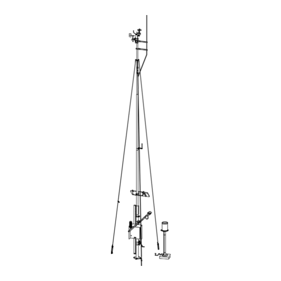
By using the optional Observation Display software, data can be saved onto a PC and presented in visual format. Vaisala offers a variety of services related to AWS330, including site survey, installation, high-quality sensor calibration (including ISO/IEC 17025-accredited) calibration, and extended warranty. Contact Vaisala for more details and an up-to-date listing of the current offering;... - Page 20 User's Guide ______________________________________________________________________ The following numbers refer to Figure 1 on page 17: 1 = Ultrasonic Wind Sensor WMT703 2 = Mechanical Wind Sensor Set WA15 3 = Lightning rod 4 = Guy wire 5 = GSM/GPRS antenna 6 = Mast 7 = Air Temperature and Relative Humidity Probe HMP155 and Radiation Shield DTR503A 8 = Solar Panel SOLAR33...
- Page 21 Ultrasonic Wind Sensor WMT703 and Mechanical Wind Sensor Set WA15 (numbers 1 and 2 in Figure 1 above) are used as alternatives to each other for measuring wind speed and direction. In addition, AWS330 can feature one or two QMT110 soil temperature sensors.
-
Page 22: Product Nomenclature
User's Guide ______________________________________________________________________ Product Nomenclature Table 2 Vaisala Automatic Weather Station AWS330 Nomenclature Code Common Name DKP210 Mast DKP12SUP Sensor support HMP155 Air temperature and relative humidity probe DTR503A Radiation shield for HMP155 RG13(H) Rain gauge (with heating) RGSTAND1140 Rain gauge stand... -
Page 23: Functional Description
Chapter 3 ______________________________________________________ Functional Description CHAPTER 3 FUNCTIONAL DESCRIPTION This section describes the operating principles of AWS330. Operating Principles Sensors are measured by AWS330 system as: - Voltage or resistance input converted to measurement value by analog to digital conversion. For example, Pt100 temperature. - Page 24 User's Guide ______________________________________________________________________ Figure 2 below illustrates the general AWS330 application functionality with full sensor configuration. 1011-012 Figure 2 Functional Diagram of AWS330 Application 20 __________________________________________________________________ M211296EN-A...
-
Page 25: Sensor Reading
Chapter 3 ______________________________________________________ Functional Description Sensor Reading Reading frequencies for AWS330 sensors are listed in Table 3 below. Table 3 Sensor Reading Frequencies Sensor Output Frequency (s) HMP155 Temperature HMP155 Humidity BARO-1 Barometric pressure WMT703 Wind speed WMT703 Wind direction... -
Page 26: Observation Values
User's Guide ______________________________________________________________________ Observation Values Depending on the selected sensor configuration, the AWS330 system produces various statistical and derived meteorological outputs. The following tables list outputs by category. Values with 1 minute or shorter period are regarded as instant values, that is, they are averaged from several samples. -
Page 27: Atmospheric Pressure/Vapor Pressure
Decreasing, then steady, or decreasing, then lower than 3 hours decreasing more slowly. ago. Decreasing steadily or unsteadily. Steady or increasing, then decreasing; or decreasing, then decreasing more rapidly. See section QFE/QFF Pressure on page 278 for pressure calculation formulas. VAISALA _______________________________________________________________________ 23... -
Page 28: Wind
User's Guide ______________________________________________________________________ Wind The wind calculation method is scalar. See section Wind Calculation Formulas on page 280 for wind calculation formulas. Table 6 Products for Wind Reported Parameter Unit Statistic Period Interval Message Tag Direction degrees Average 1 sec Speed Average 1 sec... -
Page 29: Soil/Water Temperature
See section Evapotranspiration on page 285 for evapotranspiration formula. System Status Table 11 System Status Indicator Reported Parameter Unit Statistic Period Interval Message Tag System uptime 1 min UPTIME Data logger status STATUS Power supply voltage 1 min EXTDC VAISALA _______________________________________________________________________ 25... -
Page 30: Alarms
User's Guide ______________________________________________________________________ Alarms AWS330 system can be enabled to send alarm messages based on selected observation values and technical alarms based on system and sensor status. The following alarm sources and limits are available: Table 12 Alarm Sources and Types... -
Page 31: Message Formats
TAAVG1M:-0.3; Tags for observation values are listed in section Observation Values on page 22. Missing observation values are replaced with one or more slash '/' characters. Example of a full CSV Message is shown on page 289. VAISALA _______________________________________________________________________ 27... -
Page 32: Table
User's Guide ______________________________________________________________________ Table Table message is a message in readable format with instant values and sensor status values. The following values are displayed in the table message: Table 13 Table Message Values Row Label/Column Instant Average Status Station name Station name Date Date time UTC... -
Page 33: Sms
= Separator character between fields = Separator character between tag and value Example tag/value pair with trailing separator: TA:-10.3; Missing observation values are replaced with a single slash '/' character. See example SMS Message on page 290. VAISALA _______________________________________________________________________ 29... -
Page 34: Alarm Messages
IRU9429 Snow height sensor failure Example sensor alarm message: (S:AWS330;D:101209;T:091600;ALARM:Humidity sensor failure) Sensor failure alarms can be sent as above or as an attachment to table message. For an example, see section Table Message with Alarm List on page 291. -
Page 35: Chapter 4 Installation
Chapter 4 _______________________________________________________________ Installation CHAPTER 4 INSTALLATION This chapter provides you with information that is intended to help you install AWS330. The individual sensors may come with their own instructions. However, NOTE refer to this manual for all installation instructions. -
Page 36: Requirements For Software Configuration
User's Guide ______________________________________________________________________ Requirements for Software Configuration Table 16 below lists the items and information that are required before configuring the AWS330 system. Table 16 Items/Information Required Prior to Configuration Pre-requisite Item/Information Source All sites Unique site name User-provided Barometric pressure... -
Page 37: Selecting Location
In general, there should be at least 150 m of open area to all directions from the mast. The minimum distance between the mast and obstacles is ten times the height of an obstacle. Refer to Figure 3 below. 1012-170 Figure 3 Recommended Mast Location in Open Area VAISALA _______________________________________________________________________ 33... -
Page 38: Tilt Direction Of The Mast
User's Guide ______________________________________________________________________ Tilt Direction of the Mast Also note the tilting direction of the mast. When installed in the northern hemisphere, the mast tilts to the west. There should be a clear area up to 9 m on the west side of the mast. The area should be free of obstacles preventing the mast from being erected and tilted. -
Page 39: Site Preparation
It is recommended that you use a conduit to protect the cables that connect the indoor components to the outdoor components from damage and moisture. Also traffic, standing water, and the twist and stress caused by the connectors will damage the cables. VAISALA _______________________________________________________________________ 35... -
Page 40: Equipment Grounding And Lightning Protection
User's Guide ______________________________________________________________________ Equipment Grounding and Lightning Protection WARNING Consult the local electricity professionals for the local grounding requirements. The customer is responsible for supplying grounding cables, rods, clamps, power cables, long distance signal cables, and conduits for cables. With mast installations, equipment grounding and lightning protection must be done separately. - Page 41 The following numbers refer to Figure 4 above: Lightning protection grounding rod Guy wire block of the isolated guy wire 3 Mast block Optional grounding rod Optional connecting cable 5-meter minimum distance between the rods Equipment grounding rod VAISALA _______________________________________________________________________ 37...
- Page 42 User's Guide ______________________________________________________________________ - The recommended grounding resistance is 10 Ω or less for both the grounding of lighting protection rod and for the equipment grounding. Soil conditions (sand, rocks, and so on) and the ground resistance measurement determine the design and construction of the grounding system.
-
Page 43: Foundation
To ease the orientation of the mast, the two-headed arrow is cut on the orientation plate. "N" should face north and "S" should face south to ensure the aiming of the weather station devices to the correct position. VAISALA _______________________________________________________________________ 39... - Page 44 User's Guide ______________________________________________________________________ 0207-064 Figure 5 Mast DKP210 Orientation 40 __________________________________________________________________ M211296EN-A...
-
Page 45: Concrete Foundations
For the protection of the cables, it is recommended that you install a cable conduit, which has a minimum diameter of 70 mm (2.76 in.). See Figure 6 below. 0303-026 Figure 6 Main Mast Block and Orientation Plate (Dimensions in VAISALA _______________________________________________________________________ 41... -
Page 46: Making A New Concrete Block
User's Guide ______________________________________________________________________ Concrete block dimensions for the guy wires are presented in Figure 7 below. 0303-027 Figure 7 Concrete Block for Guy Wire (Dimensions in mm) Making a New Concrete Block Make a cast mould with steel reinforcements according to the design shown in Figure 8 below. - Page 47 Foundation Assemblies for a New Concrete Block Install the foundation assembly into the mould so that the foundation bolt threads stand above the surface, see Figure 6 on page 41. The orientation plate (number 4 in Figure 10 above) VAISALA _______________________________________________________________________ 43...
-
Page 48: Using An Existing Concrete Block
User's Guide ______________________________________________________________________ should be at the same height as the top of the finalized concrete block. Protect the threads of the bolts above the orientation plate, for example, by taping them. Also check the correct alignment of the foundation assembly with the orientation plate. "N" should face north and "S"... -
Page 49: Mechanical Installation Procedure
Connecting Sensor Cables as described on page 97. Powering Up the System as described on page 99. After the mechanical installation, AWS330 is configured with a laptop PC and AWS Client software as described in Chapter 5, Software Configuration and Operation, on page 101. -
Page 50: Installing Mast Dkp210
User's Guide ______________________________________________________________________ Installing Mast DKP210 DKP210 is a 10-meter tiltable mast. The mast is designed to withstand high wind conditions, up to 50 m/s of maximum wind speed, with a standard set of guy wires. The plate of the pedestal tube is made of stainless steel with a powder coating resistant to corrosion. -
Page 51: Tools Required For Mast Installation
Chapter 4 _______________________________________________________________ Installation 1012-201 Figure 12 DKP210 Mast Dimensions (in mm) Tools Required for Mast Installation You need a set of Allen keys, two wrenches (17 and 30 mm), a spirit level, a compass, and a big hammer. VAISALA _______________________________________________________________________ 47... -
Page 52: Mast Installation Procedure
User's Guide ______________________________________________________________________ Mast Installation Procedure To assemble the mast, follow the work order below: Attach the 2-meter-high pedestal tube to the concrete foundation. Lift the first part of the mast to the upper end of the pedestal tube and assemble the hinge axle. Attach the lifting rod to the clamp preinstalled to the first part of the mast. -
Page 53: Installing The Pedestal Tube
Pedestal Tube Attachment The following numbers refer to Figure 13 above: Pole mast Nut M20 DIN934, 8 pcs; use wrench 30 mm Spring washer B20 DIN127, 8 pcs Washer A20 DIN125, 8 pcs Plate lug Guide plate, META-0501 Foundation VAISALA _______________________________________________________________________ 49... -
Page 54: Connecting The First Part Of The Mast To The Pedestal Tube
User's Guide ______________________________________________________________________ Connecting the First Part of the Mast to the Pedestal Tube To connect the first part of the mast to the pedestal tube, install the axle for the hinge. Take the axle (number 3 in Figure 14 below) from the plastic bag labeled "Hinge Set". -
Page 55: Connecting The Lifting Rod To The Mast
Lifting Rod Installation The following numbers refer to Figure 15 above: Allen bolt M8x25 DIN912 A4, 8 pcs; use Allen key 6 mm Spring washer B8 DIN127 A4, 8 pcs Lifting rod First part of the mast VAISALA _______________________________________________________________________ 51... -
Page 56: Assembling The Remaining Parts Of The Mast
User's Guide ______________________________________________________________________ Assembling the Remaining Parts of the Mast The remaining parts of the mast have an O-ring (number 1 in Figure 16 below) installed on the mast part. Just slide the parts of the mast together to connect them. You need to rotate either of the parts to align the groove (2) on the upper part and the ridge (3) inside the lower part. -
Page 57: Connecting The Guy Wires To The Mast
2 = Narrowing of the mast 3 = Guy wire 4 = Washer B8 DIN127 A4, 3 pcs 5 = Allen bolt M8x40 DIN912, 3 pcs; use Allen key 6 mm 6 = Guy wire 1 with the snap hook VAISALA _______________________________________________________________________ 53... -
Page 58: Installing The Lightning Rod
User's Guide ______________________________________________________________________ Installing the Lightning Rod To install the lightning rod, proceed as follows: Slide the lightning rod (number 1 in Figure 18 on page 55) to the holes in the lightning rod holders (2) and attach the rod to the holders using the fastening plates (6). - Page 59 After you have carefully verified the installation, tilt the mast again and start installing sensors and accessories (wind sensors, GSM/GPRS antenna, and solar panel). VAISALA _______________________________________________________________________ 55...
-
Page 60: Erecting Mast Dkp210
User's Guide ______________________________________________________________________ Erecting Mast DKP210 Before erecting the mast, check that all the parts are firmly attached. Check that the top fastener is secure on the upper end of the mast. Installing and Using the Winch It is recommended that you use the easy-to-install winch for erecting the mast. - Page 61 Wrap the clamps (1) around the tube to the clamp assemblies (4) and attach them. Finally, secure the clamps with the provided pin clips as shown in Figure 21 below. 0303-042 Figure 21 Securing Clamp of the Winch VAISALA _______________________________________________________________________ 57...
- Page 62 User's Guide ______________________________________________________________________ Attach the cable bearer to the plate lug (number 5 in Figure 13 on page 49) of the pedestal plate. Make sure that the free wire end points toward the end of the lifting rod (see correct positioning of the cable bearer in Figure 22 below).
-
Page 63: Securing The Hinge
Bolts and Washers for Securing the Hinge The following numbers refer to Figure 23 above: Allen bolt M10x30 DIN912 A4, 4 pcs; use Allen key 8 mm Spring washer B10 DIN127 A4, 4 pcs Washer A10.5 DIN125 A4, 4 pcs VAISALA _______________________________________________________________________ 59... -
Page 64: Connecting The Guy Wires To The Concrete Blocks
User's Guide ______________________________________________________________________ Connecting the Guy Wires to the Concrete Blocks For the guy wires 2 and 3, connect the U-bolt (number 4 in Figure 24 on page 61) to the eye nut (5) installed on the concrete block. Slide the strap (3) onto the U-bolt and thread the nuts. For the guy wire 1, connect the U-bolt to the eye nut with an additional bow shackle to enable easy releasing of the wire. - Page 65 2 = Wire clip 3 = Strap 4 = U-bolt 5 = Eye nut 6 = Additional bow shackle 7 = Nut M6 DIN934; use wrench 10 mm 8 = Nut M12 DIN934; use wrench 19 mm 9 = Wedge VAISALA _______________________________________________________________________ 61...
-
Page 66: Installing Ultrasonic Wind Sensor Wmt703
User's Guide ______________________________________________________________________ Installing Ultrasonic Wind Sensor WMT703 Ultrasonic Wind Sensor WMT703 measures wind speed and direction. WMT703 is installed on top of the mast with the FIX70 mounting kit. The sensor is shipped in a custom cardboard container with plastic transportation dampers. - Page 67 A lightning rod must be installed above the wind sensor; see section WARNING Equipment Grounding and Lightning Protection on page 36. WARNING Do not install WMT703 when there is a risk of thunderstorm or lightning activity in the area. VAISALA _______________________________________________________________________ 63...
-
Page 68: Mounting Wmt703
User's Guide ______________________________________________________________________ Mounting WMT703 To mount WMT703 on the mast, proceed as follows: Attach the mast adapters (numbers 2, 4, and 5 in Figure 27 on page 65, both sides) to the FIX70 mounting kit (1). Install the FIX70 mounting kit to the mast (11) with the U-bolts (7). - Page 69 8 = Spring washer B8 DIN127 A4, 4 pcs 9 = Nut M8 DIN934 A4, 4 pcs; use wrench 13 mm 10 = Fixing screw M6x10 DIN912 A4, 1 pcs; use Allen key 5 mm 11 = Mast VAISALA _______________________________________________________________________ 65...
-
Page 70: Checklist For Connection Cables
User's Guide ______________________________________________________________________ 1004-084 Figure 28 Tightening the Connector The following number refers to Figure 28 above: 1 = Tighten the connector by rotating the ribbed part of the connector by hand. Do not use tools. NOTE Verify that the connector is properly tightened to avoid water leakage and damage to the sensor. -
Page 71: Aligning Ultrasonic Wind Sensor Wmt703
Tighten the bolts of the FIX70 mounting kit. Figure 29 below and Figure 30 on page 68 show the correct alignment and the measurement error caused by misalignment of WMT703. 0208-025 Figure 29 Correctly Aligned WMT703 VAISALA _______________________________________________________________________ 67... - Page 72 User's Guide ______________________________________________________________________ 1001-018 Figure 30 Incorrectly Aligned WMT703 and the Resulting Offset Error N = The correct direction for true north a = The wind direction offset error caused by the misalignment of WMT703 68 __________________________________________________________________ M211296EN-A...
-
Page 73: Installation Tips For Aligning Wind Sensors
Use the appropriate angle meter to set the correct declination. 1012-212 Figure 31 Installing Wind Sensors The following numbers refer to Figure 31 above: 1 = Mast 2 = Tilting support 3 = Instrument (WA15) 4 = Spirit level VAISALA _______________________________________________________________________ 69... -
Page 74: Installing Mechanical Wind Sensor Set Wa15
User's Guide ______________________________________________________________________ Installing Mechanical Wind Sensor Set WA15 Mechanical Wind Sensor Set WA15 consists of a Vaisala Anemometer WAA151, a Vaisala Wind Vane WAV151, a cross arm WAC151, a junction box, and cabling. Install WA15 as follows: Attach the cross arm to the top of a pole mast with the mounting clamp. - Page 75 5 = Screw M6x16 DIN7992 A4, 6 pcs; use Allen key 4 mm (preinstalled) 6 = Washer A6.4 DIN127 A4, 4 pcs (pre-installed) 7 = Screw M6x25 DIN912 A4, 4 pcs; use Allen key 5 mm (preinstalled) VAISALA _______________________________________________________________________ 71...
-
Page 76: Installing Gsm/Gprs Antenna
User's Guide ______________________________________________________________________ Installing GSM/GPRS Antenna To install the GSM/GPRS modem, you need to mount the antenna to the mast and insert the SIM card into the modem (see section Preparing GSM/GPRS Modem on page 96). The GSM/GPRS antenna is an omnidirectional antenna. The antenna provides high gain, enabling better signal at installation sites where long distances to the base station or the terrain cause uncertain connections. -
Page 77: Installing Solar Panel Solar33
The rays of the sun should be perpendicular to the panel. In other words, sunlight should hit the panel at a 90° angle. NOTE Do not concentrate light on the panel in an attempt to increase its power output. VAISALA _______________________________________________________________________ 73... - Page 78 Secure the cable with cable ties. Do not connect the solar panel cable to the enclosure until the mechanical installation of AWS330 is complete, the backup batteries are connected, and the weather station is ready for powering; see instructions in section Powering Up the System on page 99.
- Page 79 5 = Screw M6x20 DIN912 A4, 4 pcs; use Allen key 5 mm 6 = Spring washer B6 DIN127 A4, 8 pcs 7 = Washer A6 DIN 125 A4, 4 pcs 8 = Screw M6x25 DIN912 A4, 4 pcs; use Allen key 5 mm VAISALA _______________________________________________________________________ 75...
- Page 80 User's Guide ______________________________________________________________________ 1101-012 Figure 35 Adjusting Solar Panel SOLAR33 Tilting Angle The following letter and number refer to Figure 35 above: α = Tilting angle 9 = Adjusting screws; use Allen key 5 mm and wrench 10 mm Table 18 Recommended Tilt Angle for Solar Panel Latitude of Site Tilt Angle...
-
Page 81: Installing Sensor Support
Chapter 4 _______________________________________________________________ Installation Installing Sensor Support Sensor support is mounted on the mast and serves for mounting several sensors. In AWS330, a suitable installation height to the mast is 1.8 meters. Install the sensor support as follows: Mount the sensor support to the mast using a U-bolt (number 2 in Figure 37 below) and the mounting plate (6). - Page 82 User's Guide ______________________________________________________________________ NOTE The sensor support package includes a bag of tools, screws, and other useful equipment that you can use for mounting the sensors onto the sensor support. Keep the bag for later use. 1101-013 Figure 38 Sensor Support Mounted on Mast The following numbers refer to Figure 38 above: 1 = Sensor support 2 = Foundation...
- Page 83 3 = Nut M8 DIN934 A4, 4 pcs 4 = Washer A6.4 DIN125 A4, 3 pcs 5 = Screw M6x16 DIN912 A4, 3 pcs; use Allen key 5 mm 6 = Mounting plate 7 = Spring washer B8 DIN127 A4, 4 pcs VAISALA _______________________________________________________________________ 79...
-
Page 84: Installing Air Temperature And Relative Humidity Probe Hmp155
User's Guide ______________________________________________________________________ Installing Air Temperature and Relative Humidity Probe HMP155 It is recommended that you install the HMP155 probe and Radiation Shield DTR503A onto a sensor support for WMO-compliant measurement results. The radiation shield is important in protecting the sensor from direct NOTE sunlight, and must always be used. - Page 85 2 = Radiation shield DTR503A 3 = Sensor support 4 = Washer A6.4 DIN125 A4, 2 pcs 5 = Washer B6 DIN127 A4, 2 pcs 6 = Screw M6x16 DIN912 A4, 2 pcs; use Allen key 5 mm VAISALA _______________________________________________________________________ 81...
-
Page 86: Installing Pyranometer Cmp6
User's Guide ______________________________________________________________________ Installing Pyranometer CMP6 Pyranometer CMP6 is installed on a mounting plate for thermal isolation. Install the mounting plate (number 2 in Figure 41 on page 83) onto the sensor support (1). Prepare the sensor (3): Carefully remove the plastic cover of the sensor by pressing the clips on the cover. - Page 87 5 = Screw M6x16 DIN912 A4, 2pcs; use Allen key 5 mm 6 = Screw M5, found in sensor package, 2 pcs, slot-head; use slothead screwdriver 7 = Nylon rings, found in sensor package, 2 pcs 8 = Leveling screw VAISALA _______________________________________________________________________ 83...
- Page 88 User's Guide ______________________________________________________________________ 1012-187 Figure 42 Pyranometer CMP6 Dimensions, Pyranometer CMP6 Installed 84 __________________________________________________________________ M211296EN-A...
-
Page 89: Installing Snow Depth Sensor Iru-9429
6 = Hose clamp; use wrench 10 mm 7 = Screw M6x10 DIN912 A4, 2 pcs; use Allen key 5 mm 8 = Spring washer B6 DIN127 A4, 2 pcs 9 = Screw M6x16 DIN912 A4; use Allen key 5 mm VAISALA _______________________________________________________________________ 85... -
Page 90: Installing Soil Temperature Sensor Qmt110
Installing Soil Temperature Sensor QMT110 Vaisala Soil Temperature Probe QMT110 is used for precision measurement of ground and soil temperatures. In AWS330, you can have up to two QMT110 sensors. Choose a desired location for the sensor. Measurement site should be undisturbed ground, 1 m², and typical of the surface of interest. -
Page 91: Installing Rain Gauge Rg13(H)
Chapter 4 _______________________________________________________________ Installation Installing Rain Gauge RG13(H) Vaisala Rain Gauge RG13(H) features a tipping-bucket mechanism that produces a contact closure every time the gauge receives a predetermined small quantity of rainfall (for example, 0.2 mm, depending on the model). The body and the funnel of the gauge are aluminum alloy. In RG13H, a heater element switches on at temperatures below +4 °C to... - Page 92 User's Guide ______________________________________________________________________ Place the base of the rain gauge (9) onto the stand and level it with the three leveling screws (2). Use the spirit level (13) on the rain gauge for the leveling. Finally, secure the locknuts (12). NOTE Use the spirit level on the RG13(H) for the leveling (number 3 in Figure 46 on page 89).
- Page 93 Chapter 4 _______________________________________________________________ Installation 1012-189 Figure 46 Installing Rain Gauge RG13(H) VAISALA _______________________________________________________________________ 89...
-
Page 94: Installing Enclosure
All external devices are connected to the bottom flange of the enclosure. The wiring inside the enclosure is done at Vaisala. At the site, the customer needs to do the following mechanical installations: - Mount the enclosure to a mast or on a wall. -
Page 95: Installing Enclosure To The Mast
Attach the remaining mounting set halves to the open halves using the screws and washers (4, 3). If you have removed the radiation shield before installation, attach it again to the enclosure; see section Enclosure Radiation Shield on page 90. VAISALA _______________________________________________________________________ 91... - Page 96 User's Guide ______________________________________________________________________ 1012-191 Figure 48 Installing Enclosure to Mast The following numbers refer to Figure 48 above: 1 = Support plate, APPK-SET100 2 = Clamp plate, APPK-SET100 3 = Spring washer B6 DIN127 A4, 8 pcs 4 = Screw M6x25 DIN912 A4, 8 pcs; use Allen key 5 mm 5 = Screw M6x16 DIN912 A4, 8 pcs;...
-
Page 97: Installing Enclosure To The Wall
1 = Hexagonal head lag screw M6x50 DIN571 Fe/Zn, 4 pcs; use wrench 10 mm 2 = Washer, fender Ø6.6 DIN440 Zn, 4 pcs 3 = Anchor plug 8x40, 4 pcs, Ø8 mm depth 50 installation hole 4 = Concrete or brick wall 5 = Enclosure VAISALA _______________________________________________________________________ 93... -
Page 98: Grounding The Enclosure
User's Guide ______________________________________________________________________ Grounding the Enclosure Equipment grounding and lightning protection grounding must be done separately. For lightning protection grounding, see that the lightning rod has been grounded properly, as instructed in section Equipment Grounding and Lightning Protection on page 36. Connect the end of the lightning rod grounding cable to the grounding rod close to the guy wire foundation (number 1 in Figure 4 on page 37). - Page 99 Refer to section Powering Up the System on page 99 before connecting the batteries. WARNING Do not connect the batteries until AWS330 is ready for powering. See instructions on powering and battery wiring in section Powering Up the System on page 99.
-
Page 100: Preparing Gsm/Gprs Modem
User's Guide ______________________________________________________________________ Preparing GSM/GPRS Modem GSM/GPRS modem provides wireless telemetry for AWS330. The modem is housed inside the electronics enclosure. Insert the SIM card into the retractable slide on the modem (number 3 in Figure 52 below). 1011-005 Figure 52... -
Page 101: Connecting Sensor Cables
See also Appendix A, Wiring Diagrams, on page 263 for an overview of AWS330 wiring. NOTE Be careful not to bend the connector pins when connecting the cables. -
Page 102: Transient Protection Devices
User's Guide ______________________________________________________________________ Transient Protection Devices Each sensor input in the QML logger has varistor (VDR) protection against induced transients. The local data and Ethernet ports have transzorb diodes in their inputs. For maintenance information, see section Replacing Components on page 193. Battery Regulator Battery regulator is a charging and supervising device for sealed lead acid batteries. -
Page 103: Powering Up The System
1 = Screw M4x16 DIN933 A4; use wrench 7 mm 2 = Spring washer B4 DIN127 A4 3 = Washer A4.3 DIN125 A4 4 = Flat terminal 5 = Battery cable 6 = Nut M4 DIN934 A4; wrench 7 mm VAISALA _______________________________________________________________________ 99... - Page 104 User's Guide ______________________________________________________________________ For AC (mains) powering, make sure the site has been prepared according the instructions in section Site Preparation on page 35. Before connecting the AC (mains) power cable, ensure there is no power connected to the cable (by turning down the fuse or turning off the power switch).
-
Page 105: Software Configuration And Operation
Insert the AWS Client installation CD-ROM disc into your computer's CD drive and run the file setup.exe. The setup wizard will guide you during the installation process. Follow the instructions of the wizard to complete the setup. VAISALA ______________________________________________________________________ 101... -
Page 106: Connecting Aws Client To Aws330
If you are using a computer that does not have a RS232 serial port, such as most laptops, a USB to RS232 converter cable is provided for using a local connection to the AWS330 system. Install the driver for the cable as follows: Insert Vaisala USB Instrument Driver CD to CD/DVD drive of your PC. -
Page 107: Connecting To Aws330
1012-210 Figure 57 Connecting Maintenance Cable Start AWS Client by clicking the Start button and selecting All Programs - Vaisala - Vaisala AWS Client. In AWS Client, click File - Connect - select Default - click OK. VAISALA ______________________________________________________________________ 103... -
Page 108: General Instructions On Using Aws Client
Starting and Exiting AWS Client You can start AWS Client in Windows by clicking the Start button and then selecting Programs - Vaisala - AWS Client. AWS Client is opened with the terminal main window shown in Figure 58 below. -
Page 109: Establishing A Connection
1 as default. You need to check that this matches the assigned port as described in section Installing USB Driver on page 102 and change it when necessary. To change the COM port in the connection parameters, click Address Book and a new window opens. VAISALA ______________________________________________________________________ 105... - Page 110 User's Guide ______________________________________________________________________ 1101-016 Select Default from the white column on the left and click Edit. 1101-017 Now you are able to edit the connection parameters. You should leave all other parameters except COM port unchanged. Choose the correct assigned COM port from the drop-down menu and click Save. 106 _________________________________________________________________ M211296EN-A...
- Page 111 To return to the main menu and to connect to the station, click Close - Ok. When you are connected to the station but the service command mode is closed, the messages and reports appear on the main window as shown in Figure 60 on page 108. VAISALA ______________________________________________________________________ 107...
- Page 112 User's Guide ______________________________________________________________________ 1101-019 Figure 60 Terminal Showing Report NOTE The report type and appearance shown in Figure 60 above depends on your setup. 108 _________________________________________________________________ M211296EN-A...
-
Page 113: Configurations With Aws Client
However, you must configure certain parameters, such as site information and telemetry settings. It is also possible to add features later by attaching additional standard AWS330 sensors and changing the appropriate configuration parameter(s). Different options are controlled by station settings, also called static parameters, which are grouped into parameter sets. - Page 114 CAUTION Do not change values that are not instructed to be changed in this manual or by Vaisala personnel. Special care should be taken when updating parameters remotely, for example, over an IP connection. Incorrect settings can leave the AWS330 system inaccessible for further remote configuration and maintenance.
-
Page 115: Software Configuration Procedure
Set time as described in section Time and Time Zone on page 114. Set Sensor Parameters as described on page 116. Select the message type you want to use with AWS330. For message type descriptions, see section Observation Messages on page 27. -
Page 116: Common Parameters
This setting is needed only if the station provides measurement for barometric pressure. Parameter Battery Capacity is not used by AWS330, and has no effect. Press Save to store the settings and close the dialog. -
Page 117: Location Parameters
Geographical location of the observation site is needed if sunshine duration calculation is used. 1011-015 Figure 63 Setting Location Parameters Table 19 Location Parameters Set Name Parameter Parameter Name General Settings Latitude Latitude Site latitude. -90…90 [deg] General Settings Longitude Longitude Site longitude. -180…180 [deg] VAISALA ______________________________________________________________________ 113... -
Page 118: Time And Time Zone
User's Guide ______________________________________________________________________ Time and Time Zone With AWS Client, you can either set the clock and time zone of the QML logger manually, or you can synchronize the logger clock with the clock on your PC. To set the QML logger clock, proceed as follows: On the Maintenance menu, select Synchronize Clock. - Page 119 Chapter 5 __________________________________________ Software Configuration and Operation If AWS330 is connected to the Internet or other network where NTP service is available, further timekeeping can be automated by configuring the NTP client into use. 1011-016 Figure 65 Setting NTP Client Parameters...
-
Page 120: Sensor Parameters
User's Guide ______________________________________________________________________ Sensor Parameters The following sensor requires installation-specific parameters: 1011-017 Figure 66 Adjusting Sensor Parameters Table 21 Sensor Parameters Sensor Set Name Parameter Name Use IRU 9429 General Settings SHSensorHeight Snow height sensor installation height (cm) 116 _________________________________________________________________ M211296EN-A... -
Page 121: Calculation Parameters
Chapter 5 __________________________________________ Software Configuration and Operation Calculation Parameters The following calculation requires site/installation-specific parameters: 1011-018 Figure 67 Adjusting Calculation Parameters Table 22 Calculation Parameters Calculation Set Name Parameter Name Evapotranspiration General evap_albedo Soil albedo 0 ...1.0. Settings Default is 0.25 (green grass). VAISALA ______________________________________________________________________ 117... -
Page 122: Messaging Parameters
The following sections describe parameters used to control messaging through telemetry and local communication devices. NOTE Even if all listed parameters are present in AWS330 system, only those settings that have suitable hardware available are usable with that particular system. -
Page 123: Messaging Protocols
Send using ftp Table MessageDispatcher table_to_local Send to Data Out (RS485) Table MessageDispatcher table_to_socket Send using TCP-socket Only one message type can be selected for FTP transmission. Settings: 0 = Message is not sent, 1 = Message is sent. VAISALA ______________________________________________________________________ 119... - Page 124 User's Guide ______________________________________________________________________ NOTE Socket, FTP, and eMail transmission require an IP-capable media, that is, Ethernet or GPRS. NOTE All messages are not suitable for all protocols. CSV and Table messages cannot be transmitted using SMS due to the limited size of the SMS message (160 characters).
-
Page 125: Alarming Protocols
Send to Data Out (RS485) Technical MessageDispatcher alrtech_to_sms Send using SMS Technical MessageDispatcher alrtech_to_socket Send using TCP-socket Technical MessageDispatcher alrtech_list Create list of technical alarms Settings: 0 = Alarm is not sent, 1 = Alarm is sent. VAISALA ______________________________________________________________________ 121... -
Page 126: Protocol Parameters
User's Guide ______________________________________________________________________ Protocol Parameters Parameters required to configure different application-level protocols used for messaging are described in the following sections. Parameters for unused protocols must be left unchanged. TCP-Socket (Virtual Com Port) TCP-socket connection allows messages to be sent to data acquisition server hosting one or multiple TCP- server sockets, where QML loggers can connect to as TCP-client. - Page 127 Table 24 on page 119 and Table 25 on page 121: - csv_to_socket - sms_to_socket - table_to_socket - alrmet_to_socket - alrtech_to_socket Set the interval of the selected observation message type by (see Table 23 on page 118): - csv_interval - sms_interval - table_interval VAISALA ______________________________________________________________________ 123...
-
Page 128: File Transfer Protocol (Ftp)
User's Guide ______________________________________________________________________ File Transfer Protocol (FTP) FTP enables QML logger to send messages as files to FTP server. ADSL switch (DSLAM) Ethernet PSTN Internet FTP Server Firewall 1101-021 Figure 73 Example FTP Transmission Messages appear in FTP server as single file per message, in the following directory structure, and named as: <FTP root>... - Page 129 To enable sending messages to FTP server, use the following parameters described in Table 24 on page 119 and Table 25 on page 121: - csv_to_ftp - sms_to_ftp - table_to_ftp - alrmet_to_ftp - alrtech_to_ftp You are allowed to select only one observation message type for FTP transmission. VAISALA ______________________________________________________________________ 125...
-
Page 130: Email (Smtp)
User's Guide ______________________________________________________________________ Set the interval of the selected observation message type by (see Table 23 on page 118): - csv_interval - sms_interval - table_interval eMail (SMTP) QML logger can be configured to send messages as eMail. 1101-022 Figure 75 Example eMail Transmission Messages appear in the recipient's eMail inbox as: Sender: As set to station parameter sender;... - Page 131 If other authentication mode than none is selected, credentials have to be created through the logger's service interface as follows: Start AWS Client software (Start - All Programs - Vaisala - Vaisala AWS Client) and connect to the logger. Open service connection by selecting from the menu Maintenance - Terminal Connect.
- Page 132 User's Guide ______________________________________________________________________ Enter the following commands: /> paramset hosts:<server>:smtp username <username> /> paramset hosts:<server>:smtp password <password> where <server> = Name of the operator SMTP server <username> = Username to use for login <password> = Password to use for login For example: />...
-
Page 133: Gsm Sms
Chapter 5 __________________________________________ Software Configuration and Operation GSM SMS AWS330 can send basic meteorological parameters and alarms using SMS. Message contents are limited in size to fit into a single SMS: 160 characters. Due to size limitation, it is not possible to send CSV or Table messages NOTE using SMS. -
Page 134: Local Serial Line
User's Guide ______________________________________________________________________ Local Serial Line Observation and alarm messages can be sent over local RS232 and RS485 lines. The following line parameters are fixed in AWS for both COM0 (RS232) and Data Out (RS485): Table 30 Serial Line Parameters Parameter Value Speed... -
Page 135: Telemetry Parameters
GSM_Modem pin PIN code set to SIM card. Leave empty if not used. GSM_Modem smscentre Number for operator's SMS centre. Parameter is optional. Needed only if using SMS and the network does not provide this information automatically. VAISALA ______________________________________________________________________ 131... -
Page 136: Gprs
User's Guide ______________________________________________________________________ GPRS To access IP services using GPRS, the following information is required: - Operator-specific access point setting (APN) - Operator-specific username and password. Only if APN requires user credentials - IP settings for the operator's network (optional). Usually, this information is provided automatically by the network NOTE Typically, only APN and optionally user credentials need to be changed. - Page 137 Bring interface automatically up when AWS starts, and attempt to keep always open. Otherwise interface is open only when needed. Used only when staticip = 1. Do not modify setting unless explicitly instructed to do so by the network operator. VAISALA ______________________________________________________________________ 133...
-
Page 138: Csd Dial-In (Data Call)
User's Guide ______________________________________________________________________ CSD Dial-In (Data Call) Using AWS in dial-in mode does not require additional parameter settings. NOTE CSD dial-in is enabled with GPRS for service purposes, but it should be noted that AWS cannot answer incoming calls while GPRS connection is active. -
Page 139: Ethernet
Domain name server 2 eth1 Autoinit Bring interface automatically up when AWS starts, and attempt to keep always open. Otherwise, interface is opened only when needed. Using static IP has to be approved by the organization operating the network. VAISALA ______________________________________________________________________ 135... -
Page 140: Alarms
User's Guide ______________________________________________________________________ Alarms The following parameters provide limits for preconfigured alarms: 1012-168 Figure 81 Setting Alarm Limits Table 35 Alarm Limit Parameters Monitored Value Unit Alarm Set Name Limit Type Default Limit Air temperature instant °C High limit TA_AlarmHigh high_limit Air temperature instant °C... -
Page 141: Aws Client Main Window
Set manual Opens the Manual Sensors window for sensor values viewing and setting manual sensor measurements. Show system Displays information on the QML logger with information which the connection has been established. VAISALA ______________________________________________________________________ 137... -
Page 142: Defining Aws Client Settings
User's Guide ______________________________________________________________________ Defining AWS Client Settings When you start the software for the first time, you need to define the settings to be used during download. Use the Settings menu options for this purpose. Read Only Mode Multiple instances of AWS Client can be open simultaneously. However, changes to the AWS Client settings can be permanently saved only from the instance that was started first;... -
Page 143: Serial Line Connections
Address Book entry, enter a unique alphanumeric string in the Station id field. If you only have a single logger on the network, you can leave the Station id entry blank. VAISALA ______________________________________________________________________ 139... -
Page 144: Tcp/Ip Socket Connections
User's Guide ______________________________________________________________________ In the Command wait timeout (ms) field, enter a value in milliseconds that specifies for how long AWS Client will wait for the logger to respond when AWS Client sends a requests over the serial line connection. If the request, for instance, a log file download, succeeds within the timeout, a success message is displayed. - Page 145 Factors such as the current load on the logger, delays in the connection, and the response length affect whether or not the timeout will expire during a request. VAISALA ______________________________________________________________________ 141...
-
Page 146: Dial-Up Connections
User's Guide ______________________________________________________________________ In the IP addr./DNS name field, enter the destination IP address or DNS name. NOTE In order to use the DNS name, you must have access to a DNS server to be able to resolve the DNS name to the IP address of the destination host. NOTE For Server socket, the target IP addr./DNS name is not available in the user interface. - Page 147 Factors such as the current load on the logger, delays in the connection, and the response length affect whether or not the timeout will expire during a request. In case the system has a large amount of static parameters, VAISALA ______________________________________________________________________ 143...
-
Page 148: Options Window
User's Guide ______________________________________________________________________ the set static parameters command can require a long command wait timeout. From the Dial-up modem entry pull-down menu, select an ISP Name, that is, the Windows Dial-up Networking entry that you created as a prerequisite for this address book entry. Save your settings and return to the Address Book window by selecting Save. - Page 149 The default value is 80 characters. This can be set to a smaller value, which, however, must match the value specified in the setup file on the logger. For URL settings, 80 characters might not be long VAISALA ______________________________________________________________________ 145...
-
Page 150: Number Format
User's Guide ______________________________________________________________________ Setting Description enough, and the value has to be set higher. Reset timeout (seconds) Maximum time to wait for the logger to execute reset. GSM Modem PIN The PIN code for the GSM modem SIM card. The function key mappings can be Function Key Mappings used for mapping frequently used QML logger shell commands to the... -
Page 151: Changing Sensor Configuration
Chapter 5 __________________________________________ Software Configuration and Operation Changing Sensor Configuration If standard AWS330 sensors are added to or existing sensors are removed from the configuration, sensor management parameters should be changed accordingly. The following parameters are used to control sensor configuration:... -
Page 152: Opening Service Connection
In addition to sensor selection, certain calculations depending on multiple sensors need to be enabled and disabled separately. NOTE If a sensor is removed from the AWS330 configuration according to table Sensor Selection Parameters on page 147, any depending calculations must be also removed by changing the corresponding selection parameter, as described in Table 39 below. - Page 153 You can also type the open command with your keyboard and press enter. Note that the typed characters are not echoed on the screen. When the connection is opened, the following text appears on your screen: Service connection opened /> VAISALA ______________________________________________________________________ 149...
-
Page 154: Giving Commands
User's Guide ______________________________________________________________________ Giving Commands When you have established the connection to the QML logger, you can use the commands described in Table 40 below to communicate with the QML logger. Commands are text strings sent from the PC or terminal to the logger. -
Page 155: Closing Service Connection
To create a station settings backup with AWS Client, proceed as follows: Establish connection to the data logger. Open the Settings menu and choose Parameters and Backup from Logger. VAISALA ______________________________________________________________________ 151... - Page 156 User's Guide ______________________________________________________________________ In the file dialog, select the destination file where the parameters are to be stored to. The file has XML format, so using extension .xml is preferred. 0906-065 Figure 89 Selecting File for Station Settings Backup Click Select File to start the backup. A file download progress dialog appears, and the backup is complete when AWS Client displays the following window: 0906-066...
-
Page 157: Working With Data Log Files
Before you start downloading the files, you need to open a connection to the QML logger by selecting the Connect option from the File menu or clicking the Open connection button on the toolbar. For more information on opening the connection, see section Opening Service Connection on page 148. VAISALA ______________________________________________________________________ 153... -
Page 158: Downloading Log Files
User's Guide ______________________________________________________________________ Downloading Log Files To download log files from the QML logger, proceed as follows: In the Maintenance menu, select Log File and then Download from Logger. The list of log files available for downloading in the QML logger is displayed (see Figure 93 below). The files are arranged by log group. - Page 159 PC, skips the new file with the same name when downloading. Stop downloading Stops downloading the selected log files if a log file with the same name already exists in the log file download folder on your PC. VAISALA ______________________________________________________________________ 155...
-
Page 160: Converting Downloaded Log Files To Csv Format
User's Guide ______________________________________________________________________ NOTE Download settings are stored on your PC, so any future downloads will automatically use the same settings. Save your download options and return to the log file selection window by selecting Save. Start downloading the log files by selecting Download. A download progress dialog is displayed (see Figure 95 below). - Page 161 CTRL key, and then click each item. To select all files on the list, press CTRL+A. If you decide not to convert a file after all, you can remove its selection by clicking on the file name. VAISALA ______________________________________________________________________ 157...
- Page 162 User's Guide ______________________________________________________________________ To set your conversion options, select Settings. The Log File Conversion Settings window shown in Figure 97 below is displayed. 0802-163 Figure 97 Log File Conversion Settings The options available in the window and their use are described in Table 42 below.
- Page 163 Chapter 5 __________________________________________ Software Configuration and Operation 1101-025 Figure 98 Logged Data in Spreadsheet Program VAISALA ______________________________________________________________________ 159...
-
Page 164: Using External Memory Card
User's Guide ______________________________________________________________________ Using External Memory Card The external memory card (CF card, CompactFlash) is used to store log files that have been copied or moved from the internal log directory. The data can be retrieved from the external memory card via terminal connection or by switching the memory card to an empty one. -
Page 165: Automatic Erase From External Memory Card
These working files are moved to the external card each day just after midnight when the new files have been created for writing. VAISALA ______________________________________________________________________ 161... -
Page 166: Resetting The Qml Logger
User's Guide ______________________________________________________________________ Resetting the QML Logger The Reset command is used for resetting the QML logger. You can either reset the logger immediately or after a specified delay. To reset the logger, proceed as follows: On the Maintenance menu, select Reset. The Reset menu includes two options for resetting the logger: To reset the logger immediately, select Immediate. -
Page 167: Operating Local Lcd Display Qmd202
Navigate between the views by pressing the buttons on the display. NOTE QMD202 is an optional device in AWS330 configuration, and is present as ordered. In addition to measured values, all observation displays contain corresponding sensor status in the rightmost column. For sensor status values, see section Sensor Status List on page 293. - Page 168 User's Guide ______________________________________________________________________ 1011-009 Figure 102 Soil State Display Table 46 Soil State Display Parameters Heading Parameter Unit Statistic Period Snow depth Average 1 min Soil/water temperature 1 °C Average 10 min Soil/water temperature 2 °C Average 10 min 1011-010 Figure 103 System Status Display Table 47...
-
Page 169: Chapter 6 Maintenance
CHAPTER 6 MAINTENANCE This chapter provides information that is needed in the basic maintenance of AWS330. Overall Checking Check the mechanics and cabling for any damage and corrosion, and repair if needed. Wipe off or remove excess dirt, dust, sand, or leaves. -
Page 170: Site Maintenance
User's Guide ______________________________________________________________________ Site Maintenance Keep the measurement site in good order to ensure reliable measurements: - Check that the vegetation surrounding the station does not get too long/close to equipment. Regular clipping is advised. - Check that snow does not touch or cover the enclosure and connectors. -
Page 171: Disconnecting And Securing The Guy Wire
Before lowering the mast, make sure that there is enough loose cable so CAUTION you do not damage or bend the cables. 0303-052 Figure 105 Tilted Mast on the Tilting Support VAISALA ______________________________________________________________________ 167... -
Page 172: Erecting The Mast
User's Guide ______________________________________________________________________ Erecting the Mast To erect the mast after maintenance operations, refer to the section Erecting Mast DKP210 on page 56. CAUTION When erecting the mast, make sure that cables do not get damaged by the hinge. Sensor Support Maintenance When you check the mast, check that the sensor support is firmly attached. -
Page 173: Enclosure Maintenance
- Check that the door is firmly closed. - Check inside the enclosure for spider webs or other dirt. - Check and clean the static pressure head; see location of the static pressure head in Figure 53 on page 97. VAISALA ______________________________________________________________________ 169... -
Page 174: Inside Enclosure Maintenance
User's Guide ______________________________________________________________________ Inside Enclosure Maintenance Checking Battery Battery status should be checked every 3 months. This is done either using a multi-meter on the batteries' plus and minus ends, or by pressing the QBR101 battery charger. Press the QBR101C battery charger status button to see the battery status and if the system has any power (AC(mains)/battery): - If the LED is green, the battery is OK. -
Page 175: Field Check
Field check procedure: Establish terminal connection to AWS330 by connecting the maintenance cable to the COM0 port of AWS330 and to an available I/O port on your PC. Lift the reference barometer to the same height as the pressure port. -
Page 176: Changing Pressure Sensor Baro-1
User's Guide ______________________________________________________________________ Changing Pressure Sensor BARO-1 CAUTION Use an antistatic wrist strap to protect yourself and the equipment from ESD (electrostatic discharge). If the BARO-1 pressure sensor needs to be replaced, do the following: Remove the QML201C logger cover. Unscrew the four mounting screws (number 1 in Figure 106 below) holding BARO-1. -
Page 177: Gsm/Gprs Antenna Maintenance
Field repairs are accomplished by changing the complete module. WARNING All electrical installations must be carried by licensed experts. The power supply unit transmits electric voltages up to 230 volts. WARNING Do not open the AC (mains) power supply unit. VAISALA ______________________________________________________________________ 173... -
Page 178: Ultrasonic Wind Sensor Wmt703 Maintenance
However, some quality management systems may require regular calibration of the measuring instruments. To fulfill these requirements, it is recommended that you recalibrate the wind sensor every 24 months. Contact Vaisala Service Center for more information (see www.vaisala.com/services/servicecenters.html.). 174 _________________________________________________________________ M211296EN-A... -
Page 179: Visual Inspection
If necessary, you can verify the distance between the transducer arms with the optional verifier. You can order the verifier from Vaisala as an accessory (order code: WMT70VERIFIER). It is recommended that you perform the test every 12 months or if you suspect that the transducers may have been damaged. - Page 180 User's Guide ______________________________________________________________________ To perform the test: Slip the verifier over the three transducers. Refer to Figure 107 below to see how the verifier fits over the transducers. Start wind measurement. The command depends on the selected communication protocol. WMT703 must read less than 0.5 miles per hour (0.22 m/s) with the verifier in place.
-
Page 181: Snow Depth Sensor Iru-9429
Dirt accumulation on the module's front surface can reduce the light energy collected by the module. If the module surface is dirty, gently clean it with a soft cloth or sponge using water and a mild detergent. VAISALA ______________________________________________________________________ 177... -
Page 182: Air Temperature And Relative Humidity Probe Hmp155 Maintenance
See Figure 108 on page 179. Do not touch the sensor heads. Without delay, install the new filter carefully on the probe without touching the sensor heads. New filters can be ordered from Vaisala (order code: 219452SP, includes sintered Teflon filter and O-ring). 178 _________________________________________________________________ M211296EN-A... - Page 183 Do not try to remove it. Due to the operating principles of the sensor, no maintenance is required. For calibration instructions, see HMP155 User's Guide (M210912EN, Chapter 6, Calibration and Adjustment) on your installation CD and use the Vaisala USB cable delivered with the system. VAISALA ______________________________________________________________________ 179...
-
Page 184: Sending For Calibration
User's Guide ______________________________________________________________________ Sending for Calibration Every 12 months, send HMP155 to Vaisala for calibration and replace it with a calibrated spare probe: Remove the old probe from inside the radiation shield. Check the operation of the new probe by warming the sensor head with your hand, and monitor the value change. -
Page 185: Pyranometer Cmp6
If the rubber O-ring looks dry, apply grease or Vaseline to it. - Check that the drying cartridge is tightly threaded into the sensor body. 1012-214 Figure 109 Pyranometer CMP6, Arrow Points to Drying Cartridge O-ring type: 24 × 3.0 NBR (nitrite rubber). VAISALA ______________________________________________________________________ 181... -
Page 186: Replacing Cmp6
User's Guide ______________________________________________________________________ Replacing CMP6 When the pyranometer is shipped from Vaisala for AWS330, it is already calibrated to the station. However, if the sensor is replaced with a new one, the calibration has to be done on site using AWS Client software. -
Page 187: Soil Temperature Sensor Qmt110
When the QMT110 sensor is extracted, clean the dirt accumulation on the sensor surface with a soft cloth or sponge using water and mild detergent. Field repairs are accomplished by replacing the complete sensor. VAISALA ______________________________________________________________________ 183... -
Page 188: Mechanical Wind Sensor Set Wa15 Maintenance
Replacement of the bearings should only be done by a trained technician. To replace the ball bearings, follow the procedure below and refer to Figure 111 on page 187 or send the wind set to Vaisala for maintenance. Open the vane assembly fixing screw with a 2-mm Allen key. The correct screw is the lower one shown in Figure 111 on page 187. - Page 189 CAUTION Make sure that the code disc does not touch the opto-coupler. Attach the heating element outlet to the printed circuit board. Put the printed circuit board in place and fasten it with spacers (5). VAISALA ______________________________________________________________________ 185...
- Page 190 User's Guide ______________________________________________________________________ Put the lower body assembly (4) carefully into place. Fasten the three screws (3) at the bottom of the sensor. Make sure that the bigger O-ring (14) is correctly positioned between the upper and the lower sensor bodies. Check also that the connector O-ring (14) is in place.
- Page 191 The wind vane has been counter-balanced at the factory but can be readjusted, if necessary. To do this, loosen the vane assembly and place it on its side on the table. A correctly balanced vane will stay in horizontal position. VAISALA ______________________________________________________________________ 187...
-
Page 192: Replacing Bearings Of Waa151
User's Guide ______________________________________________________________________ Replacing Bearings of WAA151 Replacement of the bearings should only be done by a trained technician. To replace the ball bearings, follow the procedure below and refer to Figure 112 on page 191. Open the cup wheel fixing screw with a 2-mm Allen key. Remove the cup wheel assembly. - Page 193 Mount the cup assembly onto the sensor body. Tighten the fixing screw. The heating resistance element cannot be removed without special tools. CAUTION To avoid any damages, it is recommended that replacement of the heating element be carried out by the manufacturer. VAISALA ______________________________________________________________________ 189...
- Page 194 User's Guide ______________________________________________________________________ The following numbers refer to Figure 112 on page 191: Cup wheel assembly Hex nut of the connector M6x16 DIN7991 (3 pcs) Lower body Spacer (3 pcs) Printed circuit board (PCB) Chopper disc External retaining ring, body Spacer ring Internal retaining ring, shaft Ball bearings...
- Page 195 Chapter 6 ______________________________________________________________ Maintenance 0204-043 Figure 112 WAA151 Assembly VAISALA ______________________________________________________________________ 191...
-
Page 196: Rain Gauge Rg13(H) Maintenance
User's Guide ______________________________________________________________________ Rain Gauge RG13(H) Maintenance Periodic Maintenance Check Rain Gauge RG13(H) once a week. In the fall, or when leaves are falling and there is a lot of debris in circulation, it is recommended that you check the sensor daily or, at minimum, once a week. NOTE If the gauge is connected to the QML data logger and the data logger is operating, avoid tipping the cup assembly to avoid erroneous... -
Page 197: Replacing Components
In some overvoltage conditions, such as the case of a lightning strike, some protective components might get damaged and need replacement. To replace other components than the ones described here or in the previous sections, contact Vaisala. Changing Battery Turn the power off from the main switch. -
Page 198: Changing Communication Modules
User's Guide ______________________________________________________________________ Changing Communication Modules CAUTION In general, it is not advisable to open the QML data logger cover in the field. The communication modules of the QML201C data logger are attached to the circuit board of the logger. In case a communication module has to be replaced, remove the logger cover and the old module by pulling from the edges. -
Page 199: Changing The Power Supply Set
Chapter 6 ______________________________________________________________ Maintenance Changing the Power Supply Set Turn off the AC (mains) power to AWS330, that is, switch off the external AC (mains) inlet. Unscrew the right-hand side installation plate and flip it down. Remove the power supply set connectors. -
Page 200: Changing The Surge Protectors
User's Guide ______________________________________________________________________ Changing the Surge Protectors Turn off the AC (mains) power to AWS330, that is, switch off the external AC (mains) inlet. For AC (mains) power surge protector, do the following: - Unscrew the right-hand side installation plate and flip it down. - Page 201 - Unscrew the middle side installation plate and flip it down. - Disconnect the wires from the faulty surge protector and remove the surge. - Install a new surge protector in the reverse order. 1012-204 Figure 116 Removing Data Line and Ethernet Surge Protectors VAISALA ______________________________________________________________________ 197...
-
Page 202: Spare Parts
User's Guide ______________________________________________________________________ Spare Parts Table 50 Vaisala Automatic Weather Station AWS330 Spare Parts Order Code Common Name 19369SP Sensor connector (5P,M12, shielded) 19954SP Sensor connector 25003SP Power connector 26935SP AC (mains) line surge protection plug for 220 VAC 215050SP... -
Page 203: Qml Logger Qml201C Maintenance
QML Logger QML201C Maintenance Updating AWS330 Configuration File AWS330 functionality is based on a configuration file that is pre-loaded to QML logger at factory. It may later become necessary to update the configuration file in the logger, for example to fix a problem or to introduce a new feature. - Page 204 1101-024 Figure 117 Selecting an Upload Configuration File Make sure to select appropriate file for your system; see Table 51 below. NOTE Table 51 AWS330 Setup Alternatives File Name Description metawsaa.adc Configuration for system with Ethernet telemetry metawsba.adc Configuration for system with GSM/GPRS telemetry mewtawsna.adc...
-
Page 205: Updating Software To The Logger
When the file has been transferred, the QML logger starts executing the new setup according to the settings in the setup file. Updating Software to the Logger In order to be able to utilize new features when published by Vaisala, you may need to update the logger software. CAUTION Update the logger software only when requested by Vaisala. - Page 206 1101-028 Figure 119 Making the .bat File in Notepad Close any terminal connection to AWS330 so that the serial port is free for software loading. Close all other Windows programs. To load the software, follow the instructions given in either step a.
-
Page 207: Copying A New Aws330 Software From Cf Memory Card
CF (CompactFlash) card from Vaisala including the latest software to be copied. Each time AWS330 starts up, the boot software checks if a new software is available for loading on the CF card. - Page 208 User's Guide ______________________________________________________________________ This page intentionally left blank. 204 _________________________________________________________________ M211296EN-A...
-
Page 209: Chapter 7 Troubleshooting
Multimeter Flat head screwdrivers, especially small ones Phillips screwdrivers, especially small ones Set of open-end wrenches, different sizes Set of Allen keys Applicable spare parts, for example, a new QML logger Safety helmet when tilting the mast VAISALA ______________________________________________________________________ 205... -
Page 210: Opening A Service Connection Through Qml Logger
User's Guide ______________________________________________________________________ Opening a Service Connection through QML Logger For instructions on operating AWS Client, refer to Chapter 5, Software Configuration and Operation, on page 101. The command interface of the modem or a serial sensor can be accessed through the QML logger, for example, to send the AT commands manually. -
Page 211: General Troubleshooting Procedure
The QML logger will restart and display the text Using blank configuration. Reload the setup. The QML logger starts up normally, but sends error messages during startup, for example, !Erroneous setup file. - Reload the setup. - Set the station parameters. - Restart the system. VAISALA ______________________________________________________________________ 207... - Page 212 User's Guide ______________________________________________________________________ Disconnect the power and replace the communication modules. - Replace one module at a time and try to restart the system to find out the damaged one. - Restart the system. The QML logger does not receive commands entered in the AWS Client software.
- Page 213 Table 43 on page 160 describes the different blinking sequences and the card conditions they indicate. Is the QML logger still not functioning? Replace the logger and return the damaged one to Vaisala for repair. For return instructions, refer to section Product Returns on page 234. VAISALA ______________________________________________________________________ 209...
-
Page 214: Visual Check
User's Guide ______________________________________________________________________ Visual Check Open the enclosure and check that all the equipment is present. Check that the QML logger, power supply, and communication devices are connected properly. Remove the cover of the logger for visually checking the CPU board and other components located under the cover. In Figure 120 below, the logger is shown without the cover and the optional communication modules. -
Page 215: Determining Qml Logger Operation Mode
You do not receive any Cables are not connected. Connect the cables as shown in messages. section Connecting AWS Client to AWS330 on page 102. VAISALA ______________________________________________________________________ 211... -
Page 216: Resetting Qml Logger
User's Guide ______________________________________________________________________ Resetting QML Logger To reset the QML logger, enter the reset command (recommended), or press the reset button indicated by number 1 in Figure 121 below. 1004-121 Figure 121 Reset Button on QML Logger A short reset (pressing the reset button quickly) performs the same reset as giving the command and starts the program again. -
Page 217: Determining Sensor Status
Status field shows the status of the selected sensor. To read the latest sensor status and measurement values, click the Refresh button. Table 56 on page 214 describes the other fields in the Calibration window. 1012-208 Figure 122 Settings Menu: Calibration Window VAISALA ______________________________________________________________________ 213... -
Page 218: Technical Support For Qml Logger
- If you have modified the setup file and the setup is possibly defected, please also send the captured yyMMddHHmmSS.log file and the setup file (.dtg). Refer to Vaisala HydroMet Data Collection Platform User's Guide, Volume 2, for instructions on how to export a setup file. -
Page 219: Troubleshooting Tcp/Ip-Based Telemetry
IP address or port forwarding rules defined for NAT. As applicable in your network, ensure that there are no firewalls blocking the traffic to/from the QML logger and the destination server. VAISALA ______________________________________________________________________ 215... - Page 220 User's Guide ______________________________________________________________________ To monitor different telemetry related services, a shell command can be used to enable extra output. Command format is DO <Service Name> DEBUG_ON <Port> where <Service Name> = Name of the service to monitor; see Table 57 below <Port>...
- Page 221 To send the AT commands manually, the command interface of the modem can be directly accessed. To control the modem directly, open the service connection to the QML logger. With AWS330, the device is connected to the second DSI486 communication port at the module place MOD1, type open DSI486_0_1.
-
Page 222: Troubleshooting Gsm/Gprs Modem
User's Guide ______________________________________________________________________ Troubleshooting GSM/GPRS Modem Below are listed some useful tips on how to troubleshoot problems with GSM connection. Use a cellular phone to verify that the signal strength in the site is sufficient or that the system SIM card has access to the network. Open a command connection to the GSM modem by entering the following commands to AWS Client terminal window in QML logger command mode:... -
Page 223: Commands For Troubleshooting Purposes
You can set all of these parameters with Lizard Setup Software. For more information, please refer to Vaisala HydroMet Data Collection Platform User's Guide, Volumes 2 and 3. If the sensor value is outside the maximum or minimum values, or it has altered more than the maximum step change allowed, then data will be flagged as INVALID. - Page 224 The above warning means that you have reset the QML logger. This causes no trouble and you can clear the warning. If you have not reset the QML logger and the warning still occurs, contact Vaisala technical support (see section Technical Support on page 234).
-
Page 225: Command Sysinfo
Lizard version : 8.00 System uptime : 6h 48min 20sec since Mon Dec 20 09:42:42 2010 /Ext > NOTE If program Flash checksum returns an error, reload the software. If reloading the software does not work, contact Vaisala. VAISALA ______________________________________________________________________ 221... - Page 226 User's Guide ______________________________________________________________________ where Serial # Serial number of the logger PCB Hardware Hardware revision of the logger PCB Software Software version for the operating software and its checksum Boot sw version = Version of the QML logger boot software Program flash Total amount of program memory System RAM...
-
Page 227: Command Netif
Physical network interface states: DSE101_0 : Opened owned by 1 PhyNullModemWin_1 : Closed />netif open netif0 Trying to open network interface 0 interface 0 state: Opening /> netif close netif1 Trying to close network interface 1 interface 1 state: Idle VAISALA ______________________________________________________________________ 223... -
Page 228: Command Ipconfig
The ping command requires an open network interface to work. Use the netif command to open the appropriate interface. An example of ping command output is presented below: / > ping www.vaisala.com Pinging 62.61.78.68 Reply from 62.61.78.68: time=168ms TTL=241 224 _________________________________________________________________ M211296EN-A... -
Page 229: Command Net
All information is shown as the number of packets transmitted, except for NOTE the sent and received data counts per network interface, which are in bytes. Interface-related data is available only for currently open interfaces, and it is cleared when the interface is closed. VAISALA ______________________________________________________________________ 225... - Page 230 User's Guide ______________________________________________________________________ Examples of net command output are presented below: /> net warnings Warning: NTP server changeover (se.pool.ntp.org) occurred 1 times first in ntpclient.cpp[827] during thread: 00063938 [Worker_1] object pointer: 6AEF0 [component: NTPClient_1] Warning: Unable to resolve NTP server IP (fi.pool.ntp.org) occurred 1 times first in ntpclient.cpp[738] during thread: 00063938 [Worker_1] object pointer: 6AEF0 [component: NTPClient_1]...
-
Page 231: Command Ftp
Examples of ftp command output are presented below: /Ext > ftp test ftp.vaisala.com -user me -pass mypass Opening interface...ok Connecting ftp.vaisala.com...ok /Ext > ftp put metawsaa.adc ftp.vaisala.com -user me -pass mypass Opening interface...ok Sent succesfully 116382 bytes VAISALA ______________________________________________________________________ 227... -
Page 232: Command Ntp
/> ntp test ntp.vaisala.com Opening interface... NTP: Sending datagram to ntp.vaisala.com 1B 00 00 00 00 00 00 00 00 00 00 00 00 00 00 00 00 00 00 00 00 00 00 00 C9 FF E0 96 00 00 00 00 00 00 00 00 00 00 00 00... -
Page 233: Problem Situations For Ultrasonic Wind Sensor Wmt703
Check the wiring; refer to incorrect. Appendix A, Wiring Diagrams, on page 263. Sensor power Inconsistent serial communication or Pin contacts of the Change the WMT703 cable. missing data. connector have become oxidized or the connector is not firmly attached. VAISALA ______________________________________________________________________ 229... -
Page 234: Command Connection To Wmt703
User's Guide ______________________________________________________________________ Command Connection to WMT703 In order to troubleshoot or reconfigure WMT703, you may need to open a command connection to the sensor as follows: Start AWS Client software. From the AWS Client menu, select Settings - Options. Create two new function key mappings as shown in Figure 123 below. - Page 235 230 to send <CR><LF> to the sensor. Also note that WMT703 does not echo characters when using RS485 link. For additional troubleshooting instructions, see WMT700 User's Guide, manual M211095EN, included on the AWS330 installation CD. VAISALA ______________________________________________________________________ 231...
-
Page 236: Troubleshooting Mechanical Wind Sensor Set Wa15
Check the connector. nut, the connector is bent, which breaks the connection wires. Sensor is mechanically damaged. Send the sensor to Vaisala for repair. Sensor shaft is covered Heating element is not properly Open the sensor and check that the with ice and snow. -
Page 237: Wa15 Anemometer
Some Common Problems and Their Remedies Problem Probable Cause Remedy Data is not received Sensor is mechanically damaged. Send the sensor to Vaisala for from the sensor. repair. After removing the connector's hex Check the connector. nut, the connector is bent, which breaks the connection wires. -
Page 238: Technical Support
User's Guide ______________________________________________________________________ Technical Support For technical questions, contact the Vaisala technical support by e-mail at helpdesk@vaisala.com. Provide at least the following supporting information: - Name and model of the product in question - Serial number of the product - Name and location of the installation site - Name and contact information of a technically competent person who can provide further information on the problem. -
Page 239: Requesting Rma
Read the warranty information. Contact Vaisala technical support via e-mail or fax and request for RMA (Return Material Authorization) and shipping instructions. Proceed as instructed by Vaisala technical support; refer to section Technical Support on page 234. - Page 240 User's Guide ______________________________________________________________________ This page intentionally left blank. 236 _________________________________________________________________ M211296EN-A...
-
Page 241: Chapter 8 Technical Data
Chapter 8 ____________________________________________________________ Technical Data CHAPTER 8 TECHNICAL DATA This chapter provides the technical data of AWS330. Wiring QML Logger QML201C The QML logger includes: Ten measurement channels and one internal channel for pressure measurement. One connector block for power supplies. - Page 242 User's Guide ______________________________________________________________________ Table 70 Analog Measurement Channels Channels Pin Name Description CH0, CH1, CH2, CH3 12 V/25 mA voltage excitation ON/OFF, 24-bit ADC voltage can be measured. OR: 100 μA/1mA current excitation. Analog input (High) Analog input (Low) The pin has been connected to ground (GND) via a 10 Ω...
- Page 243 Chapter 8 ____________________________________________________________ Technical Data 1003-029 Figure 124 Connector Blocks VAISALA ______________________________________________________________________ 239...
-
Page 244: Communication Modules
User's Guide ______________________________________________________________________ Communication Modules The communication modules are housed inside the QML logger. Dual RS-485 Module DSI486 0906-070 Figure 125 Dual-Isolated RS-485 Communication Module DSI486 Data channel A is always used in the RS-485 mode. In 2-wire RS-485, both transmitted and received data is sent via this channel. In 4-wire RS- 485, channel A can either transmit or receive, depending on the configuration. - Page 245 RS-485 and RS-232 modes for channel B. The correct jumper settings for channel B are listed in Table 72 on page 242. 1006-102 Figure 128 Dual RS-485 Wiring Diagram for RS-485 and RS-232 VAISALA ______________________________________________________________________ 241...
- Page 246 User's Guide ______________________________________________________________________ Table 72 Jumper Settings for DSI486-B Jumper Connected Function Pins Channel B RS-232 mode Channel B RS-485 mode (default) Channel B RS-485 mode (default) Channel B RS-232 mode Channel A RS-485 line terminating resistor active Channel B RS-485 line terming resistor active. Do not use in RS-232 mode The dual RS-485 module also provides an SDI-12 connection.
-
Page 247: Digital I/O Module Qmi118
Max. current all outputs Max. voltage all inputs ±25 V Input default state ON (max. 100 k weak pull up to 3.3 V built in) Input debounce duration 40 ms typ., 60 ms max. Input threshold Input hysteresis 300 mV VAISALA ______________________________________________________________________ 243... - Page 248 User's Guide ______________________________________________________________________ 1003-030 Figure 131 Digital I/O Module Wiring Diagram (Digital Outputs) 244 _________________________________________________________________ M211296EN-A...
-
Page 249: Ethernet Communication Module Dse101
100 Mbps and 1 G switches; DSE101, however, operates at 10 Mbps. Supported by software, the module allows virtual serial port connections and socket connections to be established to the QML logger. 1003-031 Figure 133 DSE101 Ethernet Module Wiring Diagram VAISALA ______________________________________________________________________ 245... -
Page 250: Specifications
User's Guide ______________________________________________________________________ Specifications QML Logger Table 74 QML201C Logger Specifications Property Description/Value Processor 33 MHz, 32-bit Motorola Memory 4 MB RAM and 4 MB program A/D conversion 24-bit Data logging memory 3.3 MB internal Flash memory Up to 2 GB on optional CF card Sensor inputs 10 analog inputs (20 single-ended inputs) 2 counter/frequency inputs... -
Page 251: Barometric Pressure
IEC 61000-4-6 Barometric Pressure Table 76 Pressure Sensor BARO-1 Specifications Property Description/Value Sensor type Vaisala BAROCAP® (silicon capacitive) Measuring range 500 ... 1100 hPa Resolution 0.1 hPa Operating temperature -40 ... +60 °C (-40 ... 140 °F) AC (Mains) Power Supply... -
Page 252: Power Supply Accessories
User's Guide ______________________________________________________________________ Power Supply Accessories Battery Table 78 26 Ah Backup Battery Specifications Property Description/Value Type Sealed, lead-acid Nominal voltage 12 V Nominal capacity 26 Ah Self discharge 3% per month Expected lifetime 4 … 5 years Dimensions w × d × h 166 ×... -
Page 253: Battery Regulator Qbr101C
Screw terminals, removable Battery and load wires 2.5 mm Solar panel, DC input and 1.5 mm controls -50 ... +60 C Operating temperature range MTBF (parts stress method, > 150 000 hours MIL.HDBK 271F ground benign Ta +25 C) VAISALA ______________________________________________________________________ 249... -
Page 254: Four-Wire Line Surge Protector Pt5-Hf-5Dc-St
User's Guide ______________________________________________________________________ Four-Wire Line Surge Protector PT5-HF-5DC-ST Table 82 Ethernet Line Surge Protector PT5-HF-5DC-ST Specifications Property Description/Value Total surge current (8/20) μ 20 kA Ambient temperature (operation) -40 ... +85 °C Mounting On base element Nominal discharge surge current In 10 kA (8/20) μs (Core-Earth) Nominal current... -
Page 255: Solar Panel
(cast or drilled into concrete using the provided orientation plate) Other parts, bolts Stainless steel Coating/Painting Pedestal tube Corrosion-resistant powder coating Aluminum parts Anodized and painted Steel parts Galvanized Stainless steel parts Uncoated Temperature -40 … +60 °C (-40 ... 140 °F) VAISALA ______________________________________________________________________ 251... -
Page 256: Enclosure
User's Guide ______________________________________________________________________ Enclosure Table 86 Large Stainless Steel Enclosure Specifications Property Description/Value Material Stainless steel Protection rating IP 66, equivalent with NEMA 4X Maximum dimensions including 615 × 520 × 263 mm radiation shield (h × w × d) (24.2 ×... -
Page 257: Communication Modules
Property Description/Value Operating mode 10Base-T Power consumption 50 mA at 12 V (transmitting) Temperature Normal: -40 ... +70 °C (-76 ... 158 °F) Extended: -60 ... +70 °C (-76 ... 158 °F) Humidity 0 ... 100 %RH VAISALA ______________________________________________________________________ 253... -
Page 258: Sensors
User's Guide ______________________________________________________________________ Sensors Snow Depth Sensor IRU-9429 Table 92 Ultrasonic Snow Depth Sensor IRU-9429 Specifications Property Description/Value Operating range 0.15 ... 10.67 m (½ ... 35 ft.) Available outputs 4–20 mA, 4–20 mA + (2) NPN, 0–2.5V/0–5V (selectable via software) Operating voltage 12–28 VDC Programming voltage... -
Page 259: Mechanical Wind Sensor Set Wa15
Chapter 8 ____________________________________________________________ Technical Data Mechanical Wind Sensor Set WA15 Mechanical Wind Sensor Set WA15 consists of Vaisala Anemometer WAA151 and Vaisala Wind Vane WAV151. Vaisala Anemometer WAA151 Table 94 Vaisala Anemometer WAA151, Wind Speed Property Description/Value Measurement range 0.4 ... 75 m/s Distance constant 2.0 m... -
Page 260: Vaisala Wind Vane Wav151
User's Guide ______________________________________________________________________ Vaisala Wind Vane WAV151 Table 97 Vaisala Wind Vane WAV151, Wind Direction Property Description/Value Measurement range at wind 0 ... 360° speed 0.4 ... 75 m/s Starting threshold <0.4 m/s Resolution ±2.8° Damping ratio 0.19 Overshoot ratio 0.55... -
Page 261: Ultrasonic Wind Sensor Wmt703
Automatic transmission or poll mode Virtual temperature Celsius degrees NOTE In extreme weather conditions, ice or snow accumulation may cause a temporary wind measurement blackout even when heating is enabled. WMT703 indicates this with missing readings or in the data message. VAISALA ______________________________________________________________________ 257... -
Page 262: Dimensions
User's Guide ______________________________________________________________________ Table 103 General Property Description/Value Heating Transducer heating 30 W Operating temperature -55 ... +70 °C Operating voltage 9 ... 36 VDC Absolute maximum 40 VDC Heating voltage Typical ranges 24 ... 36 VDC Absolute maximum 40 VDC IP class IP66/IP67 Material... -
Page 263: Rain Gauge Rg13(H)
Sensitivity (rainfall per 0.2 mm pulse) Dimensions (height Ø) 390 300 mm Weight 2.5 kg Heater (in RG13H) 38 W/40 VAC Thermostat operation Opens at +11 °C (±3 °C) Closes at +4 °C (±3 °C) (in RG13H) VAISALA ______________________________________________________________________ 259... -
Page 264: Air Temperature And Relative Humidity Probe
User's Guide ______________________________________________________________________ Air Temperature and Relative Humidity Probe HMP155 Table 105 HMP155 Outputs Property Description/Value Voltage output 0 ... 1 V Resistive Pt100 4-wire connection Average current < 3 mA consumption (+15 VDC, load 100 kOhm), 0…1 V output Operating voltage 7 ... -
Page 265: Soil Temperature Qmt110
Temperature range - 30 ... + 75 °C Weight 110 g (4 oz.) Table 109 GSM/GPRS Antenna Specifications Property Description/Value Frequency range Dual band 805–960/1710–2170 MHz No. of elements 1 omnidirectional Gain 2 dBd Polarization Vertical Cable VAISALA ______________________________________________________________________ 261... - Page 266 User's Guide ______________________________________________________________________ This page intentionally left blank. 262 _________________________________________________________________ M211296EN-A...
-
Page 267: Appendix Awiring Diagrams
APPENDIX A WIRING DIAGRAMS This chapter contains the wiring diagrams for AWS330. AWS330 System Basic Wiring Diagrams The following pages contain the wiring diagrams for the AWS330 system: - DRW235810, Block diagram - DRW235936, Power and display - DRW235937, Data lines... - Page 268 User's Guide ______________________________________________________________________ 264 _________________________________________________________________ M211296EN-A...
- Page 269 Appendix A __________________________________________________________ Wiring Diagrams VAISALA ______________________________________________________________________ 265...
- Page 270 User's Guide ______________________________________________________________________ 266 _________________________________________________________________ M211296EN-A...
- Page 271 Appendix A __________________________________________________________ Wiring Diagrams VAISALA ______________________________________________________________________ 267...
- Page 272 User's Guide ______________________________________________________________________ 268 _________________________________________________________________ M211296EN-A...
- Page 273 Appendix A __________________________________________________________ Wiring Diagrams VAISALA ______________________________________________________________________ 269...
- Page 274 User's Guide ______________________________________________________________________ 270 _________________________________________________________________ M211296EN-A...
- Page 275 Appendix A __________________________________________________________ Wiring Diagrams VAISALA ______________________________________________________________________ 271...
- Page 276 User's Guide ______________________________________________________________________ 272 _________________________________________________________________ M211296EN-A...
-
Page 277: Appendix Bcalculation Formulas
Table 110 Inputs for Dewpoint Calculation Input Variable Air temperature (t) TAAVG1M; see Table 4 on page 22 Relative humidity (U) RHAVG1M; see Table 4 on page 22 VAISALA ______________________________________________________________________ 273... -
Page 278: Heat Index
User's Guide ______________________________________________________________________ Heat Index The heat index measures how hot it feels when the effect of humidity is added to high temperature. This calculation uses two source values, temperature and humidity, and produces one result value, the heat index. The calculation formula is as follows: HI = 16.923 + 0.185212 * TA +... -
Page 279: Wind Chill (Nws 2001)
Then the wet bulb temperature is iteratively re-calculated as long as ABS(P ))>0.01 with the formula: where P and P are calculated depending on the value of T > 0: 000662 VAISALA ______________________________________________________________________ 275... - Page 280 User's Guide ______________________________________________________________________ ) 1 . 000662 0: 0.000583 0.1) 0.000583 0.1)) 10.0 where Wet bulb temperature [C] Dewpoint temperature [C] Ambient air temperature [C] Ambient air pressure [hPa] Aqueous vapor pressure of water at temperature t [hPa] Aqueous vapor pressure of ice at temperature t [hPa] (t) is calculated with the formula:...
- Page 281 Inputs for Wet Bulb Temperature Calculation Input Variable Air temperature (T TAAVG1M, see Table 4 on page 22 Dewpoint temperature (T DPAVG1M, see Table 4 on page 22 Atmospheric pressure (P QFEAVG1M, see Table 5 on page 23 VAISALA ______________________________________________________________________ 277...
-
Page 282: Qfe/Qff Pressure
User's Guide ______________________________________________________________________ QFE/QFF Pressure The reduced air pressure QFE (pressure at a certain level) or QFF (pressure at sea level) are calculated as follows: where 7996 + 0.0086 * L + 29.33 * T Reduction level in meters Air temperature [C] Atmospheric pressure [hPa] Reduced pressure (QFE or QFF) [hPa]... -
Page 283: Qnh Pressure
Station level air pressure [hPa] Sea level pressure [hPa] ln( ) Natural logarithm function Table 115 Inputs for QNH Pressure Calculation Input Variable Atmospheric pressure (QFE) PAAVG1M; see Table 5 on page 23 Reduction level (ALT) Station parameter 'pslevel' VAISALA ______________________________________________________________________ 279... -
Page 284: Wind Calculation Formulas
User's Guide ______________________________________________________________________ Wind Calculation Formulas Wind Speed Average Instant wind speed average is calculated using the following formula (3 s calculation): where Wind speed average Ws i Wind speed instant value Number of wind speed instant values When the source is a calculated data table, the following formula is used (2 and 10 minute calculations): ... -
Page 285: Scalar Wind Direction Average Method
Wind direction average Number of wind direction source values Table 116 Inputs for Wind Calculation Input Sensor See Table 3 on page 21 Wind speed Ws Wind direction WD See Table 3 on page 21 VAISALA ______________________________________________________________________ 281... -
Page 286: Sunshine Duration
User's Guide ______________________________________________________________________ Sunshine Duration Sunshine duration calculation reports whether the sun is shining or not. The sun is considered to be shining, if global radiation (G) is more than 120 W/m2. Also, the ratio G/G0, where G0 is the calculated extraterrestrial global radiation (on top of the atmosphere), must be over 0.4. - Page 287 3619 sin( where Declination (-24.0 - 24.0 degrees) Hour Angle (-180.0 - 180.0 degrees) True Solar Time (in decimals) Local Mean Time (in decimals) Greenwich Mean Time (in decimals) Civil Time (in decimals) Time Shift VAISALA ______________________________________________________________________ 283...
- Page 288 User's Guide ______________________________________________________________________ Table 117 Inputs for Sunshine Duration Calculation Input Variable Global radiation (G) GIRRAVG1M, see Table 9 on page 25 Latitude (Lat) Station parameter 'Latitude'; see section Location Parameters on page 113 Longitude (Lon) Station parameter 'Longitude'; see section Location Parameters on page 113 284 _________________________________________________________________ M211296EN-A...
-
Page 289: Evapotranspiration
) 3 . Net Radiation (Rn) This is the average radiation from sensor. Net is calculated using surface albedo. The radiation value [W/m ] from measurements is converted to [MJ/m /d] by the calculation. VAISALA ______________________________________________________________________ 285... - Page 290 User's Guide ______________________________________________________________________ Soil Heat Flux (G) where Temperature on day n [C] Temperature on preceding day n-1 [C] t Time period [days] C Volumetric heat capacity [MJ m ] (2.1 for average moist soil is used) Estimated effective soil depth [m] (0.2 m is used) Psychometric Constant ( ...
- Page 291 Maximum daily temperature [C] Minimum daily temperature [C] Saturation vapor pressure at T Saturation vapor pressure at T Actual vapor pressure at T Actual vapor pressure at T Maximum daily relative humidity [%] Minimum daily relative humidity [%] VAISALA ______________________________________________________________________ 287...
- Page 292 User's Guide ______________________________________________________________________ Table 118 Inputs for Evapotranspiration Calculation Input Variable(s) Net radiation R GIRRAVG1D; see Table 9 on page 25 Station parameter 'evap_albedo'; see Table 22 on page 117 Temperature values T, T Daily statistical values derived from n-1, TAAVG1M;...
-
Page 293: Appendix Cexample Messages
Appendix C _______________________________________________________ Example Messages APPENDIX C EXAMPLE MESSAGES This chapter contains example AWS330 messages. CSV Message Note: The actual message does not contain linefeeds. (S:AWS330;D:101129;T:061200;TAAVG1M:0.3;TAAVG1H:0.1; TAAVG1D:-0.3;TAMIN1D:-0.6;TAMAX1D:2.3;RHAVG1M:67; RHAVG1H:56;DPAVG1H:-7.4;DPAVG1M:-5.2;TBAVG1M:1.1; TBAVG1H:-2.2;HIAVG1M:0.3;WCHAVG1M:2.0; QFEAVG1M:1018.3;QFEAVG1H:1017.4;QFEMIN1H:1014.4; QFEMAX1H:1020.1;QFEAVG1D:1020.1;QFEMIN1D:1020.1; QFEMAX1D:1020.2;QFFAVG1M:1020.3;QFFAVG1H:1020.4; QFFMIN1H:1020.4;QFFMAX1H:1020.1;QFFMIN1D:1020.1; QFFAVG1D:1020.1;QFFMAX1D:1020.2;QNHAVG1M:1018.3; QNHAVG1H:1018.4;QNHMIN1H:1018.4;QNHMAX1H:1018.1; QNHAVG1D:1017.3;QNHMIN1D:1017.1;QNHMAX1D:1018.3; PTREND3H:1.8;PTEND3H:0;VPAVG1H:3.4;WS:0.9;WD:60; WDAVG2M:74;WDMIN2M:60;WDMAX2M:80;WSAVG2M:1.8; WSMIN2M:0.1;WSMAX2M:4.1;WDAVG10M:63;WDMIN10M:45; WDMAX10M:80;WSAVG10M:2.0;WSMIN10M:0.0;WSMAX10M:4.2;... -
Page 294: Table Message
Snow depth: 1275 12.5 Solar radiation: Soil temperature1: -0.7 -0.2 Soil temperature2: -3.1 -2.7 SMS Message Note: The actual message does not contain linefeeds. (S:AWS330;D101207;T:150400;TA:-22.2;RH:20; DP:-30.5;PA:1002.7; PR:0.8;WD:230;WS:2.5;SR:777;TS1:-10.2;TS2:-11.6;SH:120) Alarm Messages (S:AWS330;D:101129;T:090800;ALARM:Internal temperature;TINT:66) (S:AWS330;D:101129;T:090800;ALARM:Temperature;TAAVG1M:-3.0) (S:AWS330;D:101129;T:090700;ALARM:Supply voltage low;EXTDC:9.5) (S:AWS330;D:101129;T:091500;ALARM:Windspeed;WSMAX10M:30.0) (S:AWS330;D:101129;T:100100;ALARM:Precipitation;PRSUM1H:0.0) 290 _________________________________________________________________ M211296EN-A... -
Page 295: Table Message With Alarm List
Instant Average Status Temperature: ////// ////// Air pressure: 1000.0 1000.0 Relative humidity: Wind direction: ///// Wind speed: 27.0 ////// Precipitation: Snow depth: 1277 -127.7 Solar radiation: Soil temperature1: -1.5 -1.8 Soil temperature2: -3.7 -3.9 Temperature sensor failure VAISALA ______________________________________________________________________ 291... - Page 296 User's Guide ______________________________________________________________________ This page intentionally left blank. 292 _________________________________________________________________ M211296EN-A...
-
Page 297: Appendix Dsensor Status Values
The measurement or the sensor has been manually disabled. Sensor status is not supported. Value is available only for sensors with a serial interface. 2 Value is available only for sensors with a conventional, that is, analog or counter/frequency interface. VAISALA ______________________________________________________________________ 293... - Page 298 *M211296EN*...
Need help?
Do you have a question about the AWS330 and is the answer not in the manual?
Questions and answers