Table of Contents
Advertisement
Quick Links
Advertisement
Table of Contents

Related Manuals for Vaisala PTB210 Series


Summary of Contents for Vaisala PTB210 Series
- Page 1 M210669EN-E User Guide Digital Barometers with Serial Output PTB210 Series...
- Page 2 Vaisala Oyj Vanha Nurmijärventie 21, FI-01670 Vantaa, Finland P.O. Box 26, FI-00421 Helsinki, Finland +358 9 8949 1 Visit our Internet pages at www.vaisala.com. © Vaisala 2021 No part of this document may be information contained in this document. reproduced, published or publicly...
-
Page 3: Table Of Contents
Table of contents Table of contents About this document..................5 Version information..................5 Documentation conventions................5 Product overview.................... 6 PTB210 product overview................6 Safety........................8 Trademarks......................8 Installation......................9 Mounting PTB210....................9 3.1.1 Static pressure head................10 Connections.......................11 Operation......................14 Settings......................14 4.1.1 .BAUD setting baud rate................. 14 4.1.2 Setting serial communication parameters.......... - Page 4 PTB210 Series User Guide M210669EN-E Recycling......................31...
- Page 5 List of figures List of figures Figure 1 PTB210 with standard accessories..............7 Figure 2 BAROCAP pressure sensor................7 Figure 3 PTB210 mounting options................. 9 Figure 4 PTB210 dimensions................... 28...
- Page 6 PTB210 Series User Guide M210669EN-E List of tables Table 1 Document versions (English)................5 Table 2 PTB210 wiring with RS-232C ................12 Table 3 PTB210 wiring with RS-485/RS-232C interface...........12 Table 4 PTB210 with RS-232C/TTL interface...............12 Table 5 PTB210 measurement performance ..............25 Table 6 PTB210 operating environment ..............26...
-
Page 7: About This Document
Chapter 1 – About this document 1. About this document 1.1 Version information This document provides instructions for using Digital Barometer PTB210. Table 1 Document versions (English) Document code Date Description M210669EN-E June 2021 • Updated serial output information • Updated specifications M210669EN-D June 2009 Previous version 1.2 Documentation conventions... -
Page 8: Product Overview
It is also an excellent solution for monitoring barometric pressure in industrial equipment such as laser interferometers and engine test benches. In addition, PTB210 integrates directly with Vaisala Static Pressure Head Series SPH10/20. This pairing offers accurate measurement in all wind conditions. -
Page 9: Figure 1 Ptb210 With Standard Accessories
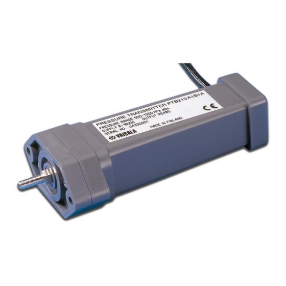
Chapter 2 – Product overview Figure 1 PTB210 with standard accessories PTB210 uses the Vaisala BAROCAP sensor, a silicon capacitive absolute pressure sensor developed by Vaisala for barometric pressure applications. The Vaisala BAROCAP sensor provides excellent hysteresis and repeatability characteristics and outstanding temperature and long-term stability. -
Page 10: Safety
Only licensed experts may install electrical components. They must adhere to local and state legislation and regulations. 2.3 Trademarks Vaisalaâ and BAROCAPâ are registered trademarks of Vaisala Oyj. Windowsâ is either a registered trademark or trademark of Microsoft Corporation in the United States and other countries. -
Page 11: Installation
Chapter 3 – Installation 3. Installation 3.1 Mounting PTB210 Due to the compact design of PTB210, you only need to mount the instrument and connect the wires. Choose one of the following 3 mounting options. • Remove the pressure fitting and place the barometer on a desired structure. Attach it with slot-headed screws the O-ring sealing the attachment (A). -
Page 12: Static Pressure Head
PTB210 has IP65 housing. You can mount it outdoors without any additional protection. Make sure that rainwater cannot block the open pressure fitting. Vaisala recommends connecting a piece of a tube with inner diameter of 4 mm or more to the fitting. -
Page 13: Connections
Chapter 3 – Installation 3.2 Connections There are 3 different serial output interfaces available for PTB210 digital barometers: • RS-232C • RS-485/232C • RS-232C/TTL The connections depend on the output protocol in use. Vaisala recommends isolating the free wire ends. -
Page 14: Table 2 Ptb210 Wiring With Rs-232C
PTB210 Series User Guide M210669EN-E Table 2 PTB210 wiring with RS-232C Wire color Signal Grey Green Blue Ground Pink Supply voltage (5 ... 28 V DC) Brown Not connected White Not connected Yellow Power down mode (TTL level: 0 V = off, 5 V = on) Table 3 PTB210 wiring with RS-485/RS-232C interface... - Page 15 Chapter 3 – Installation The 2 output protocols cannot be used simultaneously. Connect either RX/TX or RXD/TXD wires. More information ‣ .RON/ .ROFF setting RS-485 terminating resistor on/off (page 18)
-
Page 16: Operation
PTB210 Series User Guide M210669EN-E 4. Operation PTB210 can be operated through a serial line by using suitable terminal software like Windows® Hyper Terminal. The commands are described in the following pages. The format of the commands is .ZZZ.xxx Defines an event... -
Page 17: Setting Serial Communication Parameters
Chapter 4 – Operation 4.1.2 Setting serial communication parameters The following parameter combinations are available for PTB210. The factory setting for the parameters is E71. .E71 .O71 .N81 The command sets the serial communication parameters of either a single barometer or all the barometers. -
Page 18: Mpm Measurements Per Minute
PTB210 Series User Guide M210669EN-E xxxx Higher pressure limit 4.1.5 .MPM measurements per minute .MPM.xxx Number of measurements per minute (6 ... 4200) The command sets the number of measurements performed in one minute. As default, the MPM is 60. 60 min... -
Page 19: Bp Continuous Output
Chapter 4 – Operation 4.2.2 .BP continuous output The command outputs the multi-point corrected pressure reading continuously. The output interval depends on the measurement rate and the averaging. To stop the output, press ENTER. .P<cr> (command invisible) 997.99 998.01 998.01 998.02 <cr>... -
Page 20: Reset Reset Instrument
PTB210 Series User Guide M210669EN-E 1017.61 The command adds the unit to the output. The standard output field is for 6 characters. The first character is always a space. 1017.61 hPa 4.2.5 .RESET reset instrument .RESET The command resets the barometer and activates the setting changes. -
Page 21: Self-Testing
Chapter 4 – Operation In case several barometers are connected to same line, set on only the resistor of the last one. The others must be off. This prevents formation of excessive load on the line. The maximum amount of barometers on same line is 32. At the end of the serial bus there must be PTB210, a dynamic line adapter, or a line master. - Page 22 PTB210 Series User Guide M210669EN-E .?<cr> (command not visible) PTB210 Ver 1.0 CAL DATE :1999-06-10 ID CODE :10 SERIAL NUMBER :T00100004 MULTIPOINTCORR:ON MEAS PER MINUTE: 60 AVERAGING : 0 PRESSURE UNIT : hPa Pressure Min...Max: 500 1100 (50 1100 for model 50…1100)
-
Page 23: Calibration And Adjustment
• For the Class A barometers, use standards with uncertainty of 70 ppm (2 standard deviation value), or better. • For the Class B barometers, Vaisala recommends electronic working standards with uncertainty of 150 ppm. Calibration does not include any adjustments. - Page 24 PTB210 Series User Guide M210669EN-E The Wizard software uses the RS-232 or RS-485 interface. If you use the TTL level, disconnect the RXD/TXD wires and connect the RX/TX wires. See Table 2 (page 12). 1. Go to http://www.vaisala.com/PTB210Wizard/. PTB210_calibration_wizard.zip downloads.
- Page 25 Chapter 5 – Calibration and adjustment 6. Type the reference pressure values and the corresponding corrections. Calculate the corrections according to the following equation. You can also change the settings on the left. corr = P reference measured The values are in hPa. The reference value is as whole number and the correction with 2 decimals.
- Page 26 PTB210 Series User Guide M210669EN-E 8. When prompted for a password, select OK. By default, there is no password. You can protect the new corrections with a password. To enter a password, select the Change. 9. Type a new password and type it again when prompted.
-
Page 27: Technical Data
Chapter 6 – Technical Data 6. Technical Data 6.1 PTB210 specifications Table 5 PTB210 measurement performance Property Description/Value Pressure range Serial output 500 … 1100 hPa 50 … 1100 hPa Analog output 500 … 1100 hPa 600 … 1060 hPa 800 … 1060 hPa 900 …... -
Page 28: Table 6 Ptb210 Operating Environment
PTB210 Series User Guide M210669EN-E Property Description/Value ± 0.15 hPa Calibration uncertainty ± 0.30 hPa Accuracy at +20 °C (+68 °F) ± 0.50 hPa Temperature dependency ± 0.60 hPa Total accuracy -40 … +60 °C (-40 … +140 °F) Long-term stability ±... -
Page 29: Table 8 Ptb210 Mechanical Specifications
Chapter 6 – Technical Data Property Description/Value Resolution 0.01 hPa (1 measurement/s) 0.03 hPa (10 measurements/s) Current consumption, normal mode < 15 mA (factory setting) Current consumption, shutdown mode 0.2 mA Analog output Outputs 0 … 5 V DC, 0 … 2.5 V DC (order specified) Shutdown ON/OFF... -
Page 30: Figure 4 Ptb210 Dimensions
PTB210 Series User Guide M210669EN-E Table 9 PTB210 compliance Property Description/Value Directives EMC Directive (2014/30/EU) RoHS Directive (2011/65/EU) EMC compatibility EN / IEC 61326-1, Electrical equipment for measurement, control and laboratory use - EMC requirement; Basic environment CISPR 32 / EN 55032, Class B... -
Page 31: Appendix A: Fcc Part 15 Compliance Statement
Appendix A – FCC Part 15 compliance statement Appendix A. FCC Part 15 compliance statement This equipment has been tested and found to comply with the limits for a Class B digital device, pursuant to Part 15 of the FCC rules. These limits are designed to provide reasonable protection against harmful interference in a residential installation. -
Page 33: Warranty
Please see the applicable supply contract or Conditions of Sale for details of the warranty for each product. Technical support Contact Vaisala technical support at helpdesk@vaisala.com. Provide at least the following supporting information as applicable: • Product name, model, and serial number •... - Page 36 www. v aisala.com...
Need help?
Do you have a question about the PTB210 Series and is the answer not in the manual?
Questions and answers