Table of Contents
Advertisement
Quick Links
Advertisement
Table of Contents

Related Manuals for Vaisala AWS310


Summary of Contents for Vaisala AWS310
- Page 1 M211948EN-B Installation Manual Vaisala Automatic Weather Station AWS310...
- Page 2 This product contains software developed sold or disclosed to a third party without by Vaisala or third parties. Use of the prior written permission of the copyright software is governed by license terms and holder. Translated manuals and translated...
-
Page 3: Table Of Contents
Table of Contents Table of Contents About This Document..................9 Version Information....................9 Related Manuals..................... 9 Documentation Conventions................10 Trademarks......................11 Product Overview....................13 Vaisala Automatic Weather Station AWS310............ 13 2.1.1 AWS310 Observations................... 14 2.1.2 Standard Installation..................15 2.1.3 Delivery and Maintenance................16 Product Nomenclature..................16 Safety........................ - Page 4 AWS310 Installation Manual M211948EN-B Sensor Installation.....................47 Overview of Sensor Installation................. 47 Installing WMT700....................47 7.2.1 Placing WMT700...................48 7.2.2 Unpacking and Handling WMT700............49 7.2.3 Connecting WMT700 Cable................ 50 7.2.4 Mounting WMT700 on Vertical Pole Mast..........53 7.2.5 Mounting WMT700 on Sensor Support Arm or Cross Arm Using WMT70FIX..................
- Page 5 Table of Contents 10. Enclosure Installation..................139 10.1 Overview of Enclosure Installation..............139 10.2 Installing BOX652....................140 10.3 Installing BOX652 on Pole Mast............... 142 10.4 Installing BOX652 with Mounting Frame on Wall or Back Panel....154 10.5 Installing BOX652 without Mounting Frame on Wall or Back Panel....162 10.6 Finalizing BOX652 Installation.................
- Page 6 QML Data Logger Connector Block..............199 AWS310 Block Diagram (Serial Wiring)............202 AWS310 Block Diagram (Ethernet Wiring)............203 TERMBOX Wiring Diagrams................204 AWS310 Wiring Diagrams for Serial Wiring..........204 A.5.1 Wiring Diagram for Power Connections (Serial Wiring)....... 205 A.5.2 Wiring Diagram for RS‑232, RS‑485, SDI‑12 Connections (Serial Wiring)....................
- Page 7 Mounting WMT700 on Side of Mast............54 Figure 15 Mounting WMT700 on Top of Mast.............54 Figure 16 WMT700 North Arrow..................59 Figure 17 Vaisala Serial Wind Transmitter WAC155............ 61 Figure 18 Contents of Shipping Container..............67 Figure 19 Installing with Protective Packaging............68 Figure 20 WXT530 (WXT536) Pole Mast Installation Accessories......70...
- Page 8 Installing Radiation Shield on BOX652 Installed on Wall.....166 Figure 57 TERMBOX Installed in Pole Mast..............168 Figure 58 TERMBOX Grounding..................170 Figure 59 AWS310 Main Components Inside BOX652..........175 Figure 60 AWS310 Layout Example, Bottom View...........180 Figure 61 Rubber Flange AWSENCLFLANGE1............180 Figure 62 Leading Cables to Enclosure (Rubber Flange)........
- Page 9 List of Tables List of Tables Table 1 Document Versions....................9 Table 2 AWS310 Manuals....................9 Table 3 Related Manuals..................... 9 Table 4 System Components....................16 Table 5 Sensors........................17 Table 6 Recommended Tilt Angle for Solar Panel........... 136 Table 7 QML Data Logger LED Blinking Sequences..........
- Page 10 AWS310 Installation Manual M211948EN-B...
-
Page 11: About This Document
1.2 Related Manuals The manuals listed in the following tables are provided on a USB stick delivered with the station. Printed versions of the AWS310 manuals can be ordered separately. Documentation by third-party instrument manufacturers is provided as is. Table 2 AWS310 Manuals... -
Page 12: Documentation Conventions
M210293EN Vaisala Anemometer WAA151 User's Guide M210294EN Vaisala Wind Vane WAV151 User's Guide M210822EN Vaisala Serial Wind Transmitter WAC155 User's Guide M211840EN Vaisala Weather Transmitter WXT530 Series User Guide â Humidity and Temperature Probe HMP155 User's Guide M210912EN Vaisala HUMICAP â... -
Page 13: Trademarks
Indicates that you need to take some notes during the task. 1.4 Trademarks Vaisala â , BAROCAP â , HUMICAP â , RAINCAP â , and WINDCAP â are registered trademarks of Vaisala Oyj. HydroMet ™ is a trademark of Vaisala Oyj. - Page 14 AWS310 Installation Manual M211948EN-B...
-
Page 15: Product Overview
• GOES data message When AWS310 is used as an observation station in the Vaisala Observation Network Manager NM10 system, the data collected from AWS310 can be accessed in NM10 with a browser-based interface. NM10 enables centralized remote monitoring and control of observation stations, and provides a wide range of options for storing, exporting and visualizing data. -
Page 16: Aws310 Observations
AWS310 Installation Manual M211948EN-B 2.1.1 AWS310 Observations Figure 1 Sensors Supported by AWS310 Depending on the installed sensors, AWS310 can measure the following weather parameters: • Air temperature and humidity • Barometric pressure • Cloud height • Precipitation accumulation and intensity • Present weather and visibility •... -
Page 17: Standard Installation
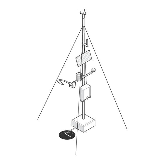
• Wind gust 2.1.2 Standard Installation In standard AWS310 installations, many sensors and solar panels are installed on a mast and connected to the central enclosure which houses the QML data logger, electronics components, and batteries. A wall mount set for the AWS310 enclosure is also available. -
Page 18: Delivery And Maintenance
M211948EN-B 2.1.3 Delivery and Maintenance AWS310 requires only a minimal amount of regular maintenance and can be trusted to perform effectively in all weather conditions and climates. The modular design of the weather station allows easy integration of additional sensors even after initial installation and permits quick replacement of individual components, reducing downtime and overall operating cost. -
Page 19: Table 5 Sensors
Vaisala Tiltable Pole Mast DKE110W Vaisala Composite Pole Mast, white or red/orange and white DKE110AV DKP060SUP1 Vaisala sensor support arm for 60‑mm (2.36‑in) masts, half-length or full-length DKP060SUP2 DKP12SUP1 Vaisala sensor support arm for 100‑mm (3.94‑in) masts, half-length or full-length DKP12SUP2 Table 5 Sensors... -
Page 20: Safety
M211948EN-B Item Common/Full Name PWD22 Vaisala Present Weather Detector QMR102 Vaisala Precipitation Sensor RG13(H) Vaisala Rain Gauge (with heating) OTT Precipitation Gauge OTT Pluvio CL31 Vaisala Ceilometer SR50A Campbell Scientific Ultrasonic Water and Snow Level Sensor PAA-36 X W Keller Water Level and Temperature Transmitter... - Page 21 Chapter 2 – Product Overview WARNING! Do not service the system alone. Do not reach into parts and assemblies that are AC (mains) powered and live except in the presence of someone who can provide first aid. WARNING! Do not perform installation or maintenance procedures when there is a risk of thunderstorm or lightning activity in the area.
- Page 22 WARNING! Failure to comply with these precautions or with specific warnings elsewhere in these instructions violates safety standards of design, manufacture, and intended use of the product. Vaisala assumes no liability for the customer's failure to comply with these requirements.
-
Page 23: Esd Protection
Chapter 2 – Product Overview WARNING! If the equipment is used in a manner not specified by Vaisala, the protection provided by the equipment may be impaired. CAUTION! Do not damage or change the wiring. Incorrect wiring can cause damage and prevent or limit operation. - Page 24 AWS310 Installation Manual M211948EN-B...
-
Page 25: Installation Preparation
4. Install the AWS Client to a laptop and collect all required information needed to configure the system. For more information, see Vaisala Automatic Weather Station AWS310 Configuration and Maintenance Manual. 5. Collect all tools required for the mechanical installation. -
Page 26: Placing Antennas
AWS310 Installation Manual M211948EN-B To protect the humidity and air temperature sensor from direct sunlight, always use a radiation shield. In general, there must be at least 150 m (492 ft) of open area to all directions from the mast. - Page 27 Chapter 3 – Installation Preparation • Heat sources • Swamps • High vegetation • Places that may hold water after rain To ensure correct measurements, align wind sensors or the weather transmitter as instructed. The wind direction can refer either to true North, which uses the earth's geographic meridians, or to the magnetic North, which is read with a magnetic compass.
-
Page 28: Planning Layout
AWS310 Installation Manual M211948EN-B 3.3.3.2 Placing Subsurface Sensors For the soil temperature sensor, the measurement site must be 1 m (10.76 sq ft) and typical of the surface of interest. The ground surface must be level with respect to the immediate (10 m / 32 ft 10 in radius) area. -
Page 29: Preparing Site
Chapter 3 – Installation Preparation The following figure shows the layout that the default installation kit supports. If your site layout requires different placements, prepare for them when ordering your equipment by, for example, planning for different cable lengths. For more information about available options for each sensor, see the relevant sensor documentation. -
Page 30: Laying Foundations
For detailed instructions on how to lay concrete foundations for the mast, ceilometer, and precipitation gauge, see the following documents: • Vaisala Composite Pole Mast DKE110W and DKE110AV User Guide • Vaisala Short Pole Mast DKP202, DKP203, DKP204, and DKP204W-CAMPOLE User Guide • Vaisala Tiltable Pole Mast DKP206 and DKP210 User Guide •... -
Page 31: Figure 4 Drw231218 Foundation Round Rg13(H)
Chapter 3 – Installation Preparation Figure 4 DRW231218 Foundation Round RG13(H) Foundation accessories Surface level Reinforcement bar Conduit... -
Page 32: Figure 5 Drw231219 Foundation Square Rg13(H)
AWS310 Installation Manual M211948EN-B Figure 5 DRW231219 Foundation Square RG13(H) Foundation accessories Surface level Wedge bolt More Information ‣ Installing QMR102 (page 110) ‣ Installing RG13(H) (page 111) 3.5.2.1 Concrete Reinforcing • Concrete quality must be better than K30. If the foundation is prefabricated, the... - Page 33 Chapter 3 – Installation Preparation • Preferable conduit type: • Material: PVC • Minimum diameter: 50 mm (1.97 in) • All conduits sealed with plugs to prevent water entry • Pullstrings placed in all conduits Center the reinforcement in the concrete foundation.
-
Page 34: Figure 6 Drw231233 Round Concrete Reinforcing Fs11, Fd12, Cl31
AWS310 Installation Manual M211948EN-B Figure 6 DRW231233 Round Concrete Reinforcing FS11, FD12, CL31, and RG13 All bars are joined with steel thread, Ø 1.5 mm (0.16 in) (see detail A) or welded (see detail B) Item 1: length 400 mm (15.75 in) (20 pcs) Item 2: length 520 mm (20.47 in) (20 pcs) -
Page 35: Power Supply And Communication Lines
Check the contents against the packing list provided in a plastic folder or inside the shipping box. For customized systems, check the packing list and system documentation. More Information ‣ Preparing for Installation (page 23) 3.7 Necessary Tools and Equipment The following tools are required for the installation (not supplied by Vaisala):... - Page 36 • Cable cutters • Crowbar • Hammer The following equipment is required for the installation (not supplied by Vaisala): • Safety helmet, safety boots, safety glasses, gloves, high visibility clothing, and other appropriate safety equipment • Dozens of cable ties in different sizes •...
-
Page 37: Overview Of Installation
14.1 Finalizing and Checking Installation (page 197) To configure the weather station after the mechanical installation, use a laptop with the AWS Client installed. For more information, see Vaisala Automatic Weather Station AWS310 System Description or Vaisala Automatic Weather Station AWS310 Configuration and Maintenance Manual. WARNING! Do not perform installation or maintenance procedures when there is a risk of thunderstorm or lightning activity in the area. - Page 38 AWS310 Installation Manual M211948EN-B...
-
Page 39: Mast Installation
(2.36 in), 75 mm (2.95 in), 100 mm (3.94 in), or 106 mm (4.17 in) • Wall mounting kit For detailed instructions on how to install a Vaisala mast, see the appropriate mast manual: • Vaisala Composite Pole Mast DKE110W and DKE110AV User Guide •... -
Page 40: Component Placement On Pole Mast
5.2 Component Placement on Pole Mast The following figure gives guidelines for placing the sensor support arm, BOX652 enclosure, and TERMBOX on Vaisala Tiltable Pole Mast DKP210. You can use the figure as a guideline also for other types of masts. -
Page 41: Grounding And Lightning Protection
Vaisala recommends an air terminal for all mast structures that reach 10 m (32 ft 10 in). For mast structures that reach 6 m (19 ft 8 in) or lower, an air terminal is recommended in regions with high lightning density. - Page 42 For instructions and guidance on how to set up grounding and lightning protection for the station, see Grounding and Lightning Protection in Vaisala Outdoor Installations Technical Reference and Lightning Protection Kits DKL201, DKL202, and DKL203 Technical Reference.
-
Page 43: Sensor Support Arm Installation
Chapter 6 – Sensor Support Arm Installation 6. Sensor Support Arm Installation 6.1 Overview of Sensor Support Arm Installation Before starting the installation, plan carefully how many sensor support arms you need and where to install them. The number and positioning of sensor support arms depends on the sensors that you are going to install. -
Page 44: Figure 8 Mounting Sensor Support Arm Assembly Dkp12Sup
AWS310 Installation Manual M211948EN-B Figure 8 Mounting Sensor Support Arm Assembly DKP12SUP Sensor support arm Mounting flat U-bolt M8 Mounting plate Flat washer A6.4 DIN125 A4 (10 pcs) Spring lock washer B6 DIN127 A4 (10 pcs) Hex screw M6×16 DIN912 A4 (10 pcs) -
Page 45: Figure 9 Mounting Sensor Support Arm Assembly Dkp060Sup
Chapter 6 – Sensor Support Arm Installation Figure 9 Mounting Sensor Support Arm Assembly DKP060SUP Mounting flat Sensor support arm APPK-SET Hex screw M6×16 DIN912 A4 (14 pcs) Spring lock washer B6 DIN127 A4 (14 pcs) Flat washer A6.4 DIN125 A4 (14 pcs) Mounting plate 1. -
Page 46: Mounting Half-Length Sensor Support Arm
AWS310 Installation Manual M211948EN-B 6.3 Mounting Half-length Sensor Support • 5‑mm Allen key • 13‑mm wrench... -
Page 47: Figure 10 Mounting Half Sensor Support Arm Dkp12Sup
Chapter 6 – Sensor Support Arm Installation Figure 10 Mounting Half Sensor Support Arm DKP12SUP Sensor support arm DKP12SUP U-bolt M8 Mounting plate Flat washer A6.4 DIN125 A4 (4 pcs) Spring lock washer B6 DIN127 A4 (4 pcs) Hex screw M6×16 DIN912 A4 (4 pcs) Spring lock washer B8 DIN127 A4 (4 pcs) Hex nut M8 DIN934 A4 (4 pcs) -
Page 48: Figure 11 Mounting Half Sensor Support Arm Dkp060Sup
AWS310 Installation Manual M211948EN-B Figure 11 Mounting Half Sensor Support Arm DKP060SUP Hex screw M6×30 DIN912 A4 (4 pcs) Spring lock washer A6 DIN127 A4 (4 pcs) Flat washer A6 DIN125 A4 (4 pcs) Sensor support arm DKP060SUP Mounting plate APPK-SET 1. -
Page 49: Sensor Installation
Chapter 7 – Sensor Installation 7. Sensor Installation 7.1 Overview of Sensor Installation Follow the instructions relevant to the sensors in your installation: • Sensors installed on the mast or on sensor support arm: • 7.2 Installing WMT700 (page 47) • 7.3 Installing WA15 (page 60) •... -
Page 50: Placing Wmt700
AWS310 Installation Manual M211948EN-B 7.2.1 Placing WMT700 Install WMT700 on one of the following: • Side of the mast • Top of the mast • Sensor support arm or cross arm If you have 2 WMT700 sensors, install both on a sensor support arm. -
Page 51: Unpacking And Handling Wmt700
Chapter 7 – Sensor Installation 7.2.2 Unpacking and Handling WMT700 WMT700 is shipped in a custom cardboard container with two plastic transportation dampers. When unpacking WMT700, remove only the bottom damper that protects the sensor body. CAUTION! Never transport WMT700 without the custom shipping container. Otherwise, the warranty becomes void. -
Page 52: Connecting Wmt700 Cable
AWS310 Installation Manual M211948EN-B Figure 13 Handling WMT700 7.2.3 Connecting WMT700 Cable When mounting to a mast, you can the route cable either outside or inside the mast. Cable routing depends on the mast type and other equipment, such as air terminals, installed on the mast. - Page 53 1. If you are using the cable tightening tool, insert the cable in the tool. Vaisala recommends that you use the cable tightening tool. The ribbed part of the tool offers a better grip of the cable when tightening the connector. You do not need to remove the tool when the connector is tightened.
- Page 54 AWS310 Installation Manual M211948EN-B 3. Connect the cable to WMT700. Tighten the cable by rotating the tightening tool or the ribbed part of the connector clockwise by hand. Make sure that the connector is properly tightened before proceeding to the next step.
-
Page 55: Mounting Wmt700 On Vertical Pole Mast
Chapter 7 – Sensor Installation 7.2.4 Mounting WMT700 on Vertical Pole Mast • 5-mm Allen key • Adjustable wrench You can mount WMT700 on a 30‑mm (1.18‑in) or a 60‑mm (2.36‑in) pole mast. The WMT70FIX mounting kit contains U bolts for both kinds of pole masts (2 pcs each). You can place WMT700 either on the side or on top of the mast. -
Page 56: Figure 14 Mounting Wmt700 On Side Of Mast
AWS310 Installation Manual M211948EN-B 2. Assemble the WMT70FIX mounting kit, and attach it to the mast with the U bolts. Figure 14 Mounting WMT700 on Side of Mast When mounting the sensor on the side of the mast, make sure that the mounting kit is positioned at the top level of the mast. - Page 57 Chapter 7 – Sensor Installation 5. Holding the sensor from its body, run the cable through the WMT70FIX mounting kit, and slide the sensor into the mounting kit.
-
Page 58: Mounting Wmt700 On Sensor Support Arm Or Cross Arm Using Wmt70Fix
AWS310 Installation Manual M211948EN-B 6. To avoid misalignment, turn the sensor until the mounting screw reaches the far end of the slot, and tighten the screw. Tightening torque 5 Nm. WMT700 mounting screw U-bolt and nut (M8 DIN934 A4) in horizontal slot 7. - Page 59 Chapter 7 – Sensor Installation 2. Attach the WMT70FIX mounting kit to the sensor support arm or cross arm with the U bolts and insert the U bolts in the slots of the mounting kit. 3. Check that the mounting kit is not tilted to either side and tighten the U bolts firmly. 4.
-
Page 60: Aligning Wmt700
AWS310 Installation Manual M211948EN-B 6. To avoid misalignment, turn the sensor until the screw reaches the far end of the slot, and tighten the screw. WMT700 mounting screw. Tightening torque 5 Nm. U-bolt and nut (M8 DIN934 A4) in horizontal slot 7. -
Page 61: Figure 16 Wmt700 North Arrow
Chapter 7 – Sensor Installation Figure 16 WMT700 North Arrow Do not remove the instrument or sensor from the mounting kit during alignment. 1. Remove the transportation damper that protects the array and store it for future use. 2. To align the sensor, use a compass or other similar method to rotate the sensor so that the North arrow points North. -
Page 62: Installing Wa15
3. In AWS Client, set the deviation angle for the wind sensor with the wdoffset_1 (first wind sensor) or wdoffset_2 (second wind sensor) parameter. For more information, see Vaisala Automatic Weather Station AWS310 Configuration and Maintenance Manual. The sensor transmits the wind direction data by using the changed zero alignment. -
Page 63: Figure 17 Vaisala Serial Wind Transmitter Wac155
Chapter 7 – Sensor Installation Figure 17 Vaisala Serial Wind Transmitter WAC155 Flange for mounting Vaisala anemometer Flange for mounting Vaisala wind vane Transmitter, contains the component board Sensor cable gland Cross arm CAUTION! To prevent equipment damage, install an air terminal so that the tip is as high above the instruments and sensors as possible. -
Page 64: Mounting Wind Sensors On Cross Arm
AWS310 Installation Manual M211948EN-B 7.3.1 Mounting Wind Sensors on Cross Arm • 2-mm Allen key • Compass 1. Fit the cable plug through the mounting flange at the end of the cross arm, and connect the cable to the sensor. Plastic washer Hex screw 2. -
Page 65: Mounting Wind Set On Mast
Chapter 7 – Sensor Installation 7.3.2 Mounting Wind Set on Mast 6‑mm Allen key You can install the wind set on top of a 60‑mm (2.36‑in) mast. 1. Place the cross arm on the mast. 2. Tighten the bolts. Tightening torque 5 Nm. 3. -
Page 66: Connecting Wind Transmitter Cable
AWS310 Installation Manual M211948EN-B 7.3.3 Connecting Wind Transmitter Cable • Cable cutters • Cable stripper • Slothead screwdriver 1. Remove the four screws holding the cover of the junction box. Remove the cover. 2. Lead the sensor cable through the cable gland. -
Page 67: Aligning Wind Set
Chapter 7 – Sensor Installation 6. Tighten the output cable glands properly. When installing the equipment for example in tropical, marine, or cold temperature environments, keep the equipment within its specific operating conditions. To avoid dust, dirt, or water to enter the equipment, tighten the cable glands properly. 7. -
Page 68: Installing Wxt530
AWS310 Installation Manual M211948EN-B 7.4 Installing WXT530 These instructions are valid for WXT530 series weather transmitters. You can install the instrument on top of a pole mast or on a sensor support arm. For the most reliable measurements: • Avoid trees or other objects nearby which could disturb wind flow. -
Page 69: Unpacking Wxt530
Chapter 7 – Sensor Installation 7.4.1 Unpacking WXT530 The transmitter comes in a custom shipping container. The following figure shows the contents of the carton. Figure 18 Contents of Shipping Container Protective packaging top Shipping carton Inner box Manual, cables, mounting kit (optional) Installation note Protective packaging bottom Transmitter... -
Page 70: Figure 19 Installing With Protective Packaging
AWS310 Installation Manual M211948EN-B CAUTION! Be careful not to damage the wind transducers located at the top of the three antennas. Dropping the device can break or damage the transducers. If the antenna bends or twists, re-aligning can be difficult or impossible. -
Page 71: Mounting Wxt530
Chapter 7 – Sensor Installation 7.4.2 Mounting WXT530 The transmitter is easy to install as it does not have any moving parts. The transmitter can be mounted on: • Vertical pole mast • Sensor support arm Install the transmitter upright. The transmitter radiation shield reflects light. If you install the transmitter next to a pyranometer or a temperature and humidity sensor, the pyranometer or temperature and humidity sensor can give incorrect measurements. -
Page 72: Figure 20 Wxt530 (Wxt536) Pole Mast Installation Accessories
AWS310 Installation Manual M211948EN-B Figure 20 WXT530 (WXT536) Pole Mast Installation Accessories Mounting kit (212792) Mounting adapter (WMSFIX60) CAUTION! Handle with care. Any impact on the instrument or sensor array may cause damage and lead to incorrect measurements. 1. Remove the adapter sleeve from the mounting kit. - Page 73 Chapter 7 – Sensor Installation 3. Insert the mounting kit adapter to the transmitter bottom. Protective cushion Transmitter Mounting kit Pole 4. Turn the kit firmly until you feel the adapter snap into the locked position.
- Page 74 AWS310 Installation Manual M211948EN-B 5. Holding the sensor from its body, run the sensor cable through the mounting adapter, and slide the sensor onto the adapter. Do not tighten the fixing screw yet. Fixing screw. Tightening torque 1.5 Nm. Mounting accessory between...
- Page 75 Chapter 7 – Sensor Installation 8. Remove the protective cushion. When removing a transmitter from the pole, turn the transmitter so that it snaps out from the mounting kit. Realignment is not needed when replacing the device. More Information ‣ Aligning WXT530 (page 75) 7.4.2.2 Mounting WXT530 on Sensor Support Arm 10‑mm wrench If you use the optional mounting kit, you only need to align the sensor when mounting it for...
- Page 76 AWS310 Installation Manual M211948EN-B 2. Align the sensor support arm in South–North direction. If you cannot align the sensor support arm, adjust the wind direction offset. 3. Mount the transmitter on the sensor support arm. Nut M6 DIN 934 Mounting bolt M6 DIN 933...
-
Page 77: Aligning Wxt530
Chapter 7 – Sensor Installation More Information ‣ Aligning WXT530 (page 75) 7.4.3 Aligning WXT530 To help the alignment, there is an arrow and the text North on the bottom of the transmitter. Align the transmitter so that the arrow points North. Figure 21 WXT530 North Arrow Wind direction can be referred either to true North, which uses the Earth’s geographic meridians, or to the magnetic North, which is read with a magnetic compass. -
Page 78: Installing Hmp155
AWS310 Installation Manual M211948EN-B Do not remove the instrument or sensor from the mounting kit during alignment. 1. If the transmitter is mounted, loosen the fixing screw on the bottom of the transmitter so that you can rotate it. 2. Use a compass to determine that the transducer heads of the transmitter are exactly in line with the compass and that the arrow on the bottom of the transmitter points North. - Page 79 Chapter 7 – Sensor Installation Mount the humidity and temperature probe at the opposite end of the sensor support from the solar radiation sensor.
-
Page 80: Figure 22 Hmp155 And Dtr503A Installation Accessories
AWS310 Installation Manual M211948EN-B Figure 22 HMP155 and DTR503A Installation Accessories Radiation shield (DTR503A) Sensor support arm (212564) Flat washer A6.4 DIN125 A4 (2 pcs) Spring lock washer B6 DIN127 A4 (2 pcs) Hex screw M6×16 DIN912 A4 (2 pcs) HMP155 The package also contains a pole mounting kit. - Page 81 Chapter 7 – Sensor Installation 1. Install the radiation shield on the sensor support arm. Radiation shield Sensor support arm Flat washer A6.4 DIN125 A4 (2 pcs) Spring lock washer B6 DIN127 A4 (2 pcs) Hex screw M6×16 DIN912 A4 (2 pcs). Tightening torque 5 Nm. 2.
- Page 82 AWS310 Installation Manual M211948EN-B 3. Lead the sensor cable through the connector cover, and attach the cable to the probe. 4. Loosen the compression fitting with your fingers and insert the probe inside the ring. Pay attention to the rubber insert.
-
Page 83: Mounting Hmp155 Inside Radiation Shield Dtr13
Chapter 7 – Sensor Installation 5. Tighten the compression fitting until it locks in place. CAUTION! Avoid using excessive force. 6. Push the connector cover over the sensor connector. 7. Lead the sensor cable along the sensor support arm and attach it with cable ties. 8. -
Page 84: Figure 23 Hmp155 And Dtr13 Installation Accessories
AWS310 Installation Manual M211948EN-B Figure 23 HMP155 and DTR13 Installation Accessories Radiation shield (DTR13) Sensor support arm (212564) Flat washer A6.4 DIN125 A4 (2 pcs) Spring lock washer B6 DIN127 A4 (2 pcs) Hex screw M6×16 DIN912 A4 (2 pcs) HMP155... - Page 85 Chapter 7 – Sensor Installation 1. Install the radiation shield on the sensor support arm. Radiation shield Sensor support arm Flat washer A6.4 DIN125 A4 (2 pcs) Spring lock washer B6 DIN127 A4 (2 pcs) Hex screw M6×16 DIN912 A4 (2 pcs). Tightening torque 5 Nm. 2.
- Page 86 AWS310 Installation Manual M211948EN-B 3. Lead the sensor cable through the connector cover, and attach the cable to the probe.
- Page 87 Chapter 7 – Sensor Installation 4. Insert the HMP155 probe in the larger outer hole at the bottom of the radiation shield. If you are installing the additional T-probe, insert it to the smaller outer hole. Hole for additional T-probe Hole for HMP155 probe 5.
-
Page 88: Installing Hmp110
AWS310 Installation Manual M211948EN-B 7.6 Installing HMP110 Adjustable wrench Mount the humidity and temperature probe at the opposite end of the sensor support from the solar radiation sensor. DTR504 with probe installation kit includes a rain/solar radiation shield DTR504 and a plastic installation support for HMP110. -
Page 89: Installing Qmn101
Chapter 7 – Sensor Installation More Information ‣ Connecting Sensor and Device Cables (page 178) 7.7 Installing QMN101 • 5‑mm Allen key • Compass Install QMN101 1.5 … 3 m (4 ft 11 in … 9 ft 10 in) above the ground surface at the end of the sensor support arm. -
Page 90: Installing Smp Series And Suv5 Sensors
AWS310 Installation Manual M211948EN-B 2. Attach the sensor to the fixing plate. You can align the sensor to the sensor support arm or at 60° at either direction. 3. Guide the cable through the sensor support arm and through the opening in the sensor support arm. - Page 91 Chapter 7 – Sensor Installation • Install the pyranometer on a mounting plate. Temperature fluctuations of the pyranometer body can produce offset signals. The non-conducting materials of the mounting plate thermally isolate the sensor from its fixtures. • Make sure that the sensor is level. WARNING! Do not perform installation or maintenance procedures when there is a risk of thunderstorm or lightning activity in the area.
-
Page 92: Figure 26 Installing Smp Series Pyranometer (Radiation Shield Removed)
AWS310 Installation Manual M211948EN-B Figure 26 Installing SMP Series Pyranometer (Radiation Shield Removed) Sensor support arm Mounting plate KZFIXPLATE SMP series pyranometer Spring lock washer B6 DIN127 A4 (2 pcs) Hex screw M6×16 DIN912 A4 (2pcs) Screw M5 (2 pcs), included in the pyranometer package... -
Page 93: Installing Sp Lite2
Chapter 7 – Sensor Installation 6. To level the sensor, turn the leveling screws. Use the screw nearest to the spirit level first. When the sensor is straight according to the spirit level, the thermopile is horizontal within 0.05 °. This causes a maximum azimuthal variation of ±0.5 % at a solar elevation of 10 °. -
Page 94: Figure 27 Sp Lite2 Installation Accessories
AWS310 Installation Manual M211948EN-B Figure 27 SP Lite2 Installation Accessories Leveling screw (3 pcs), included in the pyranometer package Hex screw (2 pcs), included in the pyranometer package Washer (4 pcs), included in the pyranometer package Hex nut (2 pcs), included in the pyranometer package... - Page 95 Chapter 7 – Sensor Installation To prevent corrosion and oxidation, use copper paste or equivalent on screws and connector threads. 1. Attach the leveling screws into the holes on the sensor.
- Page 96 AWS310 Installation Manual M211948EN-B 2. Place the sensor on the mounting plate and attach it with the hex screws. Tighten the screws so that the leveling screws lightly touch the mounting plate. Hex screw (2 pcs) Washer (4 pcs) Mounting plate...
- Page 97 Chapter 7 – Sensor Installation 3. Attach the mounting plate to the sensor support arm. Spring lock washer B6 DIN127 A4 (2 pcs) Hex screw M6×16 DIN912 A4 (2 pcs) 4. To level the sensor, use the spirit level on the sensor. Turn the leveling screws accordingly, starting from the one nearest to the spirit level.
-
Page 98: Installing Csd3
AWS310 Installation Manual M211948EN-B More Information ‣ Connecting Sensor and Device Cables (page 178) 7.10 Installing CSD3 • 7‑mm wrench • 5 mm and 6 mm Allen keys Install CSD3 in the middle or at the end of a sensor support arm. -
Page 99: Figure 29 Csd3 Installation Accessories For End Of Sensor Support Arm
Chapter 7 – Sensor Installation Figure 29 CSD3 Installation Accessories for End of Sensor Support Arm Spring lock washer A6 DIN125 (2 pcs) Spring lock washer A6 DIN127 (2 pcs) Hex screw M6×25 ISO7380 (2 pcs) Sensor support arm Sunshine duration sensor CSD3 Spring lock washer A6 DIN125 A4 (3 pcs) Self-locking nut M4 DIN985 Hex screw M5×12 DIN912 (2 pcs) -
Page 100: Installing Pwd
AWS310 Installation Manual M211948EN-B Figure 30 CSD3 in Middle of Sensor Support Spring lock washer A6 DIN127 (2 pcs) Hex screw M6×12 ISO7380 (2 pcs) 1. Install the mounting plate on the sensor support arm. 2. Attach the sensor to the mounting plate. Do not tighten the screws completely. -
Page 101: Placing Pwd
Chapter 7 – Sensor Installation WARNING! A long cable between units (sensors, transmitters, power supplies, and displays) can cause a lethal lightning-induced current surge. Always ground the enclosure to a suitable grounded location with a short, low-resistance cable. To prevent corrosion and oxidation, use copper paste or equivalent on screws and connector threads. -
Page 102: Mounting Pwd On Sensor Support Arm
• Bright daylight increases the noise level in the receiver. Vaisala recommends pointing the receiver North in the Northern Hemisphere, and South in the Southern Hemisphere. -
Page 103: Figure 31 Pwd Installation Accessories
Chapter 7 – Sensor Installation Figure 31 PWD Installation Accessories Controller/Receiver RAINCAP rain sensor Transmitter Clamp plate Spring lock washer B6 DIN127 A4 (4 pcs) Hex screw M6×60 DIN912 A4 (4 pcs). Tightening torque 5 Nm. CAUTION! Do not touch the RAINCAP plate. It is fragile. CAUTION! If you must touch the RAINCAP plate, for example during cleaning, first touch a metallic part of the present weather detector to discharge your body’s... - Page 104 AWS310 Installation Manual M211948EN-B 2. Attach the mounting bracket to the sensor with the hex screws. Pay attention to the position of the bottom part of the mounting clamp, because the upwards pointing wings must be parallel with the sensor support arm. Leave the screws loose so that you can slide the bracket on the sensor support arm.
-
Page 105: Installing Sr50A
• 5 mm Allen key • 7‑mm wrench In AWS310, SR50A is used as a snow depth sensor. Install a sensor support arm to a suitable place depending on the intended use, and mount the sensor on the sensor support arm. -
Page 106: Figure 32 Sr50A Beam Angle Clearance
AWS310 Installation Manual M211948EN-B For the most reliable measurements: • Mount the sensor at least 50 cm (20 in) above the highest expected target level, but not too far away from it. For example, if the snow level is not likely to exceed 1.25 m (4 ft 1 in), mount the sensor to approximately 2 m (6 ft 7 in). -
Page 107: Figure 33 Sr50A Installation Accessories
Chapter 7 – Sensor Installation CAUTION! Do not mount the sensor too far from the target surface. The further the sensor is from the target, the more the absolute error increases. The maximum measuring distance is 10 m (32 ft 10 in). To prevent corrosion and oxidation, use copper paste or equivalent on screws and connector threads. - Page 108 AWS310 Installation Manual M211948EN-B • Attach the fixture plate to the sensor support arm and the sensor to the fixture plate. 1. Connect the sensor cable to the sensor. 2. Attach the sensor to the fixture plate. Fixture plate Screw M4×0.8 (2 pcs)
- Page 109 Chapter 7 – Sensor Installation 3. Attach the fixture plate to the sensor support arm. Hex screw M6×16 DIN912 A4 (2 pcs). Tightening torque 5 Nm. Spring lock washer B6 DIN127 A4 (2 pcs) Flat washer A6.4 DIN125 A4 (2 pcs) 4.
-
Page 110: Installing Vegapuls 61
AWS310 Installation Manual M211948EN-B 6. Connect the sensor cable. More Information ‣ Connecting Sensor and Device Cables (page 178) 7.13 Installing VEGAPULS 61 4-mm and 5-mm Allen keys You can install VEGAPULS 61 on a wall or a sensor support arm. The mounting strap allows a... -
Page 111: Figure 34 Vegapuls 61 Installation Accessories
Chapter 7 – Sensor Installation Figure 34 VEGAPULS 61 Installation Accessories Fender washer A6.4 DIN9021 A4 (2 pcs) Spring lock washer B6 DIN127 A4 (2 pcs) Hex screw M6×16 DIN912 (2 pcs) Hex screw M5×10 DIN912 (3 pcs) Spring lock washer B5 DIN127 A4 (3 pcs) 1. -
Page 112: Installing Qmr102
AWS310 Installation Manual M211948EN-B 7.14 Installing QMR102 CAUTION! The rain gauge shield must be connected to the ground. 1. To mount the rain gauge to the upper plate of the stand, use the hardware provided. 2. Connect the grounding cable. 3. Connect the signal cable to the QML data logger. -
Page 113: Installing Rg13(H)
Chapter 7 – Sensor Installation 5. Remove the piece of foam from under the bucket mechanism. Spirit level Piece of foam Fixing screws 6. To make sure that the rain gauge operates correctly, check that its rim is leveled precisely. Use a spirit level and adjust with the fixing screws. - Page 114 AWS310 Installation Manual M211948EN-B • 5‑mm Allen key • 10-mm and 17-mm wrenches • Spirit level For the most reliable measurements: • To avoid in-splashing and snow accumulation, install the gauge so that the opening is on a horizontal plane, at a sufficient level, and open to the sky.
-
Page 115: Figure 35 Rg13(H) Installation Accessories
Chapter 7 – Sensor Installation Figure 35 RG13(H) Installation Accessories Outer tube of the rain gauge Rain gauge RG13(H) Rain gauge pedestal 1140 mm with installation kit (RGSTAND1140) Hex nut M10 DIN985 A4 (3 pcs) Flat washer A10.5 DIN125 A4 (3 pcs) Wedge anchor M10×90 stainless steel (3 pcs) Hex screw M6×45 DIN912 A4 (2 pcs) - Page 116 AWS310 Installation Manual M211948EN-B 1. Mount the pedestal to a suitable foundation. Hex nut M10 DIN985 A4 (3 pcs) Flat washer A10.5 DIN125 A4 (3 pcs) Wedge anchor M10×90 stainless steel (3 pcs)
- Page 117 Chapter 7 – Sensor Installation 2. Place the base of the rain gauge to the stand and attach it with the hex screws. Do not tighten the screws yet. Hex screw M6×45 DIN912 A4 (2 pcs) Fender washer (4 pcs) Hex nut M6 DIN985 A4 (2 pcs)
- Page 118 AWS310 Installation Manual M211948EN-B 3. To level the sensor, use a spirit level and turn the leveling screws accordingly. 4. Tighten the hex screws. 5. Carefully remove the rubber band, which is fitted for transportation purposes, and check that the bucket pivots easily.
-
Page 119: Installing Ott Pluvio L
Chapter 7 – Sensor Installation 6. Attach the outer tube of the rain gauge to the base and secure it with the locks. 7. Route the signal/power cable along the stand and secure it with cable ties. 8. Connect the sensor cable. More Information ‣... -
Page 120: Unpacking Ott Pluvio L
AWS310 Installation Manual M211948EN-B The default installation does not include a wind shield. If your delivery includes one, see manufacturer documentation for details. More Information ‣ Unpacking OTT Pluvio2 L (page 118) ‣ Mounting OTT Pluvio2 L (page 118) 7.16.1 Unpacking OTT Pluvio Transport OTT Pluvio L carefully to the installation location upright in the transport box. -
Page 121: Installing Cl31
Install the ceilometer CL31 on its own foundation block some distance away from the mast and ground it separately. For detailed instructions on installing CL31, see Vaisala Ceilometer CL31 User's Guide. To prevent corrosion and oxidation, use copper paste or equivalent on screws and connector threads. -
Page 122: Figure 36 Keller Paa-36 X W Installation Inside Steel Tube
AWS310 Installation Manual M211948EN-B Figure 36 Keller PAA-36 X W Installation Inside Steel Tube Transmitter cable Equipotential bonding conductor (16 mm / 5 AWG) Steel tube... -
Page 123: Figure 37 Keller Paa-36 X W Installation Tube Cross-Section
Chapter 7 – Sensor Installation Figure 37 Keller PAA-36 X W Installation Tube Cross-section 1. Choose a desired location. Keller PAA-36 X W has a fixed 30‑meter (98‑foot 5‑inch) cable with a connector. Install the transmitter within cable length of the QML data logger. - Page 124 AWS310 Installation Manual M211948EN-B 2. Install a steel or plastic tube to the location and make sure it stays securely in place. a. If you are using a steel tube, attach the equipotential bonding cable to the tube shell. b. If you are using a plastic tube, submerge the equipotential bonding cable in water next to the tube.
-
Page 125: Installing Qmt110
Chapter 7 – Sensor Installation 7.19 Installing QMT110 Shovel The measurement site must be undisturbed ground, 1 m² (10.76 sq ft), and typical of the surface of interest. The ground surface must be level with respect to the immediate area within a 10‑m (32‑ft 10‑in) radius. Correct positioning of the sensor and insulation of the sensor cable are essential for the measurements. - Page 126 AWS310 Installation Manual M211948EN-B 6. For thermal insulation, do either of the following: • Wrap 1 … 2 m (3 ft 3 in … 6 ft 7 in) of the sensor cable into a coil and bury it in the ground.
-
Page 127: Communication Device Installation
To prevent corrosion and oxidation, use copper paste or equivalent on screws and connector threads. This manual only describes mounting on a Vaisala mast. For other installation options, see the relevant user documentation. More Information ‣... -
Page 128: Figure 39 2G/3G Antenna Installation On Mast
AWS310 Installation Manual M211948EN-B Figure 39 2G/3G Antenna Installation on Mast Hex bolt M8×100 DIN933 (2 pcs) 2G/3G antenna Fastening plate assembly Flat washer A8.4 DIN125 (2 pcs) Spring lock washer B8 DIN127 (2 pcs) Hex nut M8 DIN934 (2 pcs) -
Page 129: Installing Goes Crossed Yagi Antenna
• Make sure that the antenna does not come into contact with any other equipment. • Calculate the correct antenna alignment using AWS Client. For more information, see Vaisala HydroMet ™ Automatic Weather Station Client User's Guide. • Aim the antenna carefully for high signal strength, because the GOES satellite is in a fixed direction. -
Page 130: Figure 40 Goes Crossed Yagi Antenna Installation
AWS310 Installation Manual M211948EN-B Figure 40 GOES Crossed Yagi Antenna Installation Hex screw M6×20 DIN912 A4 (4 pcs) Fender washer A6.4 DIN9021 A4 (4 pcs) Spring lock washer B6 DIN127 A4 (4 pcs) Plate Mounting adapter plate (DRW229503) APPK-SET clamp Spring lock washer A6 DIN127 A4 (8 pcs) Flat washer A6 DIN125 A4 (8 pcs) Hex screw M6×30 DIN912 A4 (8 pcs) - Page 131 Chapter 8 – Communication Device Installation 2. Fasten the antenna and adapter plate assembly to the APPK-SET mast mounting clamp. To prevent water from collecting inside the antenna, make sure that the 2 small holes near the base of the antenna are facing down. 3.
-
Page 132: Installing Goes Gps Antenna
AWS310 Installation Manual M211948EN-B 8.4 Installing GOES GPS Antenna • 5.50-mm wrench • 2.5-mm, 3-mm, and 4-mm Allen keys When installing the antenna, take the following into account: • Mount the GOES GPS antenna at roughly the same height as the GOES Yagi antenna but on the opposite side of the mast, so that it does not block the GOES Yagi antenna. -
Page 133: Figure 41 Installing Goes Gps Antenna To Mast
Chapter 8 – Communication Device Installation Figure 41 Installing GOES GPS Antenna to Mast Mounting arm DKPFIXP44H (1 pc) Hex screw M3×10 DIN912 A4 (2 pcs) GOES antenna kit (ASM210581) (1 pc) Antenna plate assembly (1 pc) Hex screw M4×10 DIN912 (2 pc) Spring washer B4 DIN127 (2 pcs) Spring lock washer B3 DIN127 A4 (2 pcs) Hex nut M3 DIN934 A4 (2 pcs) - Page 134 AWS310 Installation Manual M211948EN-B More Information ‣ Connecting Sensor and Device Cables (page 178)
-
Page 135: Solar Panel Installation
Chapter 9 – Solar Panel Installation 9. Solar Panel Installation 9.1 Overview of Solar Panel Installation WARNING! Photovoltaic modules generate direct current (DC) when exposed to sunlight or other sources of light. Although single modules produce low voltage and current, contact with module output wiring can cause shocks and burns. WARNING! Do not perform installation or maintenance procedures when there is a risk of thunderstorm or lightning activity in the area. -
Page 136: Installing Solar Panel
AWS310 Installation Manual M211948EN-B 9.2 Installing Solar Panel 5‑mm Allen key To prevent corrosion and oxidation, use copper paste or equivalent on screws and connector threads. To install the solar panel on a pole mast, use the APPK-SET mounting kit: • APPK-SET60: Ø 60 mm (2.36 in) pole mast •... -
Page 137: Figure 42 Installing Solar Panel Solar30
Chapter 9 – Solar Panel Installation The recommended installation height is roughly 4 m (13 ft 1 in) from the ground level. Face the panel South (true South, not magnetic) on the Northern Hemisphere and North on the Southern Hemisphere. 1. -
Page 138: Adjusting Solar Panel Tilt Angle
AWS310 Installation Manual M211948EN-B 9.3 Adjusting Solar Panel Tilt Angle Tilt the panel toward the sun. The further you are from the equator, the more vertical the panel must be. To maximize the annual energy output, install the panel at a recommended angle. - Page 139 Chapter 9 – Solar Panel Installation In some installations, it can be effective to adjust the tilt seasonally. To improve the solar panel performance during summer at most latitudes, use an angle smaller than recommended. Conversely, a larger angle can improve the performance during winter. 1.
- Page 140 AWS310 Installation Manual M211948EN-B...
-
Page 141: Enclosure Installation
2 people. The enclosure houses the system components. The wiring inside the enclosure is done at Vaisala. Install the enclosure so that the bottom comes roughly 1 meter (3 ft 3 in) from the ground which is eye height for best working access. -
Page 142: Installing Box652
AWS310 Installation Manual M211948EN-B 10.2 Installing BOX652 CAUTION! To avoid solar radiation heating the enclosure, the enclosure door must face North in the Northern Hemisphere and South in the Southern Hemisphere. Before starting the installation: 1. Remove the foam insert from inside the enclosure. -
Page 143: Figure 45 Box652 And Components
Chapter 10 – Enclosure Installation 1) Electronics not shown Figure 45 BOX652 and Components Radiation shield Hex nut M6 DIN934 A4 (4 pcs) Spring lock washer B6 DIN127 A4 (4 pcs) Hex screw M6×16 ISO7380 A4 (4 pcs) Flat washer A6.4 DIN127 A4 (4 pcs) Mounting frame Cabling box Flat washer A6.4 DIN125 A4 (2 pcs) -
Page 144: Installing Box652 On Pole Mast
AWS310 Installation Manual M211948EN-B Hex lock nut M6 Wulock Fe/Zn (8 pcs) Figure 46 BOX652 Dimensions More Information ‣ Installing BOX652 on Pole Mast (page 142) ‣ Installing BOX652 with Mounting Frame on Wall or Back Panel (page 154) ‣ Installing BOX652 without Mounting Frame on Wall or Back Panel (page 162) ‣... -
Page 145: Figure 47 Enclosure Installed In Pole Mast
Chapter 10 – Enclosure Installation 1) The third APPK-SET clamp, which fastens the cabling box to the mast, is optional. Figure 47 Enclosure Installed in Pole Mast In a mast installation, the enclosure is mounted below the lowest sensor support arm. Use the correct APPK-SET mounting kit for the pole mast: •... -
Page 146: Figure 48 Box652 And Appk-Set Mounting Kit
AWS310 Installation Manual M211948EN-B Figure 48 BOX652 and APPK-SET Mounting Kit 7 cm (2.76 in) from the top of the clamp to the radiation shield 4 cm (1.57 in) from the top of the clamp to the top of the mounting frame Clamp (3 pcs). -
Page 147: Figure 49 Appk-Set106 Mounting Clamp
Chapter 10 – Enclosure Installation Use APPK-SET106 with Vaisala Composite Pole Mast DKE110W/AV. This APPKSET contains also round sleeve spacers. Figure 49 APPK-SET106 Mounting Clamp Hex screw M6×30 DIN912 A4 (16 pcs) Spring lock washer A6 DIN127 A4 (16 pcs) Flat washer A6 DIN125 A4 (16 pcs) Round sleeve spacer M6, D10/6.4 L10, AISI304 (4 pcs) -
Page 148: Figure 50 Box652 Mounting Frame For Appk-Set Mounting Kit (Front And Back)
AWS310 Installation Manual M211948EN-B Figure 50 BOX652 Mounting Frame for APPK-SET Mounting Kit (Front and Back) Enclosure mounting slot (2 pcs) Hole for enclosure mounting screw (2 pcs) Hole for APPK-SET mounting clamp (8 pcs) 1. Measure and mark the place where the top clamp is to be installed. - Page 149 Chapter 10 – Enclosure Installation 2. Attach the halves of the top clamp to the pole mast. 7 cm (2.76 in) from the top of the clamp to the radiation shield 4 cm (1.57 in) from the top of the clamp to the top of the mounting frame Spring lock washer A6 DIN127 A4 (4 pcs) Flat washer A6 DIN125 A4 (4 pcs) Hex screw M6×30 DIN912 A4 (4 pcs)
- Page 150 AWS310 Installation Manual M211948EN-B 3. Attach the second clamp plate to the mounting frame, and hang the mounting frame on the top clamp plate.
- Page 151 Chapter 10 – Enclosure Installation 4. Attach the clamps to the mounting frame. Hex screw M6×16 DIN912 A4 (4 pcs). Tightening torque 5 Nm. Spring lock washer A6 DIN127 A4 (4 pcs) Flat washer A6 DIN125 A4 (4 pcs)
- Page 152 AWS310 Installation Manual M211948EN-B 5. (Optional) Attach the third clamp to the cabling box.
- Page 153 Chapter 10 – Enclosure Installation 6. Attach the cabling box to the mounting frame. Flat washer A6.4 DIN125 A4 (2 pcs) Hex screw M6×16 ISO7380 A4 (2 pcs)
- Page 154 AWS310 Installation Manual M211948EN-B 7. Attach the cabling box to the pole mast. Hex screw M6×30 DIN912 A4 (4 pcs) Spring lock washer A6 DIN127 A4 (4 pcs) Flat washer A6 DIN125 A4 (4 pcs) 8. Lift the enclosure by holding it from the battery mounting clamp and the bottom of the...
- Page 155 Chapter 10 – Enclosure Installation 9. Hang the enclosure onto the frame by sliding the mounting studs on the back of the enclosure into the mounting slots of the frame.
-
Page 156: Installing Box652 With Mounting Frame On Wall Or Back Panel
AWS310 Installation Manual M211948EN-B 10. Attach the enclosure to the mounting frame. Washer with EPDM gasket 6.8/16×1.5/A2/EPDM (2 pcs) Hex screw M6×16 ISO7380 A4 (2 pcs). Tightening torque 5 Nm. More Information ‣ Finalizing BOX652 Installation (page 164) 10.4 Installing BOX652 with Mounting Frame on Wall or Back Panel •... -
Page 157: Figure 51 Installing Box652 To Wall With Mounting Frame
Chapter 10 – Enclosure Installation Figure 51 Installing BOX652 to Wall with Mounting Frame If the enclosure is installed in an equipment container or other indoors premises, you can leave out the cabling box and the radiation shield. You can install the BOX652 mounting frame on a wall or the back panel of a larger enclosure. If the wall or back panel is made of wood, sheet metal, aluminum, or plywood, use any suitable screws to attach the frame. -
Page 158: Figure 52 Box652 Wall Or Back Panel Installation Accessories
AWS310 Installation Manual M211948EN-B Figure 52 BOX652 Wall or Back Panel Installation Accessories Hole for anchor plug (4 pcs) Anchor plug (4 pcs) Flat washer A6.4 DIN125 A4 (4 pcs) Hex screw M6×40 DIN517 A4 (4 pcs) Washer with EPDM gasket 6.8/16×1.5/A2/EPDM (2 pcs) Hex screw M6×16 ISO7380 A4 (2 pcs) -
Page 159: Figure 53 Box652 Mounting Frame For Wall Or Back Panel Installation (Front)
Chapter 10 – Enclosure Installation Figure 53 BOX652 Mounting Frame for Wall or Back Panel Installation (Front) Enclosure mounting slot (2 pcs) Hole for enclosure mounting screw (2 pcs) Hole for wall mounting (4 pcs) - Page 160 AWS310 Installation Manual M211948EN-B 1. Drill holes into the wall or the back panel. Use the mounting frame as guidance. To install the enclosure at eye height, drill the top holes approximately 1.5 m (4 ft 11 in) from the ground.
- Page 161 Chapter 10 – Enclosure Installation 3. Attach the mounting frame to the wall or the back panel. Flat washer A6.4 DIN125 A4 (4 pcs) Hex screw M6×40 DIN571 (4 pcs)
- Page 162 AWS310 Installation Manual M211948EN-B 4. Attach the cabling box to the mounting frame. Flat washer A6.4 DIN125 A4 (2 pcs) Hex screw M6×16 ISO7380 A4 (2 pcs) 5. Lift the enclosure by holding it from the battery mounting clamp and the bottom of the...
- Page 163 Chapter 10 – Enclosure Installation 6. Hang the enclosure onto the frame by sliding the mounting studs on the back of the enclosure into the mounting slots of the frame.
-
Page 164: Installing Box652 Without Mounting Frame On Wall Or Back Panel
AWS310 Installation Manual M211948EN-B 7. Attach the enclosure to the mounting frame. Washer with EPDM gasket 6.8/16×1.5/A2/EPDM (2 pcs) Hex screw M6×16 ISO7380 A4 (2 pcs). Tightening torque 5 Nm. More Information ‣ Finalizing BOX652 Installation (page 164) 10.5 Installing BOX652 without Mounting... -
Page 165: Figure 54 Box652 Enclosure Installed On Wall
Chapter 10 – Enclosure Installation Figure 54 BOX652 Enclosure Installed on Wall 1. Drill holes in the wall. To install the enclosure at eye height, drill the top holes approximately 1.5 m (4 ft 11 in) from the ground. -
Page 166: Finalizing Box652 Installation
AWS310 Installation Manual M211948EN-B 2. Place the anchor plugs in the drilled holes. Hole for anchor plug 8×60 mm (4 pcs) Anchor plug 8×40 mm (4 pcs) Washer with EPDM gasket 6.8/16×1.5/A2/EPDM (4 pcs) Wood screw 6×60 mm DIN571 (4 pcs) More Information ‣... -
Page 167: Figure 55 Installing Radiation Shield On Box652 Installed On Pole Mast
Chapter 10 – Enclosure Installation 2. Assemble the radiation shield as instructed in the separate document delivered with it, and attach it to the mounting frame. Figure 55 Installing Radiation Shield on BOX652 Installed on Pole Mast Hex nut M6 DIN934 A4 (4 pcs) Spring lock washer B6 DIN127 A4 (4 pcs) Hex screw M6×16 ISO7380 A4 (4 pcs) -
Page 168: Figure 56 Installing Radiation Shield On Box652 Installed On Wall
AWS310 Installation Manual M211948EN-B Figure 56 Installing Radiation Shield on BOX652 Installed on Wall Hex screw M6×16 ISO7380 A4 (4 pcs) Spring lock washer B6 DIN127 A4 (4 pcs) Hex nut M6 DIN934 A4 (4 pcs) -
Page 169: Termbox Installation
Do not perform installation or maintenance procedures when there is a risk of thunderstorm or lightning activity in the area. For AWS310, TERMBOX-1212 is available. TERMBOX is not used when the automatic weather station contains a solar panel or a radio. -
Page 170: Installing Termbox On Pole Mast
AWS310 Installation Manual M211948EN-B 11.3 Installing TERMBOX on Pole Mast 5-mm Allen key Figure 57 TERMBOX Installed in Pole Mast 1. Connect the backplate to TERMBOX using the 4 mounting screws. 2. Tighten the screws to make sure that the plate is firmly in place. -
Page 171: Grounding Termbox
Chapter 11 – TERMBOX Installation 3. Fasten the TERMBOX and back plate assembly to the APPK-SET mast mounting clamp. Hex screw M6×30 DIN912 A4 (4 pcs) Flat washer A6 DIN125 A4 (4 pcs) TERMBOX Backplate APPK-SET mounting clamp Mast 11.4 Grounding TERMBOX CAUTION! Ground TERMBOX properly with a jacketed grounding cable and a conductive grounding rod. -
Page 172: Grounding Termbox Signal Cable
AWS310 Installation Manual M211948EN-B Figure 58 TERMBOX Grounding TERMBOX Equipment grounding cable (16 mm 0.02 in jacketed cable) 1. Fasten the upper end of the equipment grounding cable to a special clamp on the bottom of TERMBOX. 2. Fasten the lower end of the equipment grounding cable to the grounding connector at the base of the mast. - Page 173 Chapter 11 – TERMBOX Installation 2. Strip the cable and add cable ferrules to the wires. 3. For better protection against RF interference, fold the braided cable shield over the plastic sleeve. Tighten the cable glands and make sure that no cable shield mesh gets on the circuit board.
- Page 174 AWS310 Installation Manual M211948EN-B...
-
Page 175: Electrical Installation
Chapter 12 – Electrical Installation 12. Electrical Installation 12.1 Overview of Electrical Installation WARNING! Only licensed experts may install electrical components. They must adhere to local and state legislation and regulations. WARNING! Ground the product and verify outdoor installation grounding periodically. Failure to provide proper grounding can result in injury or death from electrical shock and can severely damage the equipment. - Page 176 AWS310 Installation Manual M211948EN-B • 12.2 Preparing Modem (page 176) • 12.3 Inserting External Memory Card (page 177) • 12.4 Connecting Sensor and Device Cables (page 178) • 12.5 TERMBOX Connections (page 182) • 12.6 Grounding Enclosure (page 184) •...
-
Page 177: Location Of Components In Enclosure
Chapter 12 – Electrical Installation 12.1.1 Location of Components in Enclosure Figure 59 AWS310 Main Components Inside BOX652 Enclosure BOX652 Digital barometer PTB330 Fixed display QMD202... -
Page 178: Preparing Modem
AWS310 Installation Manual M211948EN-B Battery 12 V/26 Ah Backplate QML201 data logger Optional QML201 data logger (not visible in the figure) Surge protection units QSP431 Ethernet surge protector Door alarm switch Signal terminal strip Cabling box Rubber flange Sensor grounding rail... -
Page 179: Inserting External Memory Card
Chapter 12 – Electrical Installation 3. Insert the card in its slot, pushing it all the way in. 12.3 Inserting External Memory Card To use the extenal CompactFlash memory card, insert it into QML data logger. 1. Locate the QML data logger in the enclosure. 2. -
Page 180: Connecting Sensor And Device Cables
AWS310 Installation Manual M211948EN-B Table 7 QML Data Logger LED Blinking Sequences Blinking Sequence Memory Card Status Long-long The card is OK. Permanently on QML data logger writes data. Short-short-short for 5 seconds The card is unformatted or corrupted. 12.4 Connecting Sensor and Device... -
Page 181: Routing Cables
Chapter 12 – Electrical Installation Sensor/Device Standard Cable Lengths 10 m (32 ft 10 in) OTT Pluvio CL31 10 m (32 ft 10 in) SR50A 5 m (16 ft 5 in) PAA-36 X W 30 m (98 ft 3 in) VEGAPULS 61 10 m (32 ft 10 in) QMT110... -
Page 182: Figure 60 Aws310 Layout Example, Bottom View
AWS310 Installation Manual M211948EN-B Figure 60 AWS310 Layout Example, Bottom View Hole for antenna protection module (for example, for GOES antenna) Enclosure pressure compensation device Service port (maintenance terminal connection) Flange for sensor cable connections Hole for static pressure head Flange for AC (mains) current (and possible extra sensor cable connections) -
Page 183: Connecting Sensor Cables
Chapter 12 – Electrical Installation The enclosure has 2 flanges on the bottom. Vaisala recommends that you lead AC (mains) current through from the left-side flange and the sensor cables from the right. 1. Lead the cables into the box using the pipette provided. -
Page 184: Connecting Communication Cables
3. To ground the interference-protected cables, peel the cable shield, fold it over itself, and attach the bunched-up cover and cable to the grounding rail with a cable clamp. More Information ‣ AWS310 Wiring Diagrams for Serial Wiring (page 204) ‣ AWS310 Wiring Diagrams for Ethernet Wiring (page 211) 12.4.5 Connecting Communication Cables... -
Page 185: Connecting Termbox Ac (Mains) Cable
Chapter 12 – Electrical Installation Figure 63 Front View AC Power Connections N and L1 are internally wired to the surge arresters. Phases L2 and L3 are not pre-wired. The L2 and L3 connectors are connection points for unusable wires. More Information ‣... -
Page 186: Grounding Enclosure
• CG5 and CG7 are for incoming cables. • CG6 and CG8 are for outgoing signal cables. For information on the signal line connections on TERMBOX-1200 and TERMBOX-1212, see Vaisala Termination Box TERMBOX-9000, 1200, 1212 User’s Guide. 12.6 Grounding Enclosure • Cable cutters •... - Page 187 Chapter 12 – Electrical Installation WARNING! A long cable between units (sensors, transmitters, power supplies, and displays) can cause a lethal lightning-induced current surge. Always ground the enclosure to a suitable grounded location with a short, low-resistance cable. 1. Using a screwdriver or similar, punch through a knockout directly below the system grounding point, if not already done.
- Page 188 4. Connect the other end of the cable. • With a Vaisala mast, connect the cable to the grounding connector. • With a non-Vaisala mast, connect the cable to a suitable grounded location using an applicable adapter, cable lug, or similar.
-
Page 189: Grounding - Backplate Only
12.6.1 Grounding - Backplate Only • Cable cutters • Cable stripper WARNING! When installing the backplate without the enclosure, ground the backplate to the local grounding connector with a low impedance connection. Vaisala recommends 6 mm (10 AWG) or heavier copper wire. -
Page 190: Connecting Power Cables
3. Connect the other end of the cable to a suitable grounded location using an applicable adapter, cable lug, or similar. For more information about grounding Vaisala installations, see Grounding and Lightning Protection in Vaisala Outdoor Installations Technical Reference. More Information ‣... -
Page 191: Connecting Ac (Mains) Power
Chapter 12 – Electrical Installation 12.7.1 Connecting AC (Mains) Power • Cable cutters • Cable stripper WARNING! Only licensed experts may install electrical components. They must adhere to local and state legislation and regulations. WARNING! Do not open the AC/DC power supply unit. The unit transmits electric voltages up to 230 V. -
Page 192: Mounting And Connecting 26 Ah Backup Battery
AWS310 Installation Manual M211948EN-B 5. Strip approximately 100 mm (3.94 in) of the cable, and cut the phase and neutral wires to approximately 50 mm (1.97 in). If you are using a stranded wire, add cable ferrules to the ends. - Page 193 Chapter 12 – Electrical Installation WARNING! Do not connect the battery until the system is ready for powering up. 1. To access the battery holders, remove QMD202, if it is included in the installation. 2. Unpack the battery. 3. Remove the protective covers from the red and black battery cables. Battery cable Flat cable connector Protective cover...
-
Page 194: Connecting Solar Panel Cables
AWS310 Installation Manual M211948EN-B 6. Fasten the screws tightly. If the screws are loose, the battery will not charge and thus will not provide power to the weather station. 7. Unfasten the battery clamp, lift the battery to its place, and reattach the clamp. -
Page 195: Powering Up System
Chapter 12 – Electrical Installation 12.8 Powering Up System WARNING! Only licensed experts may install electrical components. They must adhere to local and state legislation and regulations. WARNING! Always consult local authorities on decisions that relate to aviation safety, grounding, lightning protection, safe installation, and power supply. Follow local and state legislation and regulations. - Page 196 AWS310 Installation Manual M211948EN-B...
-
Page 197: Sensor Transportation
Chapter 13 – Sensor Transportation 13. Sensor Transportation 13.1 Disassembling Sensors for Transportation The sensors come in custom shipping containers. If you need to transport the sensors, carefully repack them in the containers when preparing for transportation. Keep the original sensor packaging for later shipments. Although all sensors are weatherproof and suitable for harsh ambient conditions, some of their mechanical parts are delicate. - Page 198 AWS310 Installation Manual M211948EN-B...
-
Page 199: Verification
14.1 Finalizing and Checking Installation For instructions on installing and using AWS Client and on changing the factory settings in QML data logger, see Vaisala Automatic Weather Station AWS310 Configuration and Maintenance Manual. 1. Make sure that you have removed all transportation dampers and ties from the sensors and the enclosure. - Page 200 AWS310 Installation Manual M211948EN-B...
-
Page 201: Appendix A: Wiring Diagrams
Appendix A – Wiring Diagrams Appendix A. Wiring Diagrams A.1 QML Data Logger Connector Block The QML data logger includes: • 10 measurement channels and one internal channel for pressure measurement • 1 connector block for power supplies • 1 connector block for communication channels •... -
Page 202: Figure 64 Qml Data Logger Connector Blocks
AWS310 Installation Manual M211948EN-B Figure 64 QML Data Logger Connector Blocks... -
Page 203: Table 9 Analog Measurement Channels
Appendix A – Wiring Diagrams Table 9 Analog Measurement Channels Channels Pin Name Description CH0, CH1, CH2, CH3 12 V / 25 mA voltage excitation ON/OFF where voltage can be measured, or 100 μA / 1 mA current excitation. 24‑bit ADC Analog input (high) Analog input (low) The pin has been connected to ground (GND) via a 10 Ω... -
Page 204: Aws310 Block Diagram (Serial Wiring)
AWS310 Installation Manual M211948EN-B A.2 AWS310 Block Diagram (Serial Wiring) Figure 65 AWS310 Block Diagram (Serial Wiring) -
Page 205: Aws310 Block Diagram (Ethernet Wiring)
Appendix A – Wiring Diagrams A.3 AWS310 Block Diagram (Ethernet Wiring) Figure 66 AWS310 Block Diagram (Ethernet Wiring) -
Page 206: Termbox Wiring Diagrams
‣ TERMBOX Connections (page 182) A.5 AWS310 Wiring Diagrams for Serial Wiring The following wiring diagrams are for AWS310 weather stations that have 2 dual-isolated communication module DSI486 units inside the QML201 data logger. More Information ‣ Wiring Diagram for Power Connections (Serial Wiring) (page 205) ‣... -
Page 207: Wiring Diagram For Power Connections (Serial Wiring)
Appendix A – Wiring Diagrams A.5.1 Wiring Diagram for Power Connections (Serial Wiring) Figure 68 Wiring Diagram for Power Connections (Serial Wiring) -
Page 208: (Serial Wiring)
AWS310 Installation Manual M211948EN-B A.5.2 Wiring Diagram for RS‑232, RS‑485, SDI‑12 Connections (Serial Wiring) WHT MOD1 / A1 (D-) RS485 MOD1_1 YEL MOD1 / A2 (D+) WHT COM1 (SD-) GRY D- PTB330 VIO D+ RS485 QML201/1 COM1 WHT (SD-) RS485 to QML201/2 COM1 (Page 6) -
Page 209: Wiring Diagram For Optional Communication Modules (Serial Wiring)
Appendix A – Wiring Diagrams A.5.3 Wiring Diagram for Optional Communication Modules (Serial Wiring) Figure 70 Wiring Diagram for Optional Communication Modules (Serial Wiring) -
Page 210: Wiring Diagrams For Rs-485 And Sdi-12 Sensors (Serial Wiring)
AWS310 Installation Manual M211948EN-B A.5.4 Wiring Diagrams for RS-485 and SDI-12 Sensors (Serial Wiring) Figure 71 Wiring Diagram for RS-485 and SDI-12 Sensors (Serial Wiring) -
Page 211: Figure 72 Wiring Diagram For Rs-485 And Sdi-12 Sensors (Serial Wiring), Continued
Appendix A – Wiring Diagrams Figure 72 Wiring Diagram for RS-485 and SDI-12 Sensors (Serial Wiring), Continued... -
Page 212: Wiring Diagram For Second Qml Data Logger (Serial Wiring)
AWS310 Installation Manual M211948EN-B A.5.5 Wiring Diagram for Second QML Data Logger (Serial Wiring) BRN CH0_E CH 0 BRN CH3 CH 3 BRN CH4 CH 4 WHT CH0_H WHT CH3 WHT CH4 BLK CH0_L BLK CH3 BLK CH4 DBLU CH0_C DBLU CH3... -
Page 213: Aws310 Wiring Diagrams For Ethernet Wiring
Appendix A – Wiring Diagrams A.6 AWS310 Wiring Diagrams for Ethernet Wiring The following wiring diagrams are for AWS310 weather stations that have a dual-isolated communication module DSI486 unit and an Ethernet communication module DSE101 inside the QML201 data logger. More Information ‣... -
Page 214: Wiring Diagram For Power Connections (Ethernet Wiring)
AWS310 Installation Manual M211948EN-B A.6.1 Wiring Diagram for Power Connections (Ethernet Wiring) Figure 74 Wiring Diagram for Power Connections (Ethernet Wiring) -
Page 215: Wiring Diagram For Rs-232, Rs-485, And Ethernet Connections (Ethernet Wiring)
Appendix A – Wiring Diagrams A.6.2 Wiring Diagram for RS-232, RS-485, and Ethernet Connections (Ethernet Wiring) WHT MOD1 / A1 (D-) RS485 MOD1_1 YEL MOD1 / A2 (D+) WHT COM1 (SD-) GRY D- PTB330 VIO D+ RS485 QML201/1 COM1 WHT (SD-) RS485 to QML201/2 COM1 (Page 6) YEL (SD+) YEL COM1 (SD+) -
Page 216: Wiring Diagram For Optional Communication Modules (Ethernet Wiring)
AWS310 Installation Manual M211948EN-B A.6.3 Wiring Diagram for Optional Communication Modules (Ethernet Wiring) DSE101 B1 - Ethernet B2 + 10 Mbit B3 - MOD2 B4 + B5 SDI Figure 76 Wiring Diagram for Optional Communication Modules (Ethernet Wiring) -
Page 217: Wiring Diagrams For Rs-485 And Sdi-12 Sensors (Ethernet Wiring)
Appendix A – Wiring Diagrams A.6.4 Wiring Diagrams for RS-485 and SDI-12 Sensors (Ethernet Wiring) Figure 77 Wiring Diagram for RS-485 and SDI-12 Sensors (Ethernet Wiring) -
Page 218: Figure 78 Wiring Diagram For Rs-485 And Sdi-12 Sensors (Ethernet Wiring), Continued
AWS310 Installation Manual M211948EN-B Figure 78 Wiring Diagram for RS-485 and SDI-12 Sensors (Ethernet Wiring), Continued... -
Page 219: Wiring Diagram For Second Qml Data Logger (Ethernet Wiring)
Appendix A – Wiring Diagrams A.6.5 Wiring Diagram for Second QML Data Logger (Ethernet Wiring) BRN CH0_E CH 0 BRN CH3 CH 3 BRN CH4 CH 4 WHT CH0_H WHT CH3 WHT CH4 BLK CH0_L BLK CH3 BLK CH4 DBLU CH0_C DBLU CH3 DBLU CH4 BRN CH5_E... - Page 220 AWS310 Installation Manual M211948EN-B...
-
Page 221: Index
Index Index WAC155..............64 Symbols ceilometer, see CL31 2G/3G antenna channels installing..............125 QML201C...............199 3G modem checking operation..........197 inserting SIM card..........176 CL31 concrete reinforcing.......... 30 installing..............119 AC (mains) power communication devices cabling..............33 connecting............182 connecting............189 Ethernet wiring...........214 aligning installing.............. - Page 222 AWS310 Installation Manual M211948EN-B sensors..............215 selecting location..........23 serial connections..........213 installing wiring diagrams...........211 2G/3G antenna........... 125 external memory card BOX652..............140 inserting..............177 CL31................119 communication devices........125 CSD3................ 96 enclosure...............139 foundations full-length sensor support arm....... 41 laying................28 GOES GPS antenna.......... 130 RG13(H)..............
- Page 223 Index placing components.......... 38 Ethernet wiring for second logger....217 memory card serial wiring............204 inserting..............177 serial wiring for second logger....210 meteorological sensors QMN101 placing..............25 installing..............87 mounting frame QMR102 BOX652............142, 154 concrete reinforcing.......... 30 multi-parameter transmitter, see WXT530 foundations............28 installing..............110 QMT110...
- Page 224 AWS310 Installation Manual M211948EN-B second QML201C..........210 sensors..............208 WA15 serial connections..........206 aligning..............65 wiring diagrams..........204 installing..............60 SIM card mounting..............63 inserting..............176 placing..............60 site layout..............26 WAA151 installation..........62 SMP series sensors WAC155 cabling............64 installing..............88 wall installation software..............197 BOX652............
-
Page 225: Warranty
Please see the applicable supply contract or Conditions of Sale for details of the warranty for each product. Technical Support Contact Vaisala technical support at helpdesk@vaisala.com. Provide at least the following supporting information: • Product name, model, and serial number •... - Page 226 AWS310 Installation Manual M211948EN-B...
- Page 228 www.vaisala.com...
Need help?
Do you have a question about the AWS310 and is the answer not in the manual?
Questions and answers