Table of Contents
Advertisement
Quick Links
Advertisement
Table of Contents

Related Manuals for Vaisala BAROCAP PTB330


Summary of Contents for Vaisala BAROCAP PTB330
- Page 1 USER'S GUIDE Vaisala BAROCAP® Digital Barometer PTB330 M210855EN-C...
- Page 2 The contents are subject to change without prior notice. Please observe that this manual does not create any legally binding obligations for Vaisala towards the customer or end user. All legally binding commitments and agreements are included exclusively in the...
-
Page 3: Table Of Contents
AC Power Supply Module ......36 Installation ........37 VAISALA ________________________________________________________________________ 1... - Page 4 ________________________________________________________________________________ Warnings ........38 Galvanic Isolation for Output ..... . .41 Analog Output Module .
- Page 5 SCOM ........98 VAISALA ________________________________________________________________________ 3...
- Page 6 Return Instructions .......124 Vaisala Service Centers ......125...
- Page 7 Activating the PA11A Emulation Mode ....133 PA11A Message Format ......134 VAISALA ________________________________________________________________________ 5...
- Page 8 ________________________________________________________________________________ 6 _______________________________________________________________________________...
- Page 9 Current/Voltage Switches of Output Modules ... . 100 Figure 44 Dip Switch Selection Example ......100 VAISALA ________________________________________________________________________ 7...
- Page 10 ________________________________________________________________________________ Figure 45 Error Indicator and Error Message .....104 Figure 46 Adjustment Menu ........109 Figure 47 PTB330 Adjustments .
- Page 11 Unit Conversion Table for Settings HQNH....131 Table 34 Unit Conversion Table for Setting TQFE ....131 VAISALA ________________________________________________________________________ 9...
- Page 12 ________________________________________________________________________________ 10 ______________________________________________________________________________...
-
Page 13: General Information
This chapter provides general notes for the manual and the product. About This Manual This manual provides information for installing, operating, and ® maintaining Vaisala BAROCAP Digital Barometer PTB330. Contents of This Manual This manual consists of the following chapters: Chapter 1, General Information: This chapter provides general notes for the manual and the product. -
Page 14: General Safety Considerations
NOTE Note highlights important information on using the product. Feedback Vaisala Customer Documentation Team welcomes your comments and suggestions on the quality and usefulness of this publication. If you find errors or have other suggestions for improvement, please indicate the chapter, section, and page number. -
Page 15: Product Related Safety Precautions
ESD Protection Electrostatic Discharge (ESD) can cause immediate or latent damage to electronic circuits. Vaisala products are adequately protected against ESD for their intended use. However, it is possible to damage the product by delivering electrostatic discharges when touching, removing, or inserting any objects inside the equipment housing. -
Page 16: Recycling
License Agreement All rights to any software are held by Vaisala or third parties. The customer is allowed to use the software only to the extent that is provided by the applicable supply contract or Software License Agreement. -
Page 17: Warranty
The allegedly defective Product or part shall, should Products supplied hereunder, which obligations and Vaisala so require, be sent to the works of Vaisala or to liabilities are hereby expressly cancelled and waived. such other place as Vaisala may indicate in writing,... - Page 18 User's Guide ______________________________________________________________________ 16 __________________________________________________________________ M210855EN-C...
-
Page 19: Chapter 2 Product Overview
Basic Features and Options for applications in industrial and meteorological areas 1...3 barometer modules (sensors) graphical display showing the measurement trends of the quantities chosen by the user VAISALA _______________________________________________________________________ 17... -
Page 20: Pressure Measurement
M12 connector or D-9 connector Pressure Measurement ® The PTB330 series barometers use a BAROCAP silicon capacitive absolute pressure sensor developed by Vaisala for barometric pressure ® measurement applications. The BAROCAP sensor has excellent hysteresis and repeatability characteristics, low temperature dependence and a very good long-term stability. -
Page 21: Outer Structure Of The Barometer
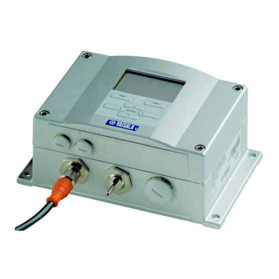
Outer Structure of the Barometer 503-001 Figure 1 Barometer Body Numbers refer to Figure 1 on page Signal + powering cable gland Pressure port Cable gland for optional module Cover LED Display with keypad (optional) Cover screw (4 pcs) VAISALA _______________________________________________________________________ 19... -
Page 22: Inner Structure Of The Barometer
User's Guide ______________________________________________________________________ Inner Structure of the Barometer 0705-091 Figure 2 Inside of Open Barometer Numbers refer to Figure 2 on page Adjustment button with indicator LED Power supply module (optional) Power supply mode selections Service port (RS-232) Module 1/Module 3 connectors User port Module 2/Module 4 connectors 20 __________________________________________________________________ M210855EN-C... -
Page 23: Chapter 3 Installation
The housing can be mounted either without the mounting plate or with optional mounting plates. Standard Mounting without Mounting Plate Mount the housing by fastening the barometer to the wall with 4 screws, for example M6 (not provided). VAISALA _______________________________________________________________________ 21... -
Page 24: Wall Mounting With Wall Mounting Kit
Standard Mounting Wall Mounting with Wall Mounting When mounting with wall mounting kit the mounting plate (Vaisala order code 214829) can be installed directly on wall or onto a standard wall box (also US junction box). When wiring through back wall, remove the plastic plug from the wiring hole in the barometer before mounting. -
Page 25: Mounting With Din Rail Installation Kit
Mounting with DIN Rail Installation DIN rail installation kit includes a wall mounting kit, 2 clip-fasteners and 2 screws M4 x 10 DIN 7985 (Vaisala order code 215094). Attach two spring holders to the plastic mounting plate by using the screws provided in the installation kit. -
Page 26: Pole Installation With Installation Kit For Pole Or Pipeline
Pole Installation with Installation Kit for Pole or Pipeline Installation kit for pole or pipeline (Vaisala order code: 215108) includes the metal mounting plate and 4 mounting nuts for pole mounting. When mounting, the arrow in the metal mounting plate must... -
Page 27: Figure 9 Horizontal Pole
Mount the plate to wall with 4 screws M8 (not provided) Fasten the barometer to the mounting plate with 4 fixing screws M6 (provided) Note the position of the arrow when mounting. This side must be up when mounting. VAISALA _______________________________________________________________________ 25... -
Page 28: Mounting Rain Shield With Installation Kit
Mounting Rain Shield with Installation Kit Numbers refer to Figure 12 on page 1 = Fasten the rain shield with installation kit (Vaisala order code: 215109) to the metal mounting plate with 2 (M6) mounting screws (provided). 2 = Fasten the mounting plate with rain shield with installation kit to the wall or to the pole (see pole installation). -
Page 29: Panel Mounting Frame
Panel Mounting Frame To enable a neat and dirt free embedded installation of the transmitter, a panel mounting frame is available as an option (Vaisala order code: 216038). The frame is a thin, flexible plastic frame for the transmitter, with adhesive tape on one side.The frame is used to hide any rough edges of the installation hole, and provide a more finished look. -
Page 30: General About Wiring And Grounding
User's Guide ______________________________________________________________________ 0703-068 Figure 14 Panel Mounting Dimensions General about Wiring and Grounding Cable Bushings A single electrical cable with a screen and three to ten wires is recommended for power and signal connections. The cable diameter should be 8...11 mm. The number of cable bushings depends on the barometer options. -
Page 31: Figure 15 Cable Bushings
NOTE When there is high electric noise level (for example, near powerful electric motor) in the operating environment it is recommended to use shielded cable or take care that the signal cables are separated from other cables. VAISALA _______________________________________________________________________ 29... -
Page 32: Grounding The Cables
User's Guide ______________________________________________________________________ Grounding the Cables Ground the screen of the electrical cable properly to achieve the best possible EMC performance. 0504-049 Figure 16 Grounding the Screen of Electrical Cable 30 __________________________________________________________________ M210855EN-C... -
Page 33: Grounding The Barometer Housing
When using basic wiring, see section Signal and Power Supply Wiring on page When using 8-pin connector, see section M-12 (8-Pin) Connector on page When using D-9 connector, see section D-9 Connector on page VAISALA _______________________________________________________________________ 31... -
Page 34: Signal And Power Supply Wiring
User's Guide ______________________________________________________________________ Signal and Power Supply Wiring When wiring the power supply module, see section AC Power Supply Module on page 0703-019 Figure 17 Screw Terminal Block on Motherboard Numbers refer to Figure 17 on page = Power control (0VDC = OFF, 5VDC = ON, if feature enabled) = User port (RS-232 terminals) = Power supply terminals 10 ... - Page 35 Close the cover and replace the cover screws. The barometer is ready for use. NOTE If you have chosen the external power control option you have to remove the wire between "Power control" and "Power +" -terminals prior to using the power control feature. VAISALA _______________________________________________________________________ 33...
-
Page 36: M-12 (8-Pin) Connector
User's Guide ______________________________________________________________________ M-12 (8-Pin) Connector 0503-026 Figure 18 Wiring of Optional M-12 (8-Pin) Connector Table 2 Pin Assignments to RS-232-/485 Serial Output Pin/Terminal Wire Serial Signal Analog Signal RS-232 (EIA-232) RS-485 (EIA-485) White Data out TX Brown (serial GND) (serial GND) Signal GND (for both channels) -
Page 37: D-9 Connector
Orange Supply voltage (10...30 Supply voltage (10...30 Supply VDC) VDC) NOTE The D-9 connector cannot be used with relay modules or power supply module that have AC (mains) power connection. NOTE The D-9 connector is not IP65 protection classified. VAISALA _______________________________________________________________________ 35... -
Page 38: Optional Modules
User's Guide ______________________________________________________________________ Optional Modules AC Power Supply Module The AC (mains) power connection may be connected to the power supply module only by an authorized electrician. A readily accessible disconnect device shall be incorporated in the fixed wiring. 0506-027 Figure 20 AC Power Supply Module Numbers refer to... -
Page 39: Installation
Do not detach the power supply module from the barometer when the power is on. WARNING Do not connect the mains power to power supply module when it is not installed in the barometer. WARNING Always connect protective ground terminal. VAISALA _______________________________________________________________________ 37... -
Page 40: Warnings
User's Guide ______________________________________________________________________ Warnings Dieses Produkt entspricht der Niederspannungsrichtlinie (73/23 EWG). Das Netzmodul darf nur von einem dazu befugten Elektriker angeschlossen werden. Trennen Sie das Netzmodul nicht vom Messwertgeber, wenn der Strom eingeschaltet ist. Verbinden Sie das Netzmodul nur mit der Spannungsquelle, wenn es im Messwertgeber PTB330 montiert ist. - Page 41 Voolukaabli võib vooluallika mooduli külge ühendada ainult volitatud elektrik. Ärge ühendage vooluallika moodulit saatja küljest lahti, kui vool on sisse lülitatud. Ärge ühendage voolukaablit vooluallika mooduli külge, kui seda pole PTB330-tüüpi saatjasse paigaldatud. Ühendage alati kaitsev maandusklemm! VAISALA _______________________________________________________________________ 39...
- Page 42 User's Guide ______________________________________________________________________ Ez a termék megfelel a Kisfeszültség villamos termékek irányelvnek (73/23/EGK). A hálózati feszültséget csak feljogosított elektrotechnikus csatlakoztathatja a tápegységmodulra. A bekapcsolt távadóról ne csatolja le a tápegységmodult. Ne csatlakoztassa a hálózati feszültséget a tápegységmodulhoz, ha az nincs beépítve a PTB330 távadóba.
-
Page 43: Galvanic Isolation For Output
This module prevents harmful grounding loops. NOTE Output isolation module is not needed when using the AC power supply module. 0703-006 Figure 21 Galvanic Output Isolation Number refers to Figure 21 on page Power Supply module VAISALA _______________________________________________________________________ 41... -
Page 44: Analog Output Module
User's Guide ______________________________________________________________________ Analog Output Module 0703-058 Figure 22 Analog Output 1 module Numbers refer to Figure 22 on page Flat cable pins Screw terminals for signal line DIP switches to select the output mode and range Installation and Wiring Disconnect the power. -
Page 45: Relay Module (Relay-1)
See the position in Figure 2, Inside of Open Barometer, on page 20 When the mains power is in use attach the grounding wire to the grounding terminal. VAISALA _______________________________________________________________________ 43... -
Page 46: Selecting The Activation State Of The Relay
User's Guide ______________________________________________________________________ Connect the flat cable between the relay module and the MODULE 3 pins of the motherboard. Take out the protective plug from the cable gland and thread the relay wires. Connect the wires to the screw terminals: NO, C, NC. See section Selecting the Activation State of the Relay on page Connect the power and close the cover. -
Page 47: Figure 24 Relay Module
The relay module may contain dangerous voltages even if the barometer power has been disconnected. Before opening the barometer you must switch off both the barometer and the voltage connected to the relay terminals. WARNING Do not connect the mains power to the relay unit. VAISALA _______________________________________________________________________ 45... -
Page 48: Rs-422/485-1 Interface Module
User's Guide ______________________________________________________________________ RS-422/485-1 Interface Module 0503-029 Figure 25 RS-485-1 Module Numbers refer to Figure 25 on page Flat cable pins Selection switches Screw terminals for wiring Installation and Wiring Disconnect the power. In case the RS-485-module is installed in the factory, continue with the item 4. -
Page 49: Table 4 Connecting The Twisted Pair Wires To The Screw Terminals
Table 4 Connecting the Twisted Pair Wires to the Screw Terminals Screw terminal Data line (2-wire RS-485) Data line (4-wire RS- 485/422) (not connected) (not connected) Data pair shield Data pair shield VAISALA _______________________________________________________________________ 47... -
Page 50: Figure 26 4-Wire Rs-485 Bus
User's Guide ______________________________________________________________________ 0708-014 Figure 26 4-Wire RS-485 Bus Table 5 4-Wire (Switch 3:On) RS-485 master Data PTB330 -> -> < - < - 48 __________________________________________________________________ M210855EN-C... -
Page 51: Figure 27 2-Wire Rs-485 Bus
Chapter 3 _______________________________________________________________ Installation 0708-015 Figure 27 2-Wire RS-485 Bus Table 6 2-Wire (Switch 3:Off) RS-485 master Data PTB330 <-> <-> VAISALA _______________________________________________________________________ 49... - Page 52 User's Guide ______________________________________________________________________ 50 __________________________________________________________________ M210855EN-C...
-
Page 53: Chapter 4 Operation
Basic Display Display shows you the measurement values of the selected quantities in the selected units. You can select 1... 4 quantities for the basic display. The basic display shows two quantities (P and P ) by default. VAISALA _______________________________________________________________________ 51... -
Page 54: Menus And Navigation
User's Guide ______________________________________________________________________ 0703-003 Figure 28 Basic Display Numbers refer to Figure 28 on page The Info shortcut key/left function button with guiding text The Graph shortcut button/right function button with guiding text Quantities selected for display. Note that units displayed (for example P) depend on the type of measurements. -
Page 55: Pressure 3H Trend And Tendency Reading
Trend (middlemost numeric value in the example), that is, pressure change during last 3 hours Pressure tendency graphics and codes The characteristic symbols of pressure tendency during the 3 hours preceding the time of observation are described as follows: VAISALA _______________________________________________________________________ 53... -
Page 56: Figure 31 Pressure Tendency Description
User's Guide ______________________________________________________________________ 0708-035 Figure 31 Pressure Tendency Description where: Increasing, then steady; or increasing, then increasing more slowly; atmospheric pressure now higher than three hours ago Increasing (steadily or unsteadily); atmospheric pressure now higher than three hours ago Decreasing or steady, then increasing; or increasing then increasing more rapidly;... -
Page 57: Using Serial Line
Press the NEXT button to have the trend graph and max/min graph in turns and browse through the quantities selected for display. Press the EXIT button to return to the basic display. VAISALA _______________________________________________________________________ 55... -
Page 58: Figure 32 Graphical Display
User's Guide ______________________________________________________________________ 0703-033 Figure 32 Graphical Display Trend graph: Displays a curve of average values. Each value is a calculated average over a period. Max/min graph: Displays the minimum and maximum values in a form of curve. Each value is max/min over a time period. See Table 7 below. -
Page 59: Information Display
Proceed in the information views by pressing the MORE button as many times as you get the desired information. You can browse through the information displays also with the arrow buttons. Press the OK button to return to the basic display. VAISALA _______________________________________________________________________ 57... -
Page 60: Display Settings
User's Guide ______________________________________________________________________ Display Settings Changing Quantities Open the MAIN MENU by pressing any of the arrow buttons. Select Display and press the right arrow button. Select Quantities and press the right arrow button. Select a quantity by using the up/down arrow buttons. Confirm your choice by pressing the SELECT button. -
Page 61: Rounding
This function locks the keypad and prevents unintentional button strokes. To lock the keypad, press and hold down the left function button for 4 seconds (at any display). To unlock the keypad, press and hold down the OPEN button for 4 seconds. VAISALA _______________________________________________________________________ 59... -
Page 62: Measuring Settings
User's Guide ______________________________________________________________________ Measuring Settings See the calculation formulas for pressure values in Appendix A, Calculation Formulas, on page 127. Open the MAIN MENU by pressing any of the arrow buttons. Select Measuring and press the right arrow button. Select Measuring settings. Press the right arrow button. Select an option with up/down arrow buttons. -
Page 63: Serial Interface Settings
Use the arrow buttons to select ECHO. Press ON to turn to it on. Press OFF to turn it off. 10. Press EXIT to return to the basic display. The new user port settings set using the display/keypad are effective immediately. VAISALA _______________________________________________________________________ 61... -
Page 64: System Settings
User's Guide ______________________________________________________________________ System Settings Language Open the MAIN MENU by pressing any of the arrow buttons. Select System (the lowest row), press the right arrow button. Select Language (marked with a flag symbol), press the SELECT button. Select the menu language with up/down arrow buttons and press the SELECT button. -
Page 65: Factory Settings
Select System by pressing the right arrow button. Select Clear graph memories by pressing the CLEAR button. Press the YES button to confirm the selection. CAUTION This function clears all the data history from the memory, all graphs included. VAISALA _______________________________________________________________________ 63... -
Page 66: Relay Settings
User's Guide ______________________________________________________________________ Relay Settings Relay Outputs 0705-185 Figure 35 Relay Indicators on Display The number refers to Figure 35 on page List enabled relays. Activation state is shown in black. Disabled relays are not shown. Use the display/keypad to set the relay outputs. Press any of the arrow buttons to open the MAIN MENU. -
Page 67: Testing The Operation Of Relays
Press OK to go back to normal operation. Select Test relay 2 to test the output of relay 2. Press ON/OFF to activate/deactive the output. Press OK to go back to normal operation. Press EXIT to return to the basic display. VAISALA _______________________________________________________________________ 65... -
Page 68: Analog Output Settings
User's Guide ______________________________________________________________________ Analog Output Settings Analog Output Quantities Use the display/keypad to change and scale the analog output quantities. Press any of the arrow buttons to open the MAIN MENU. Select Interfaces and press the right arrow button. Select Analog outputs and press the right arrow button. Select Output 1(P) and press the right arrow button. -
Page 69: Analog Output Fault Indication
Select Fault indication. Press the SET button. Enter the fault indication value by using the arrow buttons. Press the OK button to confirm your setting. This value is outputted if a barometer error occurs. Then press the EXIT button to return to the basic display. VAISALA _______________________________________________________________________ 67... -
Page 70: Mi70 Link Interface Software For Data Handling
MI70 link program also allows you to monitor barometer readings directly with a PC (real-time window function). The MI70 Link Interface Software is available from Vaisala. Connect the connection cable between the serial port of your PC and the Service Port of the barometer. -
Page 71: User Port Connection
Use suitable serial cable between the user port RxD, GND and TxD screw terminals and the PC serial port. Table 9 Default Serial Communication Settings for the User Port Parameter Value Bit rate 4800 Parity Even Data bits Stop bits Flow control None VAISALA _______________________________________________________________________ 69... -
Page 72: Figure 37 Connection Example Between Pc Serial Port And User Port
User's Guide ______________________________________________________________________ – POWER CONTROL 1 2 3 4 5 6 7 8 9 IOIOI 0506-033 Figure 37 Connection Example Between PC Serial Port and User Port Connections to pins 4,6,7 and 8 on PC serial port are required only if you are using software requiring hardware handshaking. -
Page 73: Service Port Connection
Select "File", and then "Save" in the HyperTerminal main window to save the serial port settings. To use the saved settings later, start HyperTerminal, click cancel in the "New Connection" window, and select "File". Then select "Open". VAISALA _______________________________________________________________________ 71... -
Page 74: Figure 38 Starting Hyper Terminal Connection
User's Guide ______________________________________________________________________ 0507-027 Figure 38 Starting Hyper Terminal Connection 0507-028 Figure 39 Connecting to Hyper Terminal 72 __________________________________________________________________ M210855EN-C... -
Page 75: List Of Serial Commands
Shows all unacknowledged errors (and clears them). HELP Shows the available commands. LOCK Shows or sets the keyboard lock. Outputs information on the device. ECHO [ON/OFF] Shows or sets the serial interface echoing. RESET Resets the device. VAISALA _______________________________________________________________________ 73... - Page 76 User's Guide ______________________________________________________________________ VERS Displays the product name and software version number. SNUM Shows the device and module serial numbers. Measurement commands Changes the serial mode to RUN and starts outputting measurement results according to the FORM string (with interval defined by INTV). INTV [0...255 s/min/h/d]Shows or sets the continuous output interval (for RUN mode).
- Page 77 Lists the available logs in the logging memory. PLAY Shows the trend, min and max values of the given log. Calibration and adjustment commands CDATE Shows or sets the calibration date. LCP1/ Performs a linear correction for the LCP2/ barometer module/module. LCP3 VAISALA _______________________________________________________________________ 75...
-
Page 78: General Settings
User's Guide ______________________________________________________________________ MPCP1/ Performs a multipoint correction for the MPCP2/ barometer module/module. MPCP3 CTEXT Shows or sets the calibration info text. NOTE The calibration and adjustment commands are available in adjustment mode only. Press the adjustment button before inputting these commands. -
Page 79: Using Serial Line
> Command ‘FORM /’ will return the default output format. The default output format depends on the device configuration. >form / Output format : P " " P1 " " QNH #RN >send 1004.95 1004.96 1004.95 > VAISALA _______________________________________________________________________ 77... -
Page 80: Unit
User's Guide ______________________________________________________________________ UNIT Use the UNIT command to display or set the output quantities and their units. Table 12 Output Quantities and Units Quantity Output Quantity Available Output Units Pressure (measures average hPa, psi, inHg, torr, bar, mbar, pressure from P , and P mmHg, kPa, Pa, mmH O, inH... -
Page 81: Measurement Related Commands
: 20.00 'C ? 21 > DPMAX The serial line command DPMAX shows or sets the maximum difference pressure allowed between barometer modules. The command is only available, if more than one barometer module has been installed. VAISALA _______________________________________________________________________ 79... -
Page 82: Hhcp
User's Guide ______________________________________________________________________ DPMAX [x] where Pressure Example: >dpmax 0.2 Max. diff. : 0.20 hPa > Use the AVRG command to set barometer measurement averaging time (in seconds). Valid range of averaging time is 1...600 seconds. AVRG [x] where Average time Example: >avrg Average filter : 1.0 s ? -
Page 83: Pstab
The settings can be changed one parameter at a time or all parameters at once: >seri 0 Baud P D S : 9600 N 8 1 >seri o Baud P D S : 9600 O 8 1 > VAISALA _______________________________________________________________________ 81... -
Page 84: Smode
User's Guide ______________________________________________________________________ SMODE Use the command SMODE to set the user port start-up operating mode. SMODE [xxxx] where xxx = STOP, RUN or POLL Table 13 Selection of Output Modes Mode Output Available Commands STOP Only with the SEND command All (default mode) Automatic output after power-up Only command S... -
Page 85: System Information Commands
: P #T P1 #T P2 #T DP12 #T QFE #RN Adjust. date : 2007-05-03 Adjust. info : VAISALA Date : 2007-05-08 Time : 13:42:01 Start mode : STOP Baud P D S : 4800 E 7 1 Output interval: 1 s VAISALA _______________________________________________________________________ 83... -
Page 86: Errs
User's Guide ______________________________________________________________________ Address Echo : ON Module 1 : BARO-1 Module 2 : BARO-1 Module 3 : BARO-1 Module 4 : EMPTY > ERRS Use the command ERRS to display all unacknowledged errors (and clear them). If an error is still active, it will be displayed again with the ERRS command. -
Page 87: Locking Menu/Keypad By Using Serial Line
INFO and GRAPH buttons. LOCK [x] where 1 (Menu locked) Example: >lock 1 Keyboard lock > Use the LOCK command to disable the keypad completely. LOCK [x] where 2 (Keypad disabled) VAISALA _______________________________________________________________________ 85... -
Page 88: Data Recording
User's Guide ______________________________________________________________________ Example: >lock 2 Keyboard lock > NOTE Open the locks with the serial command LOCK 0. You can open the menu lock also by using the keypad, if a PIN code has been set. Data Recording Data recording function is always on and collects data automatically into the memory of the device. -
Page 89: View Recorded Data
P1 latest 20 minutes 2000-01-08 03:44:31135 P1 latest 3 hours 2000-01-08 00:44:31135 P1 latest 1 day 2000-01-07 01:07:01135 10 P1 latest 10 days 1999-12-27 22:07:01135 11 P1 latest 2 months 1999-11-01 16:07:01135 12 P1 latest 1 year 1998-11-29 04:07:01135 > VAISALA _______________________________________________________________________ 87... -
Page 90: Play
User's Guide ______________________________________________________________________ PLAY Use the PLAY command to output the selected file to the serial line.The command outputs trend, min and max values from the given log. Use the DIR command to find out what log index number corresponds to a particular log. -
Page 91: Operation Of Relays
"below" value, the relay is passive when the measured value is not between the setpoints. You can also set only one setpoint. See Figure 41 on page 90 below for illustrative examples of the different measurement-based relay output modes. VAISALA _______________________________________________________________________ 89... -
Page 92: Hysteresis
User's Guide ______________________________________________________________________ 0610-076 Figure 41 Relay Output Modes Mode 4 is usually used if an alarm needs to be triggered when the measured value exceeds a safe range. The relay is active when measurement is in range, and is released if the value goes out of range or the measurement fails. -
Page 93: Relay Indicating Barometer Error Status
Live measurement (data available): relay active (C and NO outputs are closed) No live data (for example: error state or adjustment mode): relay released (C and NC outputs are closed). Figure 42 on page 92 below for illustrative examples of the FAULT/ONLINE STATUS relay output modes. VAISALA _______________________________________________________________________ 91... -
Page 94: Enabling/Disabling Relays
User's Guide ______________________________________________________________________ 0610-077 Figure 42 FAULT/ONLINE STATUS Relay Output Modes FAULT/ONLINE STATUS relays are usually used in conjunction with an analog output to obtain validity information for the output value. NOTE If a barometer loses its power, all status-based relays are released similarly to the case of an instrument failure. -
Page 95: Setting Relay Outputs
Rel1 P1 enabl: ON ? > Example of normal limit switch: Selecting relay 1 to follow pressure measurement and relay 2 to follow measurement of pressure from barometer module 1. One setpoint is chosen for both outputs. VAISALA _______________________________________________________________________ 93... -
Page 96: Testing Operation Of Relays
User's Guide ______________________________________________________________________ >rsel P P1 Rel1 P below: 980.00 hPa ? - Rel1 P above: 995.00 hPa ? 1020 Rel1 P hyst : 0.10 hPa ? 1 Rel1 P enabl: ON ? ON Rel1 P1 below: 1001.00 hPa ? --- Rel1 P1 above: 1005.00 hPa ? 1010 Rel1 P1... -
Page 97: Operation Of Rs-485 Module
(RS232 or RS485), or view currently set delay value. Value corresponds to tens of milliseconds (for example, 5 = 0.050s minimum answer delay). The value can be set between 0...254. Example: >sdelay Serial delay : 0 ? 10 >sdelay Serial delay : 10 ? VAISALA _______________________________________________________________________ 95... -
Page 98: Seri
User's Guide ______________________________________________________________________ SERI Use the SERI command to input RS-485 bus settings. SERI [b p d s] where bit rate (300, 600, 1200, 2400, 4800, 9600, 19200, 38400, 57600, 115200) parity (n = none, e = even, o = odd) data bits (7 or 8) stop bits (1 or 2) ECHO... -
Page 99: Intv
Setting RUN output interval to zero enables the fastest possible output rate. ADDR Addresses are required only for POLL mode (see serial line command SMODE on page 82). Use the ADDR command to input the RS-485 barometer address. VAISALA _______________________________________________________________________ 97... -
Page 100: Send
User's Guide ______________________________________________________________________ ADDR [aa] where aa = address (0 ... 255) (default = 0) Example: the barometer is configured to address 99. >ADDR Address : 2 ? > SEND Use the SEND command to output the reading once in POLL mode: SEND [aa] where aa =... -
Page 101: Close
Figure 22 on page 42 (DIP switches to select the output mode and range). Select the current/voltage output, switch ON either of the switches, 1 or 2. Select the range, switch ON one of the switches from 3 to 7. VAISALA _______________________________________________________________________ 99... -
Page 102: Figure 43 Current/Voltage Switches Of Output Modules
User's Guide ______________________________________________________________________ 0705-211 Figure 43 Current/Voltage Switches of Output Modules The number refers to Figure 43 on page 100: Current/voltage selection output switches (from 1 to 2) Current/voltage range selection switches (from 3 to 7) in analog output 1 and 2. Switch for service use only. -
Page 103: Analog Output Quantities
Table 1 on page Use the command ASEL [xxx yyy] as shown in the example below when using a device with two analog outputs. >asel P Ch1 P : 900.00 hPa Ch1 P high : 1100.00 hPa > VAISALA ______________________________________________________________________ 101... -
Page 104: Analog Output Tests
User's Guide ______________________________________________________________________ Analog Output Tests ATEST Use the serial line to set the analog output test value. The output value is forced to the inputted value and held until the command is fed without parameters. The number of quantities as parameters depends on the number of AOUT-1 modules. -
Page 105: Chapter 5 Maintenance
AERR or display/keypad to change this fault indication value, see section Analog Output Fault Indication Setting on page 102. the serial port outputs stars (***) the cover LED is blinking optional display: error indicator is lit. VAISALA ______________________________________________________________________ 103... -
Page 106: Figure 45 Error Indicator And Error Message
Internal barometer failure. Return the barometer to the Vaisala Service Center. Internal EEPROM write error. Internal barometer failure. Remove the barometer and return the faulty unit to Vaisala Service. E12...E15 Add-on module 1/2/3/4 connection Turn off the power and check the module failure connection. - Page 107 3) Check if the DPMAX value is set too low. E16...E19 Pressure measurement failure on Internal barometer failure. Return the barometer add-on module 1/2/3/4 to the Vaisala Service Center. Checksum error in the internal Internal barometer failure. Return the barometer configuration memory to the Vaisala Service Center.
- Page 108 User's Guide ______________________________________________________________________ 106 _________________________________________________________________ M210855EN-C...
-
Page 109: Calibration And Adjustment
Contact Vaisala Service Centers for details. It is recommended that calibration and adjustment should be carried out by Vaisala. See Vaisala Service Centers on page 125. -
Page 110: Opening And Closing The Adjustment Mode
User's Guide ______________________________________________________________________ NOTE Entering new linear or multipoint corrections will always cancel the previous corrections. It is advisable to write down the previous linear and multipoint corrections so that they will not be lost by mistake. Table 15 Adjustment and Calibration Commands for Barometer Module P1 Command Function... -
Page 111: Pressure Adjustment
2…8 pressure points. In such a case, the new adjustment values are entered to the multipoint adjustment function and the linear adjustment is not used (that is, it is left disabled). VAISALA ______________________________________________________________________ 109... -
Page 112: Adjustments Using Display/Keypad
User's Guide ______________________________________________________________________ Adjustments Using Display/Keypad Use the display/keypad to view the active multipoint/linear adjustments. Press the ADJ button located on the motherboard in the upper corner on the left-hand side to open the ADJUST PTB330 menu. Select P1 adjustments, press the right arrow button. Select Multipoint /Linear adjustment. -
Page 113: 1-Point Adjustment Using Serial Line
Each barometer module has its own adjustment commands. If there are three barometer modules installed, the commands LCP1, LCP2, and LCP3 will be available. First deactivate the previous corrections by using the LCP1 OFF command. VAISALA ______________________________________________________________________ 111... -
Page 114: Mpcp1
User's Guide ______________________________________________________________________ LCP1 [x/y] [z] where Example >lcp1 1. Reading ? 981.2 1. Reference ? 980.0 2. Reading ? 1102.1 2. Reference ? 1100.0 > NOTE The new linear corrections will always cancel the previous corrections as well as the valid date of calibration of the transmitter. MPCP1 Use the MPCP1 command. -
Page 115: Analog Output Adjustment (Ch1)
- current output: 2 mA and 18 mA - voltage output: 10 % and 90 % of the range Connect PTB330 to a calibrated current/voltage meter in order to measure either current or voltage depending on the selected output type. VAISALA ______________________________________________________________________ 113... -
Page 116: Using Display/Keypad
NOTE Normally, analog output module does not need to be adjusted once it has left from the factory. However, if accuracy of the unit is suspected, it is advisable to return the unit to Vaisala for re-adjustment/ calibration. Using Display/Keypad Press the ADJ button to open the ADJUSTMENT MENU. -
Page 117: Feeding Adjustment Information
CTEXT Use the CTEXT command to enter text to the adjustment information field. Example: >ctext Vaisala/MSL Calibration text : Vaisala/MSL > CDATE Use the CDATE command to enter date to adjustment information field. Set the adjustment date in format YYYY-MM-DD. - Page 118 User's Guide ______________________________________________________________________ 116 _________________________________________________________________ M210855EN-C...
-
Page 119: Chapter 7 Technical Data
Barometric pressure range 50 ... 1100 hPa Table 17 Barometric pressure range 50 ... 1100 hPa at 20°C Class B Linearity* ±0.20 hPa Hysteresis* ±0.08 hPa Repeatability* ±0.08 hPa Calibration uncertainty** ±0.15 hPa Accuracy at ±20 °C (+68 °F)*** ±0.20 hPa VAISALA ______________________________________________________________________ 117... -
Page 120: Operating Environment
User's Guide ______________________________________________________________________ Table 18 Temperature Dependence**** Class B 500 ... 1100 hPa ±0.01 hPa 50 ... 1100 hPa ±0.03 hPa Table 19 Total Accuracy at -40 ... +60°C (-40 ... +140 °F) Class A Class B 500 ... 1100 hPa ±0.15 hPa ±0.25 hPa 50 ... -
Page 121: Inputs And Outputs
Accuracy at -40 ... +60 °C ±0.60 hPa ±0.75 hPa Display LCD with backlight, graphic trend display of any parameter Menu languages English, German, French, Finnish, Spanish, Swedish, Japanese, Russian Power control 5 VDC to supply voltage VAISALA ______________________________________________________________________ 119... -
Page 122: Mechanics
User's Guide ______________________________________________________________________ Mechanics Table 23 Mechanics Cable bushing M20x1.5 For cable diameter 8...11mm/0.31..0.43" Conduit fitting 1/2”NPT Housing material G-AlSi 10 Mg (DIN 1725) Housing classification IP 65 (NEMA 4) User cable connector M12 series 8- pin (male) Option1 with plug (female) with 5m/16.4ft (optional) black cable Option2 with plug (female) with screw... -
Page 123: Table 26 Relay Module
4-wire (2-pair) full duplex Operating speed max 115.2 kbaud Bus isolation 300VDC Power consumption @ 24V max 50 mA External loads standard loads 32 RL> 10kohm Storage temperature range -55...+80 °C (-67...+176 °F) Max wire size 1.5 mm (AWG16 VAISALA ______________________________________________________________________ 121... -
Page 124: Options And Accessories
User's Guide ______________________________________________________________________ Options and Accessories Table 28 Options and Accessories Description Item Code MODULES Relay module RELAY-1L T-compensated analog output module AOUT-1T Isolated RS485 module RS485-1 Power Supply module POWER-1 AC-adapter MI70EUROADAPTER AC-adapter MI70USADAPTER AC-adapter MI70UKADAPTER AC-adapter MI70AUSDAPTER Static pressure head SPH10 Static pressure head SPH10... -
Page 125: Dimensions (In Mm)
0506-035 Figure 48 Barometer Body Dimensions Technical Support For technical questions, contact the Vaisala technical support: E-mail helpdesk@vaisala.com +358 9 8949 2790 If the product needs repair, please follow the instructions below to speed up the process and to avoid extra costs to you. -
Page 126: Return Instructions
Please include the Problem Report in the same box. Send the box to: Vaisala Oyj Contact person / Division Vanha Nurmijärventie 21 FIN-01670 Vantaa Finland or to the Vaisala Service Center in your region (see contact information below). 124 _________________________________________________________________ M210855EN-C... -
Page 127: Vaisala Service Centers
Chapter 7 ____________________________________________________________ Technical Data Vaisala Service Centers Vaisala Service Centers perform calibrations and adjustments as well as repair and spare part services, see contact information below. Vaisala Service Centers offer also extended services, for example accreditated calibrations, maintenance contracts and calibration reminder program. - Page 128 User's Guide ______________________________________________________________________ 126 _________________________________________________________________ M210855EN-C...
-
Page 129: Appendix Acalculation Formulas
This appendix contains the calculation formulas used by the product. Height compensated pressure values (QFE, QNH, and HCP) are calculated using the following equations: 0706-109 where: measured air pressure [hPa] height difference between the barometer and reference level [m] 9.81 [m/s2] 287 [J/kg/K] temperature [K] VAISALA ______________________________________________________________________ 127... - Page 130 User's Guide ______________________________________________________________________ 0706-110 where: station elevation [m] 9.81 [m/s 287 [J/kg/K] 288.15 [K] -0.0065 [K/m] 0706-111 where measured air pressure [hPa] height difference between the barometer and reference level [m] 128 _________________________________________________________________ M210855EN-C...
-
Page 131: Unit Conversion Tables
1.01325 0.980665 0.06894757 psia 0.01450377 0.00014504 0.01933678 0.4911541 0.001422334 0.036127 14.6962 14.2233 14.50377 Example 1013.25 hPa/mbar = 1013.25 x 0.02952999 inHg = 29.9213 inHg 0708-016 Figure 49 Pressure Conversion Chart * A unit not available on PTB330. VAISALA ______________________________________________________________________ 129... -
Page 132: Table 29 Unit Conversion Table For All Pressure Quantities
User's Guide ______________________________________________________________________ The device supports several different units for quantities. The following tables show the gain and offset values used for unit conversions. Table 29 Unit Conversion Table for all Pressure Quantities (Excluding deltaP and P Unit Gain Offset Min...Max 0 ... -
Page 133: Table 32 Unit Conversion Table For Settings Hhcp And Hqfe
Unit Conversion Table for Settings HQNH Unit Gain Offset Min...Max -30 ... 3000 3.28084 -99 ... 9900 Table 34 Unit Conversion Table for Setting TQFE Unit Gain Offset Min...Max °C -80 ... 200 °F -110 ... 390 -273.15 190 ... 470 VAISALA ______________________________________________________________________ 131... - Page 134 User's Guide ______________________________________________________________________ 132 _________________________________________________________________ M210855EN-C...
-
Page 135: Appendix Cpa11A Emulation Mode
R, and stop it with the command S. The command to output a single measurement message (P) is not available. To disable the emulation mode, set a different mode using the SMODE command (for example SMODE STOP), and reset the transmitter. VAISALA ______________________________________________________________________ 133... -
Page 136: Pa11A Message Format
User's Guide ______________________________________________________________________ PA11A Message Format Message type 1 format is as follows: <sp>P1<sp>P2<sp>P3<sp>status<sp>average<sp>trend<cr> where <sp> = Space character = Pressure output from transducer 1 (in 0.1 hPa). The reading is written with 5 characters. If the transducer has a fault or has been switched off, the reading is replaced with error status ///// = Pressure output from transducer 2, same format as P1... - Page 137 Pressure is 1008.4 hPa, output from transducer 2 is ignored, the three-hour trend is not available yet: 10084 ///// 10084 00000101 10084 /// Pressure is 1013.4 hPa and the three-hour trend is -0.4 hPa: 10134 10134 10134 10000000 10134 VAISALA ______________________________________________________________________ 135...
- Page 138 User's Guide ______________________________________________________________________ 136 _________________________________________________________________ M210855EN-C...
- Page 139 *M210855EN*...
Need help?
Do you have a question about the BAROCAP PTB330 and is the answer not in the manual?
Questions and answers