
Subscribe to Our Youtube Channel
Related Manuals for Teac GX-1


Summary of Contents for Teac GX-1
- Page 1 INTEGRATED RECORDER GX-1 Instruction Manual Please read this manual before using the product, and keep this manual handy. TEAC Corporation May 2002 D00458510C...
-
Page 2: Safety Instructions
SAFETY INSTRUCTIONS 12) Power-Cord Protection — Power-supply cords should CAUTION: • Read all of these Instructions. be routed so that they are not likely to be walked on or pinched • Save these Instructions for later use. by items placed upon or against them, paying particular atten- •... - Page 3 MO type, and PC card type. Before reading the ed in a commercial environment. This equipment manual, make sure which type your GX-1 belongs generates, uses, and can radiate radio frequency to. AIT tapes, MO disks, and PC cards are general- energy and, if not installed and used in accordance ly termed as “removable media”...
-
Page 4: Table Of Contents
Features ....... . . 1-4 Specifications for the GX-1 Main Unit ..4-4 About TAFFmat . - Page 6 Introduction Overview....... . . 1-3 Features ....... . . 1-4 About TAFFmat .
-
Page 8: Introduction
Recorded data can be saved to files for a PC in a TEAC unique format called TAFFmat, and can be opened and processed using commercially available analytical PC software. -
Page 9: Features
Introduction Features Selectable recording medium that best matches what Voice memo recording/playback you record You can record and play back voice memos. A choice of recording media allows you to select the medi- External-clock sampling um that best matches the application, like choosing memory when recording fast phenomena and choosing an AIT or MO Sampling can be performed based on an external clock sig- drive when recording a great amount of data. - Page 10 Introduction Sampling Frequency and Monitoring (Up to 32 channels) Sampling frequency ≤ 20 kHz 200 kHz 100 kHz 50 kHz Waveform Manual start recording ∆ Level trigger recording — Reproducing — Manual start recording — — ∆ Level trigger recording —...
-
Page 11: About Taffmat
A collection of data recorded from the hand. Do not pull the cord. start until the end of each measurement by a GX-1 is referred to as an ID. Each ID is composed of one data file and one header file. -
Page 12: Name Of Each Part
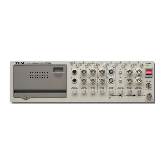
Introduction Name of Each Part Front Panel <1> <2> <3> <4> <8> <7> <6> <5> <1> Recording device slot <5> Monitor output connector The slot into which an AIT drive, MO drive, or PC card slot The jack used to output the analog signal of a selected chan- is installed. -
Page 13: Rear Panel
<3> Cooling fan <8> DK-GXLCD connector Connect the dedicated cable to the TO GX-1 connector on An exhaust fan for cooling the GX-1 main unit. Do not block the exhaust vent. the LCD controller when you record a voice memo with a microphone connected to the controller. -
Page 14: Right Side Panel
Introduction Right Side Panel <1> <2> <1> Power supply slot The slot into which an AC adaptor or battery pack is to be installed. <2> Eject lever Push this lever when removing an inserted AC adaptor or battery pack. The AC adaptor or battery pack pops out by the force of a built-in spring—be careful not to hurt yourself or drop it. - Page 15 1-10...
-
Page 16: Installation
Installation Installing Amplifiers ......2-3 Attaching the Handle ..... . . 2-4 Adding the Expansion Unit . -
Page 18: Installing Amplifiers
(See fig. 2.) Channel Numbers Slots are numbered from the left (as viewed from the front of the GX-1 main unit) in the order 1, 2, 3, etc. These corre- within within spond to channels 1 and 2, channels 3 and 4, etc. -
Page 19: Attaching The Handles
Attaching the Handles Remove the screws and washers from both sides of the GX- CAUTION 1. (Two from each side) Hold both handles to carry the GX-1. Do not carry it Mount the handles with the provided screws by holding one handle. -
Page 20: Adding The Expansion Unit
Use the dedicated cable to connect the BUS OUT connector at 1 unit added 2 units added 3 units added the rear of the GX-1 main unit to the BUS IN connector at the rear of the expansion unit. To add more expansion units, daisy- 1st exp. - Page 21 To install the AC adaptor: mended when the DC power supply is unstable. Also in this case, if the supply voltage drops to +10 V or less, the GX-1 Confirm that the power is turned off at the GX-1 main unit: automatically shuts down.
-
Page 22: Preparing A Personal Computer
Set a number from 0 to 6. If one or more SCSI devices are then turn on the power to the GX-1 main unit again, the PC will connected to the PC, make sure you set a unique ID. All the be unable to recognize the GX-1. -
Page 23: About Ait Cartridge
About AIT Cartridge Inserting an AIT Cartridge To insert an AIT cartridge: Turn on the power to the GX-1 main unit. The buzzer will sound three pairs of beeps. Open the door to the AIT drive. Insert the AIT cartridge. - Page 24 (SONY SDX1-CL) to clean the head once every fifty hours of operation. To clean the head, turn on the power to the GX-1 and insert the cleaning tape into the drive. The drive will automatically perform cleaning and eject the tape after the cleaning is com- pleted.
-
Page 25: About Mo Disk
Write-protect MO Disk Remove the MO disk before turning off the power to the GX-1. If you turn off the power while the drive is Write-protect an MO disk in which data is recorded before you writing, the data recorded on that MO disk might insert it into a PC’s external MO drive. -
Page 26: About Pc Card
STOP mode or the power is turned off. a result, the data become unreadable by PC or GX-1. Otherwise, the data recorded on that PC card might become unreadable. - Page 27 2-12...
-
Page 28: Gx Navi
GX Navi... -
Page 30: Basic Operations
Basic Operations The Initial Window ......3-4 Operation Flow ......3-5 Recording to Memory, Then Transferring to PC . -
Page 31: The Initial Window
Basic Operations The Initial Window When the attached software “GX Navi” starts, the following window is displayed. Exit software that eats a lot of memory before you run the “GX Navi”. Main toolbar: Contains buttons for file operations and settings. Control toolbar: Contains buttons for recording/reproducing operations. -
Page 32: Operation Flow
Basic Operations Operation Flow From the initial window, follow the flow below. Other procedures may cause malfunction. Initial Window Waveform display Data transfer File name/condition setting Recording of data in memory after recording File setting Select waveform Select waveform Data transfer display display [File]—[New]... -
Page 33: Recording To Memory, Then Transferring To Pc
Basic Operations Recording to Memory, Then Transferring to PC The following procedure illustrates how to record two IDs in memory and to transfer Before actual recording, set the recording con- the data to a PC after recording stops. The procedure also illustrates how to attach an ditions following the steps illustrated in the pre- vious page. - Page 34 In this case, the data is not transferred Do not do the following operations during recording (during to the PC, but remains in the GX-1’s memory. REC STANDBY, RECORDING, or REC PAUSE) as they You can transfer the data to the PC’s another may cause system instability: drive by choosing Edit and then Copy.
-
Page 35: Recording To Removable Medium
Basic Operations Recording to Removable Medium The following procedure illustrates how to record two IDs to AIT/MO/PC card. The Before actual recording, set the recording con- ditions following the steps illustrated in the procedure also illustrates how to attach an event mark to a desired location in the page 3-5. - Page 36 Basic Operations The number of scans at this moment is recorded Click the Event button ( in the header file. There must be at least two seconds between The Number of IDs area displays 001-001. event marks. No event mark is attached if the time is less than two seconds.
-
Page 37: Copying From Removable Medium To A Pc
Basic Operations Copying from Removable Medium to a PC To copy the data recorded on AIT/MO/PC card to a PC, proceed as follows: From the Edit menu, choose Copy. The following window appears: Do not eject a removable medium during copy- ing even if it is not the source or destination. -
Page 38: The Waveform Display Window
Basic Operations The Waveform Display Window The Waveform Display window is composed of the components described below. It may be some time before the waveform After data is recorded in memory, this window displays the data in memory. You can appears after recording stop. - Page 39 Basic Operations Time Axis for the Waveform Display, and Sampling Frequency Time axis settings Sampling frequency 50 mS 100 ms 200 ms 500 ms 10 s 20 s 50 s 100 s Note 1 Hz — *1 — *1 — *1 —...
-
Page 40: The Fft Window
Basic Operations The FFT Window The FFT window has the functions described below. To switch from the Waveform Display window or the Bar Graph window to the FFT FFT display is possible when the sampling fre- quency is 50 kHz or lower. window, from the View menu choose FFT Monitor, or click the button. -
Page 41: The Bar Graph Window
Basic Operations The Bar Graph Window The Bar Graph window has the functions described below. To switch from the Waveform Display window or the FFT window to the Bar Graph Bar graph display is possible when the sam- pling frequency is 50 kHz or lower. window, from the View menu choose Bar Graph, or click the button. -
Page 42: Reproducing
Basic Operations Reproducing Data recorded in the internal device — memory or removable medium — can be repro- The data recorded in a medium on the PC can- not be reproduced. duced in waveform display. With the optional analog output amplifier, you can reproduce the recorded data as analog sig- nal. - Page 43 Basic Operations When reproducing data recorded at a low sam- Click the Start button ( ) to start reproducing. pling frequency, it may take some time until the waveform appears. Please note that, if the Click the Stop button ( recording time is short, the reproduction may ) to make reproducing pause.
- Page 44 Basic Operations Reproduction at a Speed Different from the Recording Speed You can select a sampling frequency at reproduction that is different from the sampling frequency at recording. After selecting the file to be reproduced, from the Setup menu choose Params, and then change the Base Sample setting.
-
Page 45: Using The Remote Controller
Use the dedicated cable to connect the remote controller to the ER-GXRC connector at the rear of the GX-1. Note: It does not matter whether the power to the GX-1 is turned on before or after you connect the remote controller. Functions of Each Button... - Page 46 When ON/OFF is Selected eject button on the drive is unusable. In this mode, you can control GX-1 recording by using the ER- GXRC only (Stand Alone is ON). Control is also possible from • The catalog information for AIT recording is recorded in a GX Navi;...
- Page 47 3-20...
-
Page 48: Explanations Of Menus
Explanations of Menus ..........3-22 ..........3-23 ..........3-23 ..........3-23 ..........3-23 ..........3-23 ..........3-24 ..........3-24 ..........3-24 ..........3-25 ..........3-25 ..........3-25 ..........3-26 ..........3-26 ..........3-31 ..........3-31 ..........3-34 ..........3-34 ..........3-35 .......... -
Page 49: The File Menu
4. When Realtime is selected, the recorded data is transferred directly to the PC Real-time transfer is possible when the the media without going through the GX-1 internal memory—real-time transfer. recording rate—sampling frequency multiplied In real-time transfer, however, following functions are disabled: by number of channels—is 1500 k data/s or... - Page 50 Explanations of Menus 5. When File number auto increment is selected, the 3-digit ID number append- Even if the File number auto increment option is not selected, the ID number will be ed to the filename is automatically incremented whenever recording is restarted after a STOP (or after a pause).
- Page 51 Reset Setting Data Resets the Setup menu's System, Misc, or Params settings. Also resets the set- tings stored in the memory of the GX-1 main unit. To start recording just after reset- ting, click ALL on the channel select palette.
-
Page 52: The Edit Menu
Explanations of Menus Exit Terminates the application. The Edit Menu Zoom Enlarges part of a displayed waveform after data is recorded. While pressing the left button, drag the mouse pointer through the area that you want to enlarge; the area will be highlighted. -
Page 53: The Setup Menu
Details of each mode are explained on the next page. 2. IRIG When IRIG displays ON, at the start of recording the GX-1 internal clock is cor- rected by an IRIG-B time code input through the DIGITAL CONTROL connec- When you select 1,024 for Count, the sampling tor. - Page 54 Explanations of Menus About voice memo recording/playback There are three types of modes for recording voice memo: MIX: Voices are sampled at the same sampling frequency as Rec Standby Rec Start Stop data. Set the sampling frequency to higher than 5 kHz Data Normal to listen to the voice.
- Page 55 Explanations of Menus 4. Pre/Post Trigger When the option Pre/Post Trigger is selected, the Pre-trigger or Post-trigger Pre/Post Trigger can be used in conjunction with Trigger Rec, which is explained next. recording mode can be selected. Select either the P r e T r i g g e r or PostTrigger option, and select Second or Scan in the rightmost box to deter- The possible pre-trigger time depends on the amount of memory, the sampling frequency,...
- Page 56 Explanations of Menus 5. Trigger Rec The Trigger Rec settings can be used in con- junction with the previously described When the option Trigger Rec is selected, recording starts when the specified Pre/Post Trigger settings. channel signal level changes to the trigger level. When the system enters the You can set the time from the start to the end of Record Standby status, the level begins to be monitored and recording starts when recording by clicking the Repeat button and...
- Page 57 Explanations of Menus 8. Timer Rec When the option Timer Rec is selected, the GX-1 internal clock is set to timer activity. Timer Rec can be used in conjunction with If Single is selected, the starting or stopping of recording at the specified time is the previously described Pre/Post Trigger settings.
- Page 58 Once you perform recording with the fan stopped, wait five minutes before you resume 1. The Fan setting can stop the GX-1 cooling fan for five minutes from the start of recording. recording. This is convenient when taking sound measurements. The fan does not Do not stop the fan in Post Trigger mode, stop during REC STANDBY.
- Page 59 File box (3). If you then click OK in the Parameters window, the contents of the file will be set in the GX-1 main unit. 4. Base Sample Freq The Base Sample Freq entry determines the sampling frequency common to all...
- Page 60 Explanations of Menus To sweep external sampling clock When you choose External from Base Sample Freq, Sweep check box will appear. Check the box to sweep the external sampling clock. If not checked, the input frequency must be constant. Note the following when sweeping the sampling clock. •...
- Page 61 Loads the .gxs file. Before loading, insert the same medium that was used when the gxs file was saved into the same slot. The settings in this file are set in the GX-1 Loading may take some time depending on the contents of the file to be loaded.
-
Page 62: The View Menu
Explanations of Menus The View Menu Toolbar Selects the toolbar to be displayed. Selecting the name of a toolbar adds a check mark in front of the name. Copy System Params Main: Open Zoom Print Misc Back to the head of the previous ID (effective during stop of reproducing) In Recording: Rec Stop In Reproducing: click once: Rep Pause, click twice: Rep Stop Start... -
Page 63: Status Bar
Explanations of Menus Status Bar Displays or hides the status bar at the bottom of the window. Wave Monitor : Switches the display to the Waveform Display window. FFT Monitor : Switches the display to the FFT window. Bar Graph : Switches the display to the Bar Graph window. - Page 64 Explanations of Menus Wave Panel Displays the panel to show the digital value of the waveform. Selectable only when the waveform display is selected. The value at the left end—not at the cur- sor—of the waveform of the specified channel is displayed. Displays digital value.
-
Page 65: The Window Menu
Explanations of Menus Channel Select Displays the Channel Select Palette. Selects the channel to be displayed. The CAN input amps are selected slot by slot. Displays all channels. Switches between each set of 16 channels when using expanded channels. The Window Menu Cascade When multiple windows are open, this menu command displays the windows in a partly overlapping format. - Page 66 Explanations of Menus About Auto Range You can automatically optimize the input ranges for analog type amplifiers. The input ranges of all channels of the analog type amplifiers are optimized at a time. • You cannot use this function when the sampling frequency (the higher frequency in multi-sampling) is higher than 50 kHz or when you sweep the external sampling clock.
- Page 67 3-40...
-
Page 68: Technical Information
Technical Information... -
Page 70: Specifications
Specifications Specifications for the GX-1 Main Unit ..4-4 Block Diagram ......4-5 File Formats . -
Page 71: Specifications For The Gx-1 Main Unit
Specifications Specifications for the GX-1 Main Unit Signal conditioner slots : Recording device slot : 1 (for AIT drive) Memory : DIMM 32—256 MB Interface : SCSI (connector 50-pin half size x 1, built-in terminator) Contact-point control : START, STOP, EVENT, REC STANDBY... -
Page 72: Block Diagram
Specifications Block Diagram... -
Page 73: File Formats
PC. On an AIT cartridge, however, the data is is appended to the last channel data of each sampling. stored in a TEAC unique format. To utilize the data on an AIT, you can use GX Navi to copy the data as a TAFFmat... - Page 74 Specifications Example 2 The illustration below shows a scan of data recorded at a sampling frequency of: • 1 kHz for channels 1 and 2 • 10 kHz for channels 3 and 4 The illustration below shows the sample timing for this exam- •...
- Page 75 Specifications Example 3 The illustration below shows a scan of data recorded at a sampling frequency of: • 1 kHz for channels 1 and 2 • 10 kHz for channels 3 and 4 • 1 kHz for channels 5 and 6 •...
-
Page 76: Header File
SERIES CH3_AR-GXDC, CH4_AR-GXDC, CH9_AR-GXDC, CH10_AR-GXDC, MEMO DATE 02-02-2000 TIME 15:52:17.00 RATE 5000 VERT_UNITS V , V , V , V , V HORZ_UNITS Sec COMMENT <<< TEAC GX-1 >>> NUM_SERIES 5 STORAGE_MODE INTERLACED FILE_TYPE INTEGER SLOPE 0.00004000, 0.00004000, 0.00004000, 0.00004000, 0.00004000 X_OFFSET 0 Y_OFFSET 0.0, 0.0, 0.0, 0.0, 0.0... - Page 77 DATA : Indicates that the following information is unique to this device and is differ- ent from the DADiSP format. DEVICE : Fixed at GX-1. CH1_ : Channel number, type of amplifier, range setting, and filter setting follow the under bar.
-
Page 78: Connector Specifications
Specifications Connector Specifications SCSI Connector DIGITAL CONTROL Connector Connector on GX-1 main unit : DX10G1M-36 from Hirose Electric Co., Connector on GX-1 main unit : NHS050-022-BS2 from Ltd. Yamaichi Electronics Co., Ltd. Mating plug : DX40M-36P(03) from Hirose Electric Co., Ltd. -
Page 79: External Dimensions
Specifications External Dimensions Unit: mm 4-12... - Page 80 4-13...
- Page 81 4-14...
-
Page 82: Amplifiers
Amplifiers DC Input Amp (AR-GXDC) ....4-16 Microphone Input Amp (AR-GXMC) ... 4-18 Dynamic Strain Input Amp (AR-GXST) . -
Page 83: Dc Input Amp (Ar-Gxdc)
Amplifiers DC Input Amp (AR-GXDC) The AR-GXDC is an amp for inputting signals converted to voltages. Filters Analog Filter The analog filter is an 8th order Butterworth low-pass filter (–48 dB/oct). The cutoff frequency can be selected independently of the sampling frequency. - Page 84 Amplifiers Specifications Number of channels : Input format : Unbalanced Input coupling : Input impedance : 100 kΩ Input range : ±0.5, 1, 2, 5, 10, 20 Vp Range accuracy: ±1% or better Frequency response : DC to 80 kHz (±1.5 dB) Low pass filter : 2, 4, 8, 20, 40, 80, 200, 400, 800 Hz, 2 k, 4 k, 8 k, 20 k, 40 k, 80 kHz...
-
Page 85: Microphone Input Amp (Ar-Gxmc)
Amplifiers Microphone Input Amp (AR-GXMC) The AR-GXMC is an amp for connecting a microphone used for mea- surements. Filters Weighting Filter This is an analog weighting filter (A, C) that conforms to IEC TYPE1 class. Analog Low-Pass Filter Has an analog low-pass filter to prevent aliasing, with that cutoff fre- quency automatically determined when the sampling frequency is selected. - Page 86 Amplifiers Specifications Number of channels : WARNING Input format : Unbalanced Do not insert objects, such as metallic Input coupling : pins, in the input connector of the micro- Input impedance : 11 kΩ phone input amp. A high voltage is out- Applicable microphone : B&K (only for 50 mV/Pa type) put so electric shock might result.
-
Page 87: Recommended Microphones
There are various types of piston phones, but piston phone case, consider the value to be just an estimate. calibration of the GX-1 is limited to the following: 250 Hz to 1 kHz, and 94, 114, and 124 dBSPL. The correction value is a temporary numeric value used at... - Page 88 Sound is a compressional wave, and microphone output is a verted to an AD value of 25000. plus value in a dense location, and a minus value in a sparse location. Data recorded to GX-1 is unchanged instantaneous The instantaneous sound pressure value (Pa) is the AD value values.
-
Page 89: Dynamic Strain Input Amp (Ar-Gxst)
±1400 µST. numerically the same (making the situation easy to under- When a sensor and the GX-1 are separated by a long dis- stand), a excitation voltage of 2 V is often used. For example, when ε = 1000 µST (µST: micro strain. A strain tance, the lowered excitation voltages can affect measure- ments. - Page 90 Zero Balancing Perform zero balancing each time you turn on power to the GX-1. To perform zero balancing, in the parameter settings dialog box click the Exec button. When you select All Strain Amp and click Exec, zero balancing will be simultaneously performed on all channels in the dynamic strain input amp.
- Page 91 Amplifiers Connect the cables from the sensors to the input con- nectors before turning on the power of the GX-1. Specifications Otherwise, the precision may be lowered. Number of channels : Input format : Balanced difference input Pin assignment for input connector...
- Page 92 Zero Balancing Click Exec to perform zero balancing whenever the GX-1 is powered on. After selecting the option All Strain Amp and clicking Exec, zero balancing is performed simultaneously on all channels on the installed dynamic strain input amps.
-
Page 93: Thermocouple Input Amp (Ar-Gxtck/J)
The digital filter using a DSP can attenuate from 40% of sure to a comparatively low temperature. With the GX-1, the set sampling frequency. The digital filter is not func- the lower temperature range of both is down to –50˚C. - Page 94 Amplifiers Specifications Number of channels : Applicable thermocouple : K (AR-GXTCK), J (AR-GXTCJ) Zero point compensation : Electronic Range : AR-GXTCK : –50 to 300, –50 to 600, –50 to 1200˚C AR-GXTCJ : –50 to 150, –50 to 300, –50 to 600˚C Range accuracy : 1%FS±3˚C (–50 to 150˚C, –50 to 300˚C) 0.5%FS±3˚C (–50 to 600˚C, –50 to 1200˚C)
-
Page 95: F/V Input Amp (Ar-Gxfv)
Amplifiers F/V Input Amp (AR-GXFV) When analyzing the behavior of revolving bodies, such as in engines or turbines, you sometimes need to record signals corresponding to the number of revolutions. The AR-GXFV converts into voltages the fre- quency of the pulses issued according to the revolutions, and records the resulting values. - Page 96 Amplifiers Settings The following dialog box appears when you choose Setup and Params, and then double-click the channel that you want to set. Channel : Select ENABLE to record with this channel, or select DISABLE not to record with this channel. Enable both channels of a slot. Sample Frequency : You can select 10 times the Base Sample Freq when you turn on Multi Sampling check box.
-
Page 97: Charge Amp (Ar-Gxch)
Amplifiers Charge Amp (AR-GXCH) When pressure is applied to certain crystals, electrical polarization occurs. This phenomenon is called a piezoelectric effect. From among the acceleration transducers that use this piezoelectric effect, the elec- trical-charge output type transducers are connected to the AR-GXCH. In the SI system of units, the unit of acceleration is m/s2. - Page 98 Amplifiers Specifications Number of channels : Electric charge sensitivity : 0.1 to 999 pC/G 1 G = 9.81 m/s Range : 1, 5, 10, 50, 100, 500 G (100 G and the 500 G range cannot be used when the electric charge sensitivity is 100 pC/G or higher) (1 G and the 5 G range cannot be used when the electric charge sensitivity is lower than 1 pC/G) Range accuracy* :...
-
Page 99: Pulse Input Amp (Ar-Gxpc)
Amplifiers Pulse Input Amp (AR-GXPC) Like the AR-GXFV, the AR-GXPC inputs pulse signals from sources such as a revolving body; however, the AR-GXFV converts pulses to voltages whereas the GR-GXPC counts pulses directly. Available modes include the Total Mode in which the total number of pulses is recorded, and the Gate Mode in which the number of pulses in a speci- fied gate period are counted. - Page 100 Amplifiers Specifications Number of channels : Input format : Insulated by photocoupler Input voltage range : 4—10 V/8—24 V (8 mA or more input current required) Responsive frequency : 2 MHz max. Sampling frequency : 1 Hz to 200 kHz Counting method : Division rate: 1/1 to 1/255 Count: 0 to 32767 (16 bits with a sign)
-
Page 101: Dc/Icp Input Amp (Ar-Gxpa)
Amplifiers DC/ICP Input Amp (AR-GXPA) Like the charge amp AR-GXCH, the AR-GXPA connects to an accel- eration transducer that uses the piezoelectric effect; however, the AR- GXPA connects to a transducer that has a built-in preamp to convert the charge to voltage and lower the circuit resistance. The AR-GXPA provides a constant current source (0.5 mA, 3 mA, and 5 mA) to this preamp. - Page 102 Amplifiers Specifications Number of channels : Input format : Unbalanced Input coupling : DC (DC mode)/AC (PA mode) DC mode: Not supply power to the sensors. Input impedance : 100 kΩ PA mode: supplies power to the sensors. Input range : ±0.5, 1, 2, 5, 10, 20 Vp (DC mode) When you record in the PA mode for the first time ±0.1, 0.2, 0.5, 1, 2, 5, 10, 20 Vp (PA mode)
-
Page 103: Digital Input/Output Amp (Ar-Gxdio)
Amplifiers Digital Input/Output Amp (AR-GXDIO) The AR-GXDIO amp is for recording and playback of 16-bit digital signals. When used as an output amp, analog signals input into anoth- er channel can be output as a digital signal. When used as an input amp, engineering implications can be added to recorded data. - Page 104 Amplifiers Specifications Number of channels : Input format : CMOS level, 16 bits each channel Output format : Open drain, 16 bits each channel Input/Output switching: Slot by slot Sampling frequency : 1 Hz to 200 kHz Trigger: AND/OR selectable for specified bits Input/Output connector : JAE TX20A-36R-D2LT1-A1LH (amp side) A connector and a cable attached (one end stripped)
- Page 105 Amplifiers Digital Monitor The waveform display for the digital input/output amp shows High/Low of each bit as shown below: The value is displayed in hexadecimal. Digital Input Trigger Setting High/Low change of specified bits of digital input channel can trigger recording. To set trigger conditions, click the channel of digital input/output amp on Trigger Rec box and and then click Digital I/O.
- Page 106 Amplifiers Input/Output Circuit +5 V 47 kΩ 74LVC14 1 kΩ IOA1—16 IOB1—16 74HC05 IOSTB 74HC05 Input/Output Timing (at connector) IOSTB min.100 nsec min.30 nsec IOA1—16 INPUT IOB1—16 max.100 nsec min.100 nsec IOA1—16 OUTPUT IOB1—16 Note: IOSTB should be pulled-up externally. Relation between sampling frequency and IOSTB Sampling frequency...
- Page 107 Amplifiers Pin Assignment and Wire Color of Attached Cable Pin Signal name Function Wire color Pin Signal name Function Wire color IOA1 A channel IO1 Orange (1 black dot) IOB1 B channel IO1 Orange (1 red dot) IOA2 A channel IO2 Gray (1 black dot) IOB2...
-
Page 108: Analog Output Amp (Ar-Gxao)
Amplifiers Analog Output Amp (AR-GXAO) Specifications Number of channels : Analog output amplifiers must be installed in Output format : Unbalanced the slots following the slots in which input amplifiers are installed. Output coupling : Output range : ±1 to 5 Vp (variable in 0.1 V steps) The maximum output voltage is approx. -
Page 109: Can Input Amp (Ar-Gxcan)
(Page 4-46) Number of recording bus ports: 1 port/card The GX-1 recognizes the CAN input amp as an A/B 2-channel amp. You can install a maxi- Supported CAN bus standards: Supported standards include the following CAN mum of 2 CAN input amps. - Page 110 Amplifiers Settings The following dialog box appears when you choose Setup and Params, and then double-click the channel that you want to set. This amp does not support the listen-only mode. So care is required because, if the Baud rate set- ting differs from the Baud rate of the connected bus, an error frame might be issued and the bus for the sending node might be set to off...
- Page 111 Amplifiers CAN Data Monitor During recording, the CAN data monitor can monitor and dis- The CAN ID Dialog Box in Normal Mode play the ID, data length and data (hexadecimal). In the channel The dialog box displays the data for a specified ID. selection palette, you specify that the CAN board data is to be displayed, and click the CAN monitor button in the tool-...
- Page 112 GX-1 lowest sampling frequency, and set that value (or as illustrated below, an approximation of that value). If the GX-1 data transmission (1 frame for 4 samplings) is faster than the time for one transmission by a CAN bus data frame, frames will not be dropped.
- Page 113 Amplifiers Arrangement of Transceiver Cable Pins Recommended transceiver cables are from KVASER Inc. Pin No. DRVcan 251/1053 TYPE DRVcan S Not connected. Not connected CAN_L (low level @ dominant) Not connected Not connected. Not connected D-sub connector on the transceiver Shield Shield Not connected.
- Page 114 Original file you specify the source file to be converted (the file with the status read from GX-1), and in Output file you specify the output file. In Format type of output file, you specify CAN File.
- Page 115 Amplifiers To specify the output data, in Channel of original file select the data that you want to output, and click the Add button. The method for selecting the CAN data label is described below. The Channel of original file area displays the CAN channel (CH1_AR_GXCAN in the example on the previous page), so double-click that channel.
-
Page 116: Appendix
Appendix In Case of Trouble......5-3 Index ........5-4 Supplied Accessories . -
Page 118: In Case Of Trouble
If system hangs with AIT inside To reset the GX-1 if it hangs up, proceed as follows: If the system hangs up with the AIT in the drive, reset the GX-1 following the steps below: Quit the attached software “GX Navi” and turn off the power of the GX-1. -
Page 119: Index
Appendix Index On GX Navi screen Wave Panel........3-37 Window ..........3-38 Zoom ..........3-25 AIT............2-8 Auto Range ........3-39 Amplifiers, installing ......2-3 Bar Graph...........3-14 Bar graph window ......3-14 Base Sample Freq ......3-32 Model name Block diagram ........4-5 Cascade ..........3-38 Clock adjustment........3-31 Change Unit ........3-34 Copy..........3-10, 3-25 Channel Select........3-38 AR-GXAO...........4-41... -
Page 120: Supplied Accessories
Appendix Supplied Accessories Separately Purchasable Options GX-1 AIT cartridges (SONY SDX1-25C) AIT cleaning tape (SONY SDX1-CL) AC power cable PC adaptor board (TZ-GXPAB) 3P-2P adaptor* ST input cable type 1 (CL-GXST1) DC power cable Sync. cable type 1 (CL-GXSYC1) AC adaptor... - Page 122 TEAC CORPORATION 3-7-3 Nakacho, Musashino, Tokyo 180-8550, Japan Phone: (0422) 52-5015 TEAC AMERICA, INC. 7733 Telegraph Road, Montebello, California 90640, U.S.A. Phone: (323) 726-0303 TEAC DEUTSCHLAND GmbH. Bahnstrasse 12, D65205 Wiesbaden-Erbenheim, Germany Phone: 0611-71580...
Need help?
Do you have a question about the GX-1 and is the answer not in the manual?
Questions and answers