Bürkert 8692 Operating Instructions Manual
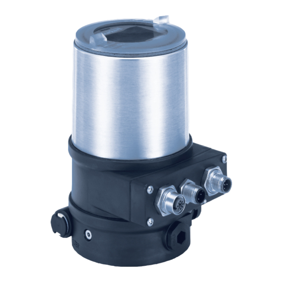
Positioner / process controller
Hide thumbs
Also See for 8692:
- Operating instructions manual (252 pages) ,
- Quick start manual (116 pages) ,
- Supplement to operating instructions (28 pages)
Table of Contents
Advertisement
Quick Links
Advertisement
Table of Contents

Related Manuals for Bürkert 8692


Summary of Contents for Bürkert 8692
- Page 1 Type 8692, 8693 REV.2 Positioner / Process Controller Operating Instructions...
- Page 2 We reserve the right to make technical changes without notice. Technische Änderungen vorbehalten. Sous réserve de modifications techniques. © Bürkert Werke GmbH & Co. KG, 2017 Operating Instructions 1710/01_EU-EN_00810576 / Original DE...
-
Page 3: Table Of Contents
Type 8693, process controller ..................17 STRUCTURE AND FUNCTION ......................18 6.1 Representation ...........................18 6.2 Function diagram ........................19 6.2.1 Diagram illustrating single-acting actuator ..............19 THE POSITION CONTROLLER TYPE 8692 ..................20 7.1 Schematic representation of the position control ..............21 7.2 The position controller software....................22 PROCESS CONTROLLER TYPE 8693 ....................24 8.1 Schematic representation of process control ................25 8.2... - Page 4 11.2.3 Install Type 8692/8693 ....................36 11.3 Installation on process valves, series 26xx and 27xx ............... 38 11.3.1 Install switch spindle ....................38 11.3.2 Install Type 8692/8693 ....................39 11.4 Rotating the actuator module....................41 11.5 Rotating the Types 8692/8693 for process valves belonging to series 26xx and 27xx ..43 11.6 Pneumatic connection of the Type 8692, 8693 ................44 11.7 Model with high air flow rate .....................45 11.7.1 Manual activation of the actuator via pilot valves............45 ELECTRICAL INSTALLATION 24 V DC ....................47...
- Page 5 Type 8692, 8693 REV.2 12.1.4 Slide switch position ....................51 12.1.5 Installing electronics module and housing jacket ............51 12.2 Electrical installation with cable gland ..................52 12.2.1 Terminal assignment: Input signals from the control center (e.g. PLC) ......53 12.2.2 Terminal assignment: Output signals to the control center (e.g. PLC) - (required for analog output and/or digital output option only) ........53...
- Page 6 Type 8692, 8693 REV.2 BASIC SETTING OF THE PROCESS CONTROLLER ................77 15.1 P.CONTROL – Setting up and parameterization of the process controller ......77 15.2 SETUP – Setting up the process controller ................78 15.2.1 PV-INPUT – Specifying signal type for the process actual value ......78 15.2.2 PV-SCALE– Scaling of the process actual value ............78 15.2.3 SP-INPUT –...
- Page 7 19.3 Industrial Ethernet ........................168 19.5 Bus status display ........................170 19.5.1 Differences between the fieldbus devices and devices without a field bus .....170 19.5.2 BUS.COMM – Settings on Type 8692, 8693 ............170 BÜS OPTION ............................171 20.1 Definition ..........................171 20.2 Interfaces ..........................171 20.3 Electrical installation - büS ......................171 20.3.1...
- Page 8 Type 8692, 8693 REV.2 MAINTENANCE AND TROUBLESHOOTING ..................175 21.1 Safety instructions ........................175 21.2 Maintenance ..........................175 21.3 Fault messages ........................175 21.3.1 Error and warning messages while the X.TUNE function is running ......176 21.3.2 Error messages while the P.Q’LIN function is running ..........177 21.3.3 Error messages while the P.TUNE function is running ..........177...
- Page 9 Type 8692, 8693 REV.2 29.2 Adjustment rules according to Chien, Hrones and Reswick (actuating variable jump method) ....................193 TABLES FOR CUSTOMER-SPECIFIC SETTINGS ................195 30.1 Table for your settings on the positioner type 8692 ...............195 30.1.1 Settings of the freely programmable characteristic ..........195 30.2 Table for your settings on the process controller type 8693 ..........196 30.2.1 Set parameters of the process controller ..............196 english...
-
Page 10: Operating Instructions
▶ designates instructions for risk prevention. → designates a procedure which you must carry out. markiert ein Resultat. Definitions of terms The term “device” used in these instructions applies to the compact position controller of type 8692, 8693 REV.2. english... -
Page 11: Authorized Use
The device is designed to be mounted on pneumatic actuators of process valves for the control of media. ▶ In a potentially explosive area, Type 8692 and 8693 may be used only in accordance with the specifica- tion on the separate Ex rating plate. For the use, observe the ATEX manual with safety instructions for the Ex area. -
Page 12: Basic Safety Instructions
▶ When unscrewing and screwing the housing jacket (with transparent cap) in, do not hold the actuator but the electrical connection housing of Type 8692/8693. ▶ Do not supply the pilot air port with aggressive or flammable media or fluids. -
Page 13: General Information
And also on the internet at: www.burkert.com Warranty The warranty is only valid if the Type 8692/8693 are used as intended in accordance with the specified appli- cation conditions. Master code Operation of the device can be locked via a freely selectable user code. In addition, there is a non-changeable master code with which you can perform all operator actions on the device. -
Page 14: Product Description
Product description PRODUCT DESCRIPTION General description Position controller Type 8692 and process controller Type 8693 is a digital electropneumatic position controller for pneumatically actuated control valves with single-acting or double-acting actuators. The device incorpo- rates the main function groups - Position sensor... -
Page 15: Combinations With Valve Types And Mounting Versions
Type 8692, 8693 REV.2 Product description • Housing The housing of Type 8692, 8693 is protected from excessively high internal pressure, e.g. due to leaks, by a pressure limiting valve. Combinations with valve types and mounting versions Position controller Type 8692 and process controller Type 8693 can be mounted on different process valves from the Bürkert range. -
Page 16: Overview Of Mounting Possibilities / Features Of Valve Types
Type 8692, 8693 REV.2 Product description 5.3.1 Overview of mounting possibilities / features of valve types Slanted seat control Diaphragm valves Ball valves Flap valves valves / screw-down stop globe control valves • 2702 • 2730 • 2652 • 2672 Types • 2712 • 2103 • 2655 • 2675 •... -
Page 17: Variants
The position of the actuator is regulated according to the set-point position. The set-point position is specified by an external standard signal (or via field bus). The position controller Type 8692 is operated with a 128 x 64 dot matrix graphics display and a keypad with 4 keys. -
Page 18: Structure And Function
Structure and function STRUCTURE AND FUNCTION The position controller Type 8692 and the process controller Type 8693 consist of the micro-processor con- trolled electronics, the position sensor and the actuating system. The device is designed using three-wire technology. The device is operated by 4 keys and a 128 x 64 dot matrix graphics display. -
Page 19: Function Diagram
Type 8692, 8693 REV.2 Structure and function Function diagram 6.2.1 Diagram illustrating single-acting actuator The black lines in “Figure 3: Function diagram” specify the function of the position controller circuit in Type 8692. The grey part of the diagram indicates the additional function of the superimposed process control circuit in Type 8693. -
Page 20: The Position Controller Type 8692
0. Z1 represents a disturbance variable. Valve opening Position set- Positioner Control system Continuous point value Solenoid valves valve Positioner sensor Position control circuit Figure 4: Position control circuit in Type 8692 english... -
Page 21: Schematic Representation Of The Position Control
Type 8692, 8693 REV.2 The position controller Type 8692 Schematic representation of the position control Figure 5: Schematic representation of position control english... -
Page 22: The Position Controller Software
Type 8692, 8693 REV.2 The position controller Type 8692 The position controller software Configurable auxiliary function Effect Correction line to adjust the operating Selection of the transfer characteristic between input characteristic signal and stroke (correction characteristic). CHARACT Sealing function Valve closes tight outside the control range. Speci-... - Page 23 Type 8692, 8693 REV.2 The position controller Type 8692 Configurable auxiliary function Effect Setting display Adjustment of the display of the process level. EXTRAS SERVICE For internal use only. Simulation software For simulation of the device functions. SIMULATION DIAGNOSE (option) Monitoring of processes.
-
Page 24: Process Controller Type 8693
In the case of process controller Type 8693 the position control mentioned in chapter “7 The position controller Type 8692” becomes the subordinate auxiliary control circuit; this results in a cascade control. The process controller in the main control circuit of Type 8693 has a PID function. -
Page 25: Schematic Representation Of Process Control
Type 8692, 8693 REV.2 Process controller Type 8693 Schematic representation of process control Figure 7: Schematic representation of process control english... -
Page 26: The Position Controller Software
Type 8692, 8693 REV.2 Process controller Type 8693 8.2 The position controller software Configurable auxiliary function Effect Correction line to adjust the operating characteristic Selection of the transfer characteristic between input signal and stroke (correction characteristic). CHARACT Sealing function Valve closes tight outside the control range. Specification... - Page 27 Type 8692, 8693 REV.2 Process controller Type 8693 Configurable auxiliary function Effect Setting display Adjustment of the display of the process level. EXTRAS SERVICE For internal use only. Simulation software For simulation of the device functions. SIMULATION DIAGNOSE (option) Monitoring of processes.
-
Page 28: Interfaces
Type 8692, 8693 REV.2 Interfaces INTERFACES Inputs for position or 2 digital outputs process set-point value 4...20 mA 24 V PNP Position controller / 0...20 mA process controller 0...10 V 0...5 V Input for process actual value * 4...20 mA... -
Page 29: Technical Data
Technical data TECHNICAL DATA 10.1 Conformity Type 8692, 8693 complies with the EU directives according to the EU Declaration of Conformity (if applicable). 10.2 Standards The applied standards, which are used to demonstrate conformity with the EU Directives, are listed in the EU type examination certificate and/or the EU Declaration of Conformity (if applicable). -
Page 30: Type Label
Type 8692, 8693 REV.2 Technical data 10.5 Type label Description of the type label: Example: Type; features of the type key applicable to UL and ATEX Control function; pilot valve 8692 -E3-...-0 PU02 Pilot valve supply voltage Single act Pilot 3.0 24V Pmax 7 bar Maximum operating pressure Tamb -10 - +55°C REV.2... -
Page 31: Electrical Data
Type 8692, 8693 REV.2 Technical data Pressure range control medium 3...7 bar Air flow rate pilot valve / min (for aeration and deaeration) - value according to definition for pressure drop from 7 to 6 bar absolute) optional: 130 l / min (for aeration and deaeration) (only single-acting... -
Page 32: Safety End Positions After Failure Of The Electrical Or Pneumatic Auxiliary Power
Type 8692, 8693 REV.2 Technical data Digital input 0...5 V = log “0”, 10...30 V = log “1” inverted input reversed accordingly (input current < 6 mA) Communications interface Connection to PC with USB büS interface set Communications software Bürkert-Communicator 10.9 Safety end positions after failure of the electrical or... -
Page 33: Installation
1. Attaching the switch spindle Not required for actuators with attached control or for actuators on see page 34 which a control has already been attached. 2. Installing the form seal see page 35 1. Installing Type 8692, 8693 see page 36 english... -
Page 34: Install Switch Spindle
Type 8692, 8693 REV.2 Installation 11.2.1 Install switch spindle DANGER Risk of injury from high pressure in the system/device. ▶ Before loosening the lines and valves, turn off the pressure and vent the lines. Transparent cap Pilot air ports (plug-in hose con- nectors with collets or threaded bushings) -
Page 35: Install Form Seal
Type 8692, 8693 REV.2 Installation NOTE Improper installation may damage the lip seal in the guide element. The lip seal is already be pre-assembled in the guide element and must be “locked into position” in the undercut. ▶ When installing the switch spindle, do not damage the lip seal. → Push the switch spindle through the guide element. NOTE Screw locking paint may contaminate the lip seal. ▶ Do not apply any screw locking paint to the switch spindle. -
Page 36: Install Type 8692/8693
Installation of Type 8692/8693 on process valves, example showing Type 2301 During the installation, the collets of the pilot air ports must not be fitted to the actuator. → Aligning actuator with type 8692/8693: 1. Align the pilot air ports of the actuator with the connection pieces of Type 8692/8693 (see “Figure 15”). Fastening screws max. 1,5 Nm (1.1 Ibf ft) - Page 37 NOTE Damage to the PCB or malfunction. ▶ Ensure that the puck lies flat on the guide rail. → Push Type 8692/8693 without turning it onto the actuator until no gap is visible on the form seal. NOTE To comply with the degree of protection IP65 / IP67, do not fasten the fastening screws too tightly. ▶ Maximum tightening torque: 1.5 Nm.
-
Page 38: Installation On Process Valves, Series 26Xx And 27Xx
Installation on process valves, series 26xx and 27xx Procedure: 1. Attaching the switch spindle Not required for actuators with attached control or for actuators on which a control has already been attached. 2. Installing Type 8692, 8693 11.3.1 Install switch spindle Guide element Spindle extension... -
Page 39: Install Type 8692/8693
Push the puck holder onto the switch spindle until it engages. 11.3.2 Install Type 8692/8693 → Place Type 8692/8693 onto the actuator. In doing so, align the puck of the actuator with the guide rail of Type 8692/8693 (see “Figure 19”). Guide rail Puck... - Page 40 1,5 Nm Actuator Upper pilot air port Lower pilot air port Figure 20: Installation of Type 8692/8693 on process valves belonging to series 26xx and 27xx Establish the pneumatic connection between Type 8692/8693 and the actuator: → Screw the plug-in hose connectors onto the Type 8692/8693 and the actuator. →...
-
Page 41: Rotating The Actuator Module
Type 8692, 8693 with attached actuator is designated as the actuator module. Following installation of the process valve, if the display of Type 8692, 8693 is only partially visible or the connection cables or hoses are difficult to fit, the actuator module can be rotated into a suitable position. - Page 42 Type 8692, 8693 REV.2 Installation Actuator module Key contour Hexagon Nipple Nipple Process valves belonging to series 27xx Process valve Types 2300 and 2301 Figure 21: Rotating the actuator module → Using a suitable open-end wrench, counter the wrench flat on the pipe.
-
Page 43: Rotating The Types 8692/8693 For Process Valves Belonging To Series 26Xx And 27Xx
Rotate the Type 8692/8693 into the required position. NOTE To comply with the degree of protection IP65 / IP67, do not fasten the fastening screws too tightly. ▶ Maximum tightening torque: 1.5 Nm. → Tighten the fastening screws hand-tight only (maximum tightening torque: 1.5 Nm). → Re-attach the pneumatic connections between the Type 8692/8693 and the actuator. If required, use longer hoses. english... -
Page 44: Pneumatic Connection Of The Type 8692, 8693
Type 8692, 8693 REV.2 Installation 11.6 Pneumatic connection of the Type 8692, 8693 DANGER Risk of injury from high pressure in the system/device. ▶ Before working on the system or device, switch off the pressure and vent/drain lines. Observe the following for the proper functioning of the device: ▶ The installation must not cause back pressure to build up. -
Page 45: Model With High Air Flow Rate
Type 8692, 8693 REV.2 Installation 11.7 Model with high air flow rate In the version with high air rate, the actuator can be moved to its end position without electrical power. The actuator moves from its rest position to the end position. To do this, the pilot valves must be activated with a screwdriver. - Page 46 Type 8692, 8693 REV.2 Installation Move the actuator back to the rest position Turn the hand lever to the left with a screwdriver. Please note: - Do not press the lever while turning it - Follow the order described below →...
-
Page 47: Electrical Installation 24 V Dc
Type 8692, 8693 REV.2 Electrical installation 24 V DC ELECTRICAL INSTALLATION 24 V DC There are 2 connection variants for Type 8692, 8693: • Multi-pole with circular plug-in connector • Cable gland with connection terminals Signal values Operating voltage: 24 V DC Set-point value (process/position controller): 0...20 mA;... -
Page 48: X1 - M12 Circular Connector, 8-Pole
Procedure: → Connect Type 8692, 8693 according to the tables. When the operating voltage is applied, Type 8692, 8693 is operating. → Now make the required basic settings and adjustments for the position controller/process controller. The procedure is described in chapter “14 Start-up”, page 72. -
Page 49: X6 - M12 Circular Connector, 4-Pole, Operating Voltage
Type 8692, 8693 REV.2 Electrical installation 24 V DC Pin Wire color* Assignment Output signals to the control center (e.g. PLC) – (required for analog output and/or digital output option only) brown Digital outputs GND green Digital output 2 (24 V / 0 V) yellow Digital output 1 (24 V / 0 V) Analog position feedback gray Analog position feedback + (0/4...20 mA or 0...5 / 10 V) -
Page 50: X5 - M8 Circular Connector, 4-Pole, Input Signals Process Actual Value 4 (For Type 8693 Only)
Type 8692, 8693 REV.2 Electrical installation 24 V DC 12.1.3 X5 - M8 circular connector, 4-pole, input signals process actual value (for Type 8693 only) Input On the Pin Assignment Switch *** External circuit type* device side 4...20 mA +24 V transmitter power - internally... -
Page 51: Slide Switch Position
Slide switch position The description EtherNet/IP, PROFINET and Modbus TCP can be found in chapter “19”. The description option büS can be found in chapter “20”. When the operating voltage is applied, Type 8692, 8693 is operating. → Now make the required basic settings and adjustments for the position controller and process controller. The procedure is described in chapter “14 Start-up”. -
Page 52: Electrical Installation With Cable Gland
Type 8692, 8693 REV.2 Electrical installation 24 V DC NOTE Malfunction due to ingress of dirt and moisture. To comply with the degree of protection IP65 / IP67, ensure that the housing jacket and the electrical connection housing are screwed together tightly. → Switch on operating voltage on the device. -
Page 53: Terminal Assignment: Input Signals From The Control Center (E.g. Plc)
Type 8692, 8693 REV.2 Electrical installation 24 V DC Switch 1 2 3 Connection cover Connection terminals Figure 30: Cable gland connection 12.2.1 Terminal assignment: Input signals from the control center (e.g. PLC) Terminal Assignment External circuit / signal level 0...5 V (log. 0) Digital input + 10...30 V (log. -
Page 54: Terminal Assignment: Process Actual Value Input (For Type 8693 Only)
Type 8692, 8693 REV.2 Electrical installation 24 V DC 12.2.3 Terminal assignment: Process actual value input (for Type 8693 only) Input On the Terminal Assignment Switch ** External circuit type* device side 4...20 mA GND (identical to GND - internally operating voltage) supplied Bridge after GND (GND from... -
Page 55: Terminal Assignment: Operating Voltage
Operating voltage +24V Table 16: Terminal assignment; operating voltage When the operating voltage is applied, Type 8692, 8693 is operating. → Now make the required basic settings and adjustments for the position controller/process controller. For a description see chapter “14 Start-up”. -
Page 56: Operation
▶ Observe the safety instructions and intended use. ▶ Only adequately trained personnel may operate the equipment/the device. There are different operating levels for the operation and setting of type 8692, 8693. • Process level: The running process is displayed and operated on the process level. -
Page 57: Description Of The Operating And Display Elements
Type 8692, 8693 REV.2 Operation 13.1 Description of the operating and display elements The device features 4 keys for operation and a 128 x 64 dot matrix graphics display as a display element. The display is adjusted to the set functions and operating levels. - Page 58 Type 8692, 8693 REV.2 Operation Display elements of the setting level: Menu designation M A I N INPUT BUS.COMM Submenu X.TUNE ADD.FUNCTION EXIT ENTER Designation for the function of the keys Figure 32: Display elements of the setting level Display elements of the process level: Symbol for position control Symbol for process control Symbol for the AUTOMATIC operating state Other symbols are displayed according to the activated functions.
-
Page 59: Description Of The Symbols Which Are Displayed On The Process Level
Type 8692, 8693 REV.2 Operation 13.1.1 Description of the symbols which are displayed on the process level The symbols which are displayed depend on • Type, • Operation as position or process controller, • AUTOMATIC or MANUAL operating state and •... -
Page 60: Led For Indicating Device Status
Type 8692, 8693 REV.2 Operation 13.2 LED for indicating device status Status LED for indicating device status Figure 34: Status LED for indicating device status The status LED lights up according to NAMUR NE 107, in the color specified for the device status. -
Page 61: Function Of The Keys
Type 8692, 8693 REV.2 Operation 13.3 Function of the keys The function of the 4 keys for operation differs depending on the operating state (AUTOMATIC or MANUAL) and operating level (process level or setting level). The description of the operating levels and operating states can be found in chapter and “13 Operation” and“13.7 Operating states”. Key function on the process level: Key function Description of the function... -
Page 62: Entering And Changing Numerical Values
Type 8692, 8693 REV.2 Operation 13.3.1 Entering and changing numerical values Changing numerical values with fixed decimal places: Description of the function Example function Change to the next decimal place (from right to <- Arrow key left). After reaching the last decimal place, the display switches back to the first decimal place. -
Page 63: Adjusting The Display
Type 8692, 8693 REV.2 Operation 13.4 Adjusting the display The display can be individually adjusted for the operation and monitoring of the process. • To do this, menu options can be activated for displaying the process level. POS and CMD are activated in the as-delivered state. - Page 64 Type 8692, 8693 REV.2 Operation Graphical display of POS and CMD with time axis CMD / POS (t) MENU HOLD Time, weekday and date CLOCK 12:00 Thu. 01 . 0 9 . 1 1 MENU INPUT INPUT X.TUNE Input signal for set-point position INPUT (0...5/10 V or 0/4...20 mA)
-
Page 65: Switching Between The Operating Levels
Type 8692, 8693 REV.2 Operation 13.5 Switching between the operating levels Switch to the setting level as follows: → Select MENU and press for 3 seconds. You are on the setting level. Switch to the process level as follows: → Select EXIT. You are on the process level. - Page 66 Type 8692, 8693 REV.2 Operation Activate EXTRAS and CLOCK as follows: → Press MENU for 3 s. Switching from process level setting level. → Select ADD.FUNCTION. → Select ENTER. The possible auxiliary functions are displayed. → Select EXTRAS. → Select ENTER. Activate the EXTRAS auxiliary function by marking with a cross and transfer into the main menu (MAIN).
-
Page 67: Setting Date And Time
Type 8692, 8693 REV.2 Operation 13.6.1 Setting date and time Activate the input screen as follows: → On the process level select the display for CLOCK using the arrow keys. → Press INPUT to open the input screen for the setting. → Set date and time as described in the following table. -
Page 68: Operating States
Type 8692, 8693 REV.2 Operation 13.7 Operating states Type 8692, 8693 has 2 operating states: AUTOMATIC and MANUAL. When the operating voltage is switched on, the device is in the AUTOMATIC operating state. AUTOMATIC In the AUTOMATIC operating state normal controlled operation is implemented. -
Page 69: Activating And Deactivating Auxiliary Functions
Type 8692, 8693 REV.2 Operation 13.8 Activating and deactivating auxiliary functions Auxiliary functions can be activated for demanding control tasks. The auxiliary functions are activated via the ADD.FUNCTION basic function and transferred to the main menu (MAIN). The auxiliary function can then be selected and set in the extended main menu (MAIN). -
Page 70: Deactivating Auxiliary Functions
Type 8692, 8693 REV.2 Operation 13.8.2 Deactivating auxiliary functions Deactivate the auxiliary functions as follows: → Press MENU for 3 s. Switching from process level setting level. → Select ADD.FUNCTION. → Select ENTER. The possible auxiliary functions are displayed. → Select auxiliary function. → Select ENTER. Remove function mark (no cross →... - Page 71 Type 8692, 8693 REV.2 Operation → Select . Deaerating the actuator Control function A (SFA): Valve closes Control function B (SFB): Valve opens Control function I (SFI): Connection 2.2 aerated You have manually opened and closed the valve. SFA: Actuator spring force closing...
-
Page 72: Start-Up
Before start-up, carry out pneumatic, fluid and electrical installation of Type 8692, 8693 and of the valve. For a description see chapters “11” and“12”. When the operating voltage is applied, Type 8692, 8693 is operating and is in the AUTOMATIC operating state. The display shows the process level with the values for POS and CMD. The following basic settings must be made for starting up the device:... -
Page 73: Basic Setting Of The Device
Type 8692, 8693 REV.2 Start-up 14.1 Basic setting of the device The following settings must be made for the basic setting of Type 8692, 8693: Selection of the input signal (see chapter “14.2”). INPUT Automatic self-parameterization of the position controller (see chapter “14.3”). - Page 74 The following functions are actuated automatically: • Adjustment of the sensor signal to the (physical) stroke of the actuator used. • Determination of parameters of the PWM signals to control the solenoid valves integrated in type 8692, 8693. • Adjustment of the controller parameters for the position controller. Optimization occurs according to the criteria of the shortest possible transient time without overshoots.
-
Page 75: X.tune.config - Manual Configuration Of X.tune
Type 8692, 8693 REV.2 Start-up Display Causes of fault Corrective action X.TUNE Control system aeration side leaking. Not possible, device defective. ERROR 4 X.TUNE The end positions for POS-MIN and Check compressed air supply. ERROR 6 POS-MAX are too close together. X.TUNE Incorrect assignment POS-MIN and... - Page 76 Type 8692, 8693 REV.2 Start-up Following activation of P.CONTROL, the P.Q‘LIN and P.TUNE menus are also available in the main menu (MAIN). They offer support for the setting of the process control. P.Q‘LIN L inearization of the process characteristic Description see chapter “15.4” P.TUNE S elf-optimization of the process controller (process tune) Description see chapter “15.5” ADD.FUNCTION – Add auxiliary functions Apart from activating the process controller, ADD.FUNCTION can be used to activate auxiliary functions and incorporate them into the main menu.
-
Page 77: Basic Setting Of The Process Controller
Type 8692, 8693 REV.2 Basic setting of the process controller BASIC SETTING OF THE PROCESS CONTROLLER 15.1 P.CONTROL – Setting up and parameterization of the process controller Set up the process controller as follows: → Press MENU for 3 s. Switching from process level setting level. → Select P.CONTROL. Selection in the main menu (MAIN). -
Page 78: Setup - Setting Up The Process Controller
Type 8692, 8693 REV.2 Basic setting of the process controller 15.2 SETUP – Setting up the process controller These functions specify the type of control. The procedure is described in the following chapters “15.2.1” to “15.2.5”. 15.2.1 PV-INPUT – Specifying signal type for the process actual value One of the following signal types can be selected for the process actual value: •... - Page 79 Type 8692, 8693 REV.2 Basic setting of the process controller 15.2.2.1. Effects and dependencies of the settings of PV-INPUT on PV-SCALE The settings in the PV-SCALE menu have different effects, depending on the signal type selected in PV-INPUT. Even the selection options for the units of the process actual value (in PVmin) depend on the signal type selected in PV-INPUT.
- Page 80 Type 8692, 8693 REV.2 Basic setting of the process controller Example of a sensor calibration for signal type 4...20 mA: Scaling value Scaling: Process actual value [l/min] Process actual value from the trans- PVmax mitter: SPmax 4...20 mA corresponds to 0...10 l/min...
- Page 81 Type 8692, 8693 REV.2 Basic setting of the process controller → Select OK . Return to PV-SCALE. You have set the PVmin. PVmax is set as follows: → Select PVmax. → Select INPUT. The input screen is opened. The last digit of the scaling value has a dark background.
-
Page 82: Sp-Input - Type Of The Set-Point Value Default (Internal Or External)
Type 8692, 8693 REV.2 Basic setting of the process controller → Select EXIT. Return to K-factor. → Select EXIT. Return to PV-SCALE. → Select EXIT. Return to SETUP. You have set the K factor. If the submenu is left by pressing the left selection key , the value remains unchanged. 15.2.3 SP-INPUT – Type of the set-point value default (internal or external) The SP-INPUT menu specifies how the default of the process set-point value is to be implemented. -
Page 83: P.co-Init - Smooth Switchover Manual-Automatic
Type 8692, 8693 REV.2 Basic setting of the process controller Scaling the process set-point value: → Select SP-SCALE → Select ENTER. The submenu options for scaling of the process set-point value are displayed. → Select SPmin. → Select INPUT. The input screen is opened. -
Page 84: Pid.parameter - Parameterizing The Process Controller
15.3.1 DBND – Insensitivity range (dead band) This function causes the process controller to respond from a specific control difference only. This protects both the solenoid valves in Type 8692, 8693 and the pneumatic actuator. Factory setting: 1.0 % with reference to the range of the scaled process actual value (setting in the menu PV-SCALE →... -
Page 85: Kp - Amplification Factor Of The Process Controller
Type 8692, 8693 REV.2 Basic setting of the process controller Insensitivity range for process control Xd2‘ Process set- point value Control (SP) difference to the controller Xd2‘ Process Dead band actual value (PV) Figure 38: Diagram DBND; insensitivity range for process control 15.3.2... -
Page 86: Tn - Reset Time Of The Process Controller
Type 8692, 8693 REV.2 Basic setting of the process controller 15.3.3 TN – Reset time of the process controller The reset time specifies the I-component of the PID controller, can be set with the P.TUNE function. Factory setting: 999.9 s Enter the parameters as follows: →... -
Page 87: Tv - Hold-Back Time Of The Process Controller
Type 8692, 8693 REV.2 Basic setting of the process controller 15.3.4 TV – Hold-back time of the process controller The hold-back time specifies the D-contribution of the PID controller (can be set with the aid of the P.TUNE function). Factory setting: 0.0 s Enter the parameters as follows: →... -
Page 88: X0 - Operating Point Of The Process Controller
Type 8692, 8693 REV.2 Basic setting of the process controller 15.3.5 X0 – Operating point of the process controller The operating point corresponds to the operating point of the proportional portion when control difference = Factory setting: 0.0 % Enter the parameters as follows: →... -
Page 89: P.q'lin - Linearization Of The Process Characteristic
Type 8692, 8693 REV.2 Basic setting of the process controller If the submenu is left by pressing the left selection key , the value remains unchanged. Setting the filter effect in 10 stages Corresponds to cut-off frequency Setting (Hz) (Lowest filter effect) 0.07 0.05 (Largest filter effect) 0.03 Table 27: Setting the filter effect On page 195 you will find a table for entering your set parameters. 15.4 P.Q’LIN – Linearization of the process characteristic This function automatically linearizes the process characteristic. -
Page 90: P.tune - Self-Optimization Of The Process Controller
Type 8692, 8693 REV.2 Basic setting of the process controller Display of the node which is currently running (progress is indicated by a progress bar along the upper edge of the display). Q.LIN ready Automatic linearization was successfully completed. →... -
Page 91: The Operating Mode Of
Type 8692, 8693 REV.2 Basic setting of the process controller 15.5.1 The operating mode of P.TUNE The P.TUNE function automatically identifies the process. To do this, the process is activated with a defined disturbance variable. Typical process characteristics are derived from the response signal and the structure and parameters of the process controller are determined on the basis of the process characteristics. -
Page 92: Starting The Function
Type 8692, 8693 REV.2 Basic setting of the process controller Enter the process set-point value as follows: ( Setting on the process level) → Select SP. The process set-point value is indicated on the display. → Select INPUT. The input screen for inputting the process set-point value is displayed. → Input value <- Select decimal point Increase value The selected set-point value SP should be near the future operating point. - Page 93 Type 8692, 8693 REV.2 Basic setting of the process controller You have set the P.TUNE function. To stop P.TUNE, press the left or right selection key STOP The changed data is saved in the memory (EEPROM) only when there is a switch to the process level, by leaving the main menu (MAIN) using the left selection key EXIT Possible fault messages when running P.TUNE: Display Cause of fault Corrective action TUNE Manual termination of self-optimization err/break by pressing the EXIT key.
-
Page 94: Auxiliary Functions
Type 8692, 8693 REV.2 Auxiliary functions AUXILIARY FUNCTIONS The device has auxiliary functions for demanding control tasks. This chapter describes how the auxiliary functions are activated, set and configured. Overview and description of the auxiliary functions: ADD.FUNCTION Description CHARACT Selection of the transfer characteristic between input signal and stroke... -
Page 95: Including Auxiliary Functions In The Main Menu
Type 8692, 8693 REV.2 Auxiliary functions 16.1.1 Including auxiliary functions in the main menu Add auxiliary functions to ADD.FUNCTION as follows: → Press MENU for 3 s. Switching from process level setting level. → Select ADD.FUNCTION. → Select ENTER. The possible auxiliary functions are displayed. → Select required auxiliary function →... -
Page 96: Charact - Selection Of The Transfer Characteristic Between Input Signal (Set-Point Position) And Stroke
Type 8692, 8693 REV.2 Auxiliary functions 16.1.3 CHARACT – Selection of the transfer characteristic between input signal (set-point position) and stroke Characteristic (customer-specific characteristic) Use this auxiliary function to select a transfer characteristic with reference to set-point value (set-point position, CMD) and valve stroke (POS) for correction of the flow line or operating characteristic. - Page 97 For this reason it is occasionally necessary to correct the course of the operating characteristic in a suitable way. For this purpose Type 8692, 8693 features a transfer element which implements different characteristics. These are used to correct the operating characteristic.
- Page 98 Type 8692, 8693 REV.2 Auxiliary functions → Enter value: Input value for the selected node. Increase value - Reduce value → Select OK . Acknowledge input and return to the FREE submenu. → Select EXIT. Return to the CHARACT menu.
-
Page 99: Cutoff - Sealing Function
Type 8692, 8693 REV.2 Auxiliary functions 16.1.4 CUTOFF – Sealing function This function causes the valve to be sealed outside the control range. To do this, the limits for the set-point position (CMD) are entered as a percentage from which the actuator is fully deaerated or aerated. -
Page 100: Dir.cmd - Effective Direction Of The Position Controller Set-Point Value
Type 8692, 8693 REV.2 Auxiliary functions The changed data is saved in the memory (EEPROM) only when there is a switch to the process level, by leaving the main menu (MAIN) using the left selection key EXIT Valve stroke [%] Adjustable from 75...100 % (POS) Set-point value [%] (CMD) Adjustable from 0...25 % Figure 42: CUTOFF graph; 16.1.5 DIR.CMD – Effective direction of the position controller set-point value You can use this auxiliary function to set the effective direction between the input signal(INPUT) and the set- point position (CMD) of the actuator. -
Page 101: Dir.act - Effective Direction Of The Actuating Drive
Type 8692, 8693 REV.2 Auxiliary functions Set-point position (CMD) Input signal (INPUT) Figure 43: DIR.CMD graph 16.1.6 DIR.ACT – Effective direction of the actuating drive Use this auxiliary function to set the effective direction between the aeration state of the actuator and the actual position (POS). -
Page 102: Spltrng - Signal Split Range
P.CONTROL = not activated. Use this auxiliary function to limit the position set-point position range of Type 8692, 8693 by specifying a minimum and a maximum value. As a result, it is possible to split a used standard signal range (4...20 mA, 0...20 mA, 0...10 V or 0...5 V) over several devices (without or with overlapping). -
Page 103: X.limit - Limit Of The Mechanical Stroke Range
Type 8692, 8693 REV.2 Auxiliary functions Valve stroke [%] (POS) Set-point value [mA] (INP) Set-point value range Set-point value range Position controller 1 Position controller 2 Figure 45: SPLTRNG graph 16.1.8 X.LIMIT – Limit of the mechanical stroke range This auxiliary function limits the (physical) stroke to specified percentage values (minimum and maximum). In doing so, the stroke range of the limited stroke is set equal to 100 %. -
Page 104: X.time - Limiting The Control Speed
Type 8692, 8693 REV.2 Auxiliary functions The changed data is saved in the memory (EEPROM) only when there is a switch to the process level, by leaving the main menu (MAIN) using the left selection key EXIT Limited stroke (%) Physical stroke (%) (POS) (POS) Unlimited stroke Limited stroke Set-point value [mA] (INPUT) Figure 46: X.LIMIT graph 16.1.9 X.TIME – Limiting the control speed Use this auxiliary function to specify the opening and closing times for the total stroke and to limit the control speeds. -
Page 105: 16.1.10 X.control - Parameterization Of The Position Controller
Type 8692, 8693 REV.2 Auxiliary functions → Enter value: Closing time for total stroke (in seconds) Adjustment range: 1...60 seconds Increase value - Reduce value → Select OK *. Acknowledge input and return to the display of X.TIME. You have entered the limit of the control speed. -
Page 106: 16.1.11 P.control - Setting Up And Parameterization Of The Process Controller
(see auxiliary function “16.1.8 X.LIMIT – Limit of the mechanical stroke range”). This function causes the controller to respond only from a specific control difference; as a result the solenoid valves in Type 8692, 8693 and the pneumatic actuator are protected. Xd1‘ Control... -
Page 107: Security - Code Protection For The Settings
Type 8692, 8693 REV.2 Auxiliary functions 16.1.12 SECURITY – Code protection for the settings Use the SECURITY function to prevent Type 8692, 8693 or individual functions from being accessed unintentionally. Factory setting: Access Code: 0000 If the code protection is activated, the code (set Access Code or master code) must be input whenever operator action is disabled. -
Page 108: Safepos - Inputting The Safety Position
Type 8692, 8693 REV.2 Auxiliary functions 16.1.13 SAFEPOS – Inputting the safety position This function specifies the actuator safety position which is started at defined signals. The set safety position is only started • if a corresponding signal is applied to the digital input (configuration see chapter “16.1.15 BINARY.IN – Activation of the digital input”) or •... - Page 109 Type 8692, 8693 REV.2 Auxiliary functions The signal type is set in the following menus: 1. INPUT (for Types 8692 and 8693): See chapter “14.2 INPUT - Setting the input signal”. 2. P.CONTROL (for Type 8693 only and when process controller activated): See chapter “15.2.1 PV-INPUT – Specifying signal type for the process actual value”. NOTE: The fault detection is only possible if the external set-point value default was selected in SP-INPUT. See chapter “15.2.3 SP-INPUT – Type of the set-point value default (internal or external)”. Set the signal fault detection for input signal as follows: ( Setting on the process level) → Select SIG.ERROR. (To do this, the auxiliary function must be incorporated into the main menu). →...
-
Page 110: Binary.in - Activation Of The Digital Input
Type 8692, 8693 REV.2 Auxiliary functions → Select SELEC. The selection is marked by a filled circle → Select EXIT and return to the SP/CMD Input menu. → Select EXIT and return to the SIG.ERROR menu. You have set the signal fault detection for input signal. - Page 111 Type 8692, 8693 REV.2 Auxiliary functions → Select different BIN.IN. Select SafePos. Approaching SafePos, select Manu/Auto. Switch over operating state, select X.Tune. Start X.TUNE, select X.CO / P.CO. Switching between position controller and process controller or select BIN.IN type and activate normally open or normally closed →...
-
Page 112: Output - Configuration Of The Outputs (Option)
16.1.16.1. OUT ANALOG - Configuration of the analog output Type 8692: The feedback of the current position (POS) or of the set-point value (CMD) can be transmitted to the control center via the analog output. Type 8693: The feedback of the current position (POS) or of the set-point value (CMD), of the process actual value (PV) or of the process set-point value (SP) can be transmitted to the control center via the analog output. - Page 113 Type 8692, 8693 REV.2 Auxiliary functions → Select PV. Output of the process actual value. (For Type 8693 only, process control) → Select SELEC. The selection is marked by a filled circle → Select SP. (For Type 8693 only (process control) → Select SELEC. Output of the process set-point value.
- Page 114 Type 8692, 8693 REV.2 Auxiliary functions Menu option Switching Description signal ERR.SP/CMD No sensor break available. ERR.PV Sensor break available. Appliance is the AUTOMATIC operating state. Remote Appliance is the MANUAL operating state. The X.TUNE function is currently not running. The X.TUNE function is currently running.
- Page 115 Type 8692, 8693 REV.2 Auxiliary functions 16.1.16.3. Setting of the submenu options of OUT BIN 1 and OUT BIN 2 Open the submenus as follows: → Press MENU for 3 s. Switching from process level setting level. → Select OUTPUT (to do this, the auxiliary function must be incorporated into the main menu).
- Page 116 Type 8692, 8693 REV.2 Auxiliary functions • ERR.PV - Outputting the message: Sensor break for process actual value (for Type 8693 only) Only available if the function in the SIG.ERR menu has been activated (SIG.ERR → PV Input → Error on). See chapter “16.1.14 SIG.ERROR – Configuration of signal level fault detection”. • Remote - Output AUTOMATIC / MANUAL operating state •...
-
Page 117: Cal.user - Calibration Of Actual Value And Set-Point Value
Type 8692, 8693 REV.2 Auxiliary functions → Select EXIT. Switching from setting level process level. You have input OUT.type. Switching statuses Switching signal normally open normally closed 24 V 24 V Table 32: OUT BIN 1/2; switching statuses The changed data is saved in the memory (EEPROM) only when there is a switch to the process level, by leaving the main menu (MAIN) using the left selection key EXIT 16.1.17 CAL.USER – Calibration of actual value and set-point value The following values can be manually calibrated with this function: •... - Page 118 Type 8692, 8693 REV.2 Auxiliary functions 16.1.17.1. Calibration of the position actual value and the set-point position Calibrate CAL.USER as follows: → Press MENU for 3 s. Switching from process level setting level. → Select CAL.USER. (To do this, the auxiliary function must be incorporated into the main menu).
- Page 119 Type 8692, 8693 REV.2 Auxiliary functions 16.1.17.2. Calibration of the process set-point value and the process actual value Calibrate CAL.USER as follows: → Press MENU for 3 s. Switching from process level setting level. → Select CAL.USER. (To do this, the auxiliary function must be incorporated into the main menu).
- Page 120 Type 8692, 8693 REV.2 Auxiliary functions → Select OK. Transfer and simultaneous return to the CAL.USER menu. → Select EXIT. Acknowledgment and simultaneous return to the main menu (MAIN). → Select EXIT. Switching from setting level process level. You have calibrated CAL.USER.
-
Page 121: Set.factory - Reset To Factory Settings
Type 8692, 8693 REV.2 Auxiliary functions 16.1.18 SET.FACTORY – Reset to factory settings This function allows all settings implemented by the user to be reset to the delivery status. All EEPROM parameters with the exception of the calibration values are reset to default values. Then a hardware reset is implemented. -
Page 122: Extras - Setting The Display
Type 8692, 8693 REV.2 Auxiliary functions 16.2.1 EXTRAS – Setting the display This function can be used to individually set the display. • In DISP.ITEMS the display of the process level can be individually set. To do this, further menu options can be activated for the display of the process level. POS and CMD are activated in the as-delivered state. - Page 123 Type 8692, 8693 REV.2 Auxiliary functions The activated menu options are now displayed on the process level display. Use the arrow keys to switch between the displays. Each menu option which can be selected can also be deactivated so that it is not indicated on the process level display. However, there must be at least one menu option available which can be indicated on the display. If nothing was selected, the POS menu option is automatically activated. START-UP.ITEM - Specifying menu option for the start display: → START-UP.ITEM EXTRAS Select menu option and specify with SELEC.
-
Page 124: Service
DISP.MODE menus are set in the same way. 16.2.2 SERVICE This function is of no importance to the operator of Type 8692, 8693. It is for internal use only. 16.2.3 SIMULATION – Menu for simulation of set-point value, process... - Page 125 Type 8692, 8693 REV.2 Auxiliary functions The following parameters can be set for the selected waveform. Menu Parameter setting Schematic representation with sine wave option 70 % Offset (Zero offset as %) 50 % Offset as % 70 % Amplitude (Amplitude as %) Amplitude as %...
- Page 126 Type 8692, 8693 REV.2 Auxiliary functions → Increase value <- Select decimal point and enter value. → Select OK. Transfer and simultaneous return to the SIGNAL.sim menu. → Select amplitude (amplitude as %). → Select INPUT. The input screen for specifying the amplitude is opened.
- Page 127 Type 8692, 8693 REV.2 Auxiliary functions 16.2.3.2. CONTROL.sim – Simulation of the process and process valve The settings to simulate the process and the process valve are made in the CONTROL.sim menu. Settings Type of simulation: Simulation of the process valve.
-
Page 128: Diagnose - Menu For Monitoring Valves (Option)
Type 8692, 8693 REV.2 Auxiliary functions → Select SELEC. Activate the selection by checking the box or deactivate it by unchecking the Setting the parameters for simulation of the process and/or the process valve: → Select SIM.Gain. (Amplification factor). →... - Page 129 Type 8692, 8693 REV.2 Auxiliary functions 16.2.4.1. Activation of the DIAGNOSE menu To ensure that the DIAGNOSE menu can be set, it must first be activated in the main menu of the setting level (MAIN) via ADD.FUNCTION. See chapter “16.1 Activating and deactivating auxiliary functions”...
- Page 130 Type 8692, 8693 REV.2 Auxiliary functions Activate the diagnostic functions as follows: → Press MENU for 3 s. Switching from process level setting level. → Select DIAGNOSE. (To do this, the DIAGNOSE auxiliary function must already have been acti- vated by incorporation into the main menu (MAIN)).
- Page 131 Type 8692, 8693 REV.2 Auxiliary functions View and delete diagnostic messages as follows: → Select D.MSG. → Select ENTER. All generated diagnostic messages are displayed. → Select required message → Select ENTER. Opening the diagnostic message. The description text is displayed (in English). → Select EXIT.
- Page 132 Type 8692, 8693 REV.2 Auxiliary functions TEMP.CHECK Out of specification STROKE.CHECK Out of specification PV.MONITOR Out of specification POS.MONITOR Out of specification Table 37: CONFIG.MSG; factory setting (Default) Assign the status signals as follows: → Select CONFIG.MSG. → Select ENTER. All activated diagnostic functions, which can output a message, are displayed.
- Page 133 Type 8692, 8693 REV.2 Auxiliary functions In the menu of some diagnostic functions there is a HISTORY submenu in which the history entries are saved. RESET.HISTORY is used to delete the entries of all HISTORY submenus. Individual entries can be deleted in the HISTORY submenu of the particular diagnostic function. See chapter “16.2.4.6. History entries in the HISTORY submenu”. Delete the history entries as follows: → Select RESET.HISTORY. → Hold down RUN as long as countdown (5 ...) is running. All history entries are deleted. → Select EXIT. Return to the DIAGNOSE main menu.
- Page 134 Type 8692, 8693 REV.2 Auxiliary functions 16.2.4.5. Description of the diagnostic functions HISTOGRAM – Output of histograms The HISTOGRAM menu is divided into 2 parts: 1. O utputting the histograms for POS class (dwell time density) and DIR class (movement range) 2. List of the characteristic values for CMD Set-point position valve actuator...
- Page 135 Type 8692, 8693 REV.2 Auxiliary functions Explanation of the histogram in the example Sinusoidal progression of the actuator position: Position 100 % Time [t] Figure 52: Sinusoidal progression of the actuator position Histogram of the sinusoidal progression of the actuator position: Duration of histogram recording Largest dwell time density which occurred (tallest bar)
- Page 136 Type 8692, 8693 REV.2 Auxiliary functions Explanation of the histogram in the example Sinusoidal progression of the actuator position: Position 100 % Time [t] Figure 55: Sinusoidal progression of the actuator position Histogram of the sinusoidal progression of the actuator position: Duration of histogram recording Percentage of the change in direction class which occurred most...
- Page 137 Type 8692, 8693 REV.2 Auxiliary functions Starting histograms: → Hold down START* as long as countdown (5 ...) is running. Both histograms (POS class and DIR class) are started. → Change display view. Selection options: POS class (Histogram for the dwell time density), DIR class (Histogram for the movement range), SYSTEM DATA (list of the characteristic values).
- Page 138 Type 8692, 8693 REV.2 Auxiliary functions Specify the interval for outputting messages as follows: → Select SERVICE.TIME. (To do this, the SERVICE.TIME function must be incorporated into the DIAGNOSE main menu. See chapter“16.2.4.3. Activation of diagnostic functions”). → Select ENTER. The menu is displayed. → Select LIMIT.
- Page 139 Type 8692, 8693 REV.2 Auxiliary functions Specify the interval for outputting messages as follows: → Select TRAVEL.ACCU. (To do this, the TRAVEL.ACCU function must be incorporated into the DIAGNOSE main menu. See chapter “16.2.4.3. Activation of diagnostic functions”). → Select ENTER. The menu is displayed. * Required for analog position sensor only (setting the HUB submenu) →...
- Page 140 Type 8692, 8693 REV.2 Auxiliary functions Specify the interval for outputting messages as follows: → Select CYCLE.COUNTER. (To do this, the CYCLE.COUNTER function must be incorporated into the DIAGNOSE main menu. See chapter “16.2.4.3. Activation of diagnostic functions”.) → Select ENTER. The menu is displayed. → Select LIMIT.
- Page 141 Type 8692, 8693 REV.2 Auxiliary functions Specify the temperature limit for outputting messages as follows: → Select TEMP.CHECK. (To do this, the TEMP.CHECK function must be incorporated into the DIAGNOSE main menu. See chapter “16.2.4.3. Activation of diagnostic functions”. → Select ENTER. The menu is displayed. → Select LIMIT.
- Page 142 Type 8692, 8693 REV.2 Auxiliary functions Display STROKE.CHECK Description of the functions MAX indicates the maximum position of the slave pointer STROKE.CHECK MIN indicates the minimum position of the slave pointer. 67.6 % 30. 9 % The tolerance band for the physical end positions can be set in the LIMIT LIMIT submenu.
- Page 143 Type 8692, 8693 REV.2 Auxiliary functions → Select EXIT. Return to the DIAGNOSE main menu. You have specified the position limit for outputting messages. POS.MONITOR –Position monitor The POS.MONITOR function monitors the current position of the actuator. The tolerance band for the set-point value is specified in the DEADBAND submenu.
- Page 144 Type 8692, 8693 REV.2 Auxiliary functions Set the tolerance band and the compensation time as follows: → Select POS.MONITOR. (To do this, the POS.MONITOR function must be incorporated into the DIAGNOSE main menu. See chapter “16.2.4.3. Activation of diagnostic functions”). → Select ENTER. The menu is displayed. DEADBAND has already been selected.
- Page 145 Type 8692, 8693 REV.2 Auxiliary functions 16.2.4.6. History entries in the HISTORY submenu Each diagnostic function, which can output a message, has the HISTORY submenu. When the diagnostic message is actuated, a history entry is created with date and value. The history entries of the respective diagnostic function can be viewed and deleted in the HISTORY submenu.
-
Page 146: Manual Configuration Of X.tune
Type 8692, 8693 REV.2 Auxiliary functions 16.3 Manual configuration of X.TUNE This function is required for special requirements only. For standard applications the X.TUNE function has been preset at the factory. See chapter “14.3 X.TUNE – Automatic adjustment of the position controller”. For special requirements the X.TUNE function, as described below, can be manually configured. Open the menu for the manual configuration of X.TUNE as follows: → Press MENU for 3 s. Switching from process level setting level. - Page 147 Type 8692, 8693 REV.2 Auxiliary functions → Select required functions in succession using the arrow keys activate by checking the box → Select EXIT. Return to the Manual.TUNE menu. You have specified the functions in X.TUNE.CONFIG. 16.3.1.2. X.TUNE.POS – Setting of the end positions In this menu you can specify whether the pneumatic actuator has mechanical end positions or not.
- Page 148 Type 8692, 8693 REV.2 Auxiliary functions 16.3.1.3. M.TUNE.PWM – Optimization of the PWM signals In this menu the PWM signals for control of the aeration valves and bleed valves are manually optimized. For optimization the actuator is aerated and bled. A progress bar on the display indicates the position of the actuator and the speed of aeration and deaeration.
- Page 149 Type 8692, 8693 REV.2 Auxiliary functions 16.3.1.4. M.TUNE.AIR – Determination of the opening and closing times By running this function, the opening and closing times of the valve are determined continuously. A change to the supply pressure will affect the aeration time which can be optimized in this way.
-
Page 150: Access To The Büs Service Interface
Type 8692, 8693 REV.2 Access to the büS service interface ACCESS TO THE BÜS SERVICE INTERFACE The büS service interface is located inside the device. → It can be accessed by removing the hood (transparent cover and housing jacket). →... - Page 151 Type 8692, 8693 REV.2 Access to the büS service interface Position controller Parameter Diagnostics Maintenance DIAGNOSE ON/OFF BUS.COMM X.TUNE CONFIG.MSG ADD.FUNCTION ADD.DIAGNOSE CHARACT HISTOGRAM CUTOFF SERVICE.TIME DIR.CMD TRAVEL.ACCU DIR.ACT CYCLE.COUNTER SPLTRNG TEMP.CHECK X.LIMIT STROKE.CHECK X.TIME PV.MONITOR X.CONTROL POS.MONITOR SAFEPOS Table 45:...
-
Page 152: Operating Structure And Factory Setting
Type 8692, 8693 REV.2 Operating structure and factory setting OPERATING STRUCTURE AND FACTORY SETTING The factory presets are highlighted in blue to the right of the menu in the operating structure. Examples: Menu options activated or selected at the factory Menu options not activated or selected at the factory sec, ... - Page 153 Type 8692, 8693 REV.2 Operating structure and factory setting Automatic X.TUNE X.TUNE X.TUNE STARTED TUNE #0 INIT ... X.TUNE ready Manual X.TUNE X.TUNE.CONFIG X.TUNE.DBDx X.TUNE.PARAx X.TUNE.LEAKAGE X.TUNE.Ypwm X.TUNE.Yfric X.TUNE.POS ACT.limit ACT.nolimit POS.pMIN POS.pMAX X.TUNE.PWM yB.min TUNE.yB yE.min TUNE.yE time.open X.TUNE.AIR P.Q‘LIN...
- Page 154 Type 8692, 8693 REV.2 Operating structure and factory setting P.Q‘LIN Q.LIN#0 Q.LIN#1 Q.LIN CMD=0% CMD=10% ... ready P.TUNE starting identifying calculating TUNE process tune control process PID parameters ready ADD.FUNCTION CHARACT CUTOFF DIR.CMD DIR.ACT SPLTRNG X.LIMIT X.TIME X.CONTROL P.CONTROL SECURITY SAFEPOS SIG.ERROR...
- Page 155 Type 8692, 8693 REV.2 Operating structure and factory setting Activatable auxiliary functions CHARACT linear GP 1:25 GP 1:33 GP 1:50 GP 25:1 GP 33:1 GP 50:1 Graph FREE GRAPH y 0 –> y 5 –> • • • y 100 –> 100 %...
- Page 156 Type 8692, 8693 REV.2 Operating structure and factory setting Activatable auxiliary functions 1.0 % X.CONTROL DBND 1.0 % KXopn KXcls KDopn KDcls YBfric YEfric 1.0 % P.CONTROL PID.PARAMETER DBND 1.0 % 1.00 1.00 999.9 sec 999.9 0.0 sec FILTER SETUP PV-INPUT 4-20 mA...
- Page 157 Type 8692, 8693 REV.2 Operating structure and factory setting Activatable auxiliary functions SP-INPUT internal external 0.0 l/s SP-SCALE SPmin 100.0 l/s SPmax 100.0 P.CO-INIT bumpless standard zeroinit 0000 SECURITY Access Code CODE MAIN MANU/AUTO ADDFUNCT X.TUNE P.Q‘LIN P.TUNE SAFEPOS Figure 64: Operating structure - 6 Only process controller Type 8693 Only for signal type frequency (P.CONTROL →...
- Page 158 Type 8692, 8693 REV.2 Operating structure and factory setting Activatable auxiliary functions SAFEPOS Safepos SIG.ERROR SP/CMD Input Error off Error on SAFEPOS SafePos off SafePos on PV Input Error off Error on SAFEPOS SafePos off SafePos on BINARY.IN SafePos Manu/Auto X.TUNE X.CO/P.CO BIN.IN type...
- Page 159 Type 8692, 8693 REV.2 Operating structure and factory setting 1.0 % OUT BIN 1 POS.Dev Deviation 1.0 % POS.Lim-1 Limit 0.0 % Safepos ERR.SP/CMD ERR.PV Remote Tune.Status DIAG.State-1 FAILURE OUT SPEZ FUNC.CHECK MAINTENANCE OUT.type normally open normally closed 1.0 % OUT BIN 2 POS.Dev...
- Page 160 Type 8692, 8693 REV.2 Operating structure and factory setting Activatable auxiliary functions CAL.USER calibr. POS POS.pMIN * Value is set for X.TUNE (automatic or manual). POS.pMAX calibr. INP INP 4mA ** Value is set by the manufacturer during device-specific calibration. INP 20mA 0 calibr.
- Page 161 Type 8692, 8693 REV.2 Operating structure and factory setting EXTRAS DISP.ITEMS CMD/POS CMD/POS (t) SP/PV SP/PV (t) CLOCK INPUT TEMP X.TUNE P.TUNE P.LIN SERVICE START-UP.ITEMS Figure 68: Operating structure - 10 1) Only process controller Type 8693 16) Not for field bus...
- Page 162 Type 8692, 8693 REV.2 Operating structure and factory setting Activatable auxiliary functions START-UP.ITEMS CMD/POS CMD/POS (t) SP/PV SP/PV (t) CLOCK INPUT TEMP X.TUNE P.TUNE P.LIN DISP.MODE normal inverse DISP.LIGHT user active SERVICE SIMULATION Figure 69: Operating structure - 11 1) Only process controller Type 8693...
- Page 163 Type 8692, 8693 REV.2 Operating structure and factory setting Activatable auxiliary functions SIMULATION SIGNAL.sim SIGNAL.form External Sine wave Square Triangle Mixed 50.0 % Offset 80.0 % Amplitude 5.0 sec Period CONTROL.sim x.SIM p.SIM SIM.Gain 1.0 sec SIM.Delay DIAGNOSE D.MSG SERVICE.TIME TRAVEL.ACCU CYCLE.COUNTER TEMP.CHECK...
- Page 164 Type 8692, 8693 REV.2 Operating structure and factory setting TRAVEL.ACCU FAILURE FUNC.CHECK OUT.SPEZ MAINTENANCE CYCLE.COUNTER FAILURE FUNC.CHECK OUT.SPEZ MAINTENANCE TEMP.CHECK FAILURE FUNC.CHECK OUT.SPEZ MAINTENANCE STROKE.CHECK FAILURE FUNC.CHECK OUT.SPEZ MAINTENANCE PV.MONITOR FAILURE FUNC.CHECK OUT.SPEZ MAINTENANCE POS.MONITOR FAILURE FUNC.CHECK OUT.SPEZ MAINTENANCE ADD.DIAGNOSE...
- Page 165 Type 8692, 8693 REV.2 Operating structure and factory setting ADD.DIAGNOSE HISTOGRAM SERVICE.TIME TRAVEL.ACCU CYCLE.COUNTER TEMP.CHECK STROKE.CHECK PV.MONITOR POS.MONITOR RESET.HISTORY Reset done Activatable diagnostic functions HISTOGRAM POS class DIR class SYSTEM DATA 90d. 00h SERVICE.TIME LIMIT NEXT M. HISTORY 20.0 mm TRAVEL.ACCU 1000000 cm LIMIT NEXT.M...
- Page 166 Type 8692, 8693 REV.2 Operating structure and factory setting Activatable diagnostic functions TEMP.CHECK CURRENT 60.0 °C LIMIT TEMP.MAX 0.0 °C TEMP.MIN HISTORY TEMP.MAX TEMP.MIN STROKE.CHECK 0.5 % LIMIT LIMIT ZERO.TOL 0.5 % MAX.TOL HISTORY ZERO 2.0 % POS.MONITOR DEADBAND 10.0 sec COMP.TIME HISTORY 2.0 %...
-
Page 167: Ethernet/Ip, Profinet And Modbus Tcp
Type 8692, 8693 REV.2 EtherNet/IP, PROFINET and Modbus TCP ETHERNET/IP, PROFINET AND MODBUS TCP 19.1 View X6 - M12 circular connector, 4-pole X7 - fieldbus connection M12 (operating voltage) (2 port Ethernet switch) Figure 74: Field bus connection 19.2 Technical data DANGER Risk of injury due to electric shock. ▶ Before reaching into the system, switch off the power supply and secure to prevent reactivation. -
Page 168: Industrial Ethernet
Type 8692, 8693 REV.2 EtherNet/IP, PROFINET and Modbus TCP 19.3 Industrial Ethernet PROFINET IO specifications Topology recognition LLDP, SNMP V1, MIB2, physical device Minimum cycle time 10 ms not supported MRP (Media Redundancy) MRP Client is supported Additional supported DCP, VLAN priority tagging, Shared Device... - Page 169 Type 8692, 8693 REV.2 EtherNet/IP, PROFINET and Modbus TCP 19.4 Electrical connection The EtherNet/IP is connected with an M12 circular plug-in connector, 4-pole D-coded. X7 - M12 field bus connection D-coded: Pin 1 Transmit + Pin 2 Receive + Pin 3 Transmit – Pin 4 Receive –...
-
Page 170: Bus Status Display
Chapter “16.1.15 BINARY.IN – Activation of the digital input” Chapter “16.1.16 OUTPUT – Configuration of the outputs (option)” 19.5.2 BUS.COMM – Settings on Type 8692, 8693 Set the following menu options in the BUS.COMM menu for start-up of the Ethernet version: Activate or deactivate approach of the safety position... -
Page 171: 20 Büs Option
Type 8692, 8693 REV.2 büS option büS OPTION 20.1 Definition büS is a field bus which is based on CANopen with additional functionality for networking several devices. 20.2 Interfaces Supply büS Position controller 8692 Input for process büS actual value* 4...20mA... -
Page 172: Electrical Connection
Type 8692, 8693 REV.2 büS option 20.3.2 Electrical connection X3 - circular plug-in connector M12x1, 5-pole, male: Wire color Assignment CAN shield CAN shield Not used Black Black GND / CAN_GND White White CAN_H Blue Blue CAN_L Table 52: Connection of the circular plug-in connector... -
Page 173: Accepting And Saving Sim Card Data (Option)
Type 8692, 8693 REV.2 büS option 20.4 Accepting and saving SIM card data (option) The optionally available SIM card can be used to save and transfer device-specific values and user settings to a different device. A SIM card which has just been inserted is checked by the device for existing data. If applicable, this data is accepted or overwritten: •... -
Page 174: Bus.comm - Settings On Type 8692, 8693
Type 8692, 8693 REV.2 büS option 20.4.1 BUS.COMM – Settings on Type 8692, 8693 Set the following menu options in the BUS.COMM menu for start-up of the Ethernet version: Activate or deactivate approach of the safety position BUS FAIL Selection SafePos off – The actuator remains in the position which corresponds to the set-point value last transferred (default setting). -
Page 175: Maintenance And Troubleshooting
Type 8692, 8693 REV.2 Maintenance and troubleshooting MAINTENANCE AND TROUBLESHOOTING 21.1 Safety instructions WARNING Risk of injury from improper maintenance work. ▶ Maintenance may be carried out only by trained technicians and with the appropriate tools. ▶ Secure system against unintentional activation. ▶ Following maintenance, ensure a controlled restart. -
Page 176: Error And Warning Messages While The X.tune Function Is Running
Type 8692, 8693 REV.2 Maintenance and troubleshooting 21.3.1 Error and warning messages while the X.TUNE function is running Display Causes of error Remedial action TUNE Manual termination of self-parame- err/break terization by pressing the EXIT key. X.TUNE locked The X.TUNE function is blocked Input access code X.TUNE... -
Page 177: Error Messages While The P.q'lin Function Is Running
Type 8692, 8693 REV.2 Maintenance and troubleshooting 21.3.2 Error messages while the P.Q’LIN function is running Display Cause of fault Remedial action TUNE Manual termination of linearization by err/break pressing the EXIT key. P.Q LIN No supply pressure connected. Connect supply pressure. ERROR 1 No change to process variable. - Page 178 Type 8692, 8693 REV.2 Maintenance and troubleshooting For Ethernet/IP, PROFINET, Modbus TCP Display Device state Explanation Troubleshooting (is displayed approx. every 3 seconds) • New connection established by BUS no Online, Device is connected correctly to the connection bus, the network access procedure master. No connection has ended without faults, however to the master.
-
Page 179: Malfunctions
Type 8692, 8693 REV.2 Maintenance and troubleshooting 21.4 Malfunctions Problem Possible causes Corrective action POS = 0 (when CMD > 0 %) or Sealing function (CUTOFF) is Deactivate sealing POS = 100 %, (when CMD < 100 %). unintentionally activated. function. PV = 0 (when SP > 0) or PV = PV (when SP >... -
Page 180: Accessories
Type 8692, 8693 REV.2 Accessories ACCESSORIES Accessories Order number Connection cable with M12 socket, 8-pole, (length 5 m) 919267 Connection cable with M12 socket, 4-pole, (length 5 m) 918038 Connection cable with M8 socket, 4-pole, (length 5 m) 92903474 Connection cable with M12 circular connector, 4-pole, (length 5 m) -
Page 181: Removal Of Type 8692, 8693
Type 8692, 8693 with process valve of Type 2103, 2300 or 2301 of series 26xx or 27xx Figure 78: Removing the pneumatic connections → Disconnect the pneumatic connections to Type 8692, 8693. For process valves belonging to series 26xx and 27xx: → Disconnect the pneumatic connections to the actuator. english... -
Page 182: Disconnecting Electrical Connections
Removing Type 8692, 8693 Types 8692, 8693 Fastening screws Fastening screws Type 8692, 8693 with process valve Type 8692, 8693 with process valve of series 26xx or 27xx of Type 2103, 2300 or 2301 Figure 80: Disconnecting electrical connections →... -
Page 183: Packaging And Transport
Type 8692, 8693 REV.2 Packaging and transport PACKAGING AND TRANSPORT NOTE Transport damages Inadequately protected equipment may be damaged during transport. • During transportation protect the device against wet and dirt in shock-resistant packaging. • Avoid exceeding or dropping below the allowable storage temperature. STORAGE NOTE Incorrect storage may damage the device. • Store the device in a dry and dust-free location. -
Page 184: Selection Criteria For Continuous Valves
Type 8692, 8693 REV.2 Selection criteria for continuous valves SELECTION CRITERIA FOR CONTINUOUS VALVES The following criteria are crucial for optimum control behavior and to ensure that the required maximum flow is reached: • the correct selection of the flow coefficient which is defined primarily by the orifice of the valve;... - Page 185 Type 8692, 8693 REV.2 Selection criteria for continuous valves The k value of the continuous valve should have at least the value which is calculated according to equation (1) or (2) which is appropriate to the application, however it should never be far above the calculated value. The rule of thumb "slightly higher is never harmful" often used for switching valves may greatly impair the control behavior of continuous valves! value of the continuous valve can be specified in practice via the so-called valve authority Ψ: The upper limit for the k ∆ ² ψ...
-
Page 186: Properties Of Pid Controllers
Type 8692, 8693 REV.2 Properties of PID Controllers PROPERTIES OF PID CONTROLLERS A PID controller has a proportional, an integral and a differential portion (P, I and D portion). 28.1 P-portion Function: Kp is the proportional coefficient (proportional gain). It is the ratio of the adjusting range ∆Y to the proportional range ∆Xd. -
Page 187: I-Portion
Type 8692, 8693 REV.2 Properties of PID Controllers 28.2 I-portion Function: ∫ Ti is the integral action time or actuating time. It is the time which passes until the actuating variable has run through the whole adjustment range. Characteristic and step response of the I portion of a PID controller Ymax... -
Page 188: D-Portion
Type 8692, 8693 REV.2 Properties of PID Controllers 28.3 D-portion Function: ⋅ Kd is the derivative action coefficient. The larger Kd is, the greater the D-effect is. Characteristic and step response of the D portion of a PID controller Step response Ramp response Figure 83: Characteristic and step response of the D portion of a PID controller... -
Page 189: Superposition Of P, I And D Portions
Type 8692, 8693 REV.2 Properties of PID Controllers 28.4 Superposition of P, I and D Portions Function: ∫ ⋅ Where Kp · Ti = Tn and Kd/Kp = Tv the function of the PID controller is calculated according to the fol- lowing equation: ∫... -
Page 190: Implemented Pid Controller
Type 8692, 8693 REV.2 Properties of PID Controllers 28.5 Implemented PID controller 28.5.1 D Portion with delay In the process controller Type 8693 the D portion is implemented with a delay T. Function: ⋅ ⋅ Superposition of P, I and DT Portions Figure 85: Characteristic of superposition of P, I and DT Portions 28.5.2... -
Page 191: Adjustment Rules For Pid Controllers
Type 8692, 8693 REV.2 Adjustment rules for PID Controllers ADJUSTMENT RULES FOR PID CONTROLLERS The control system Type 8693 features a self-optimization function for the structure and parameters of the integrated process controller. The determined PID parameters can be seen via the operating menu and re- optimized at will for an empirical path. - Page 192 Type 8692, 8693 REV.2 Adjustment rules for PID Controllers The controller parameters can then be calculated from K and T according to the following table. krit krit Adjustment of the parameters according to Ziegler and Nichols Controller type Adjustment of the parameters P controller Kp = 0.5 K...
- Page 193 Type 8692, 8693 REV.2 Adjustment rules for PID Controllers 29.2 Adjustment rules according to Chien, Hrones and Reswick (actuating variable jump method) With this method the controller parameters are adjusted on the basis of the transient behavior of the controlled system.
- Page 194 Type 8692, 8693 REV.2 Adjustment rules for PID Controllers Adjustment of the parameters according to Chien, Hrones and Reswick Adjustment of the parameters Controller type for aperiodic control process for control process (0% overshoot) with 20% overshoot Reference Malfunction Reference Malfunction Kp = P controller Kp = 0,3 ·...
-
Page 195: Tables For Customer-Specific Settings
Type 8692, 8693 REV.2 Tables for customer-specific settings TABLES FOR CUSTOMER-SPECIFIC SETTINGS 30.1 Table for your settings on the positioner type 8692 30.1.1 Settings of the freely programmable characteristic Node Valve stroke [%] (position set-point Date: Date: Date: Date: value as %) -
Page 196: Table For Your Settings On The Process Controller Type 8693
Type 8692, 8693 REV.2 Tables for customer-specific settings 30.2 Table for your settings on the process controller type 8693 30.2.1 Set parameters of the process controller Date: Date: Date: Date: DBND PVmin PVmax SPmin SPmax UNIT K-Factor FILTER english... - Page 197 www.burkert.com...
Need help?
Do you have a question about the 8692 and is the answer not in the manual?
Questions and answers