Burkert Positioner TopControl Basic 8696 Quick Start Manual
Hide thumbs
Also See for Positioner TopControl Basic 8696:
- Quick start manual (64 pages) ,
- Quick start manual (30 pages)

Related Manuals for Burkert Positioner TopControl Basic 8696


Summary of Contents for Burkert Positioner TopControl Basic 8696
- Page 1 Type 8696 Positioner TopControl Basic Electropneumatic Position Controller Elektropneumatischer Stellungsregler Positionneur électropneumatiques Quickstart English Deutsch Français...
- Page 2 We reserve the right to make technical changes without notice. Technische Änderungen vorbehalten. Sous réserve de modifications techniques. © Bürkert Werke GmbH & Co. KG, 2007 - 2017 Quickstart 1805/07_EU-ML_00805654 / Original DE...
-
Page 3: Table Of Contents
Type 8696 Table of Contents INSTALLATION ..............12 QUICKSTART ................ 4 7.1 Safety instructions ............. 12 1.1 Definition of term / abbreviation ........4 7.2 Installation of the positioner on process valves of 1.2 Symbols ............... 4 series 2103 and 23xx ............12 AUTHORIZED USE ............... 5 PNEUMATIC INSTALLATION ..........14 BASIC SAFETY INSTRUCTIONS .......... 5 ELECTRICAL INSTALLATION .......... -
Page 4: Quickstart
Quickstart explains, for example, how to install and start-up the device. CAUTION! A detailed description of the device can be found in the oper- Warns of a possible danger. ating instructions for positioner Type 8696. ▶ Failure to observe this warning may result in a medium or minor injury. The operating instructions can be found on the Internet at: NOTE! www.burkert.com Warns of damage to property. Definition of term / abbreviation indicates important additional information, tips and The term “device” used in these instructions always stands for recommendations. the positioner Type 8696. In these instructions, the abbreviation “Ex” always refers to refers to information in these operating instructions or in “potentially explosive”. -
Page 5: Authorized Use
Type 8696 Authorized use AUTHORIZED USE BASIC SAFETY INSTRUCTIONS These safety instructions do not make allowance for any Non-authorized use of the positioner Type 8696 may be a • contingencies and events which may arise during the installation, hazard to people, nearby equipment and the environment. operation and maintenance of the devices. ▶ The device is designed to be mounted on pneumatic actua- tors of process valves for the control of media. • local safety regulations – the operator is responsible for observing ▶ Do not expose the device to direct sunlight. these regulations, also with reference to the installation personnel. ▶ Use according to the authorized data, operating conditions and conditions of use specified in the contract documents and operating instructions. These are described in the chap- ter entitled... - Page 6 Type 8696 Basic safety instructions To prevent damage to property of the device, ensure: General hazardous situations. ▶ Do not feed any aggressive or flammable media into the pilot To prevent injury, ensure: air port. ▶ In the potentially explosion-risk area the positioner Type 8696 ▶ Do not feed any liquids into the pilot air port. may be used only according to the specification on the separate approval sticker. For use observe the additional instructions ▶ When unscrewing and screwing in the body casing or the enclosed with the device together with safety instructions for transparent cap, do not hold the actuator of the process valve the explosion-risk area. but the connection housing of Type 8696. ▶ Devices without a separate approval sticker may not be used ▶ Do not put any loads on the housing (e.g. by placing objects in a potentially explosive area. on it or standing on it).
-
Page 7: General Information
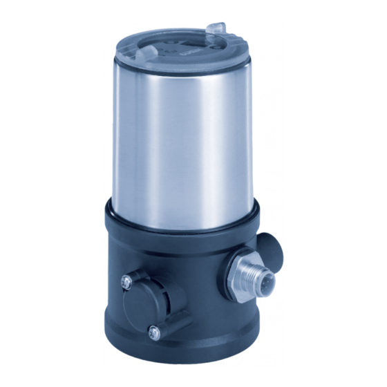
GENERAL INFORMATION SYSTEM DESCRIPTION Contact address Structure and function Germany Bürkert Fluid Control System Sales Center Positioner Chr.-Bürkert-Str. 13-17 D-74653 Ingelfingen Tel. + 49 (0) 7940 - 10 91 111 Fax + 49 (0) 7940 - 10 91 448 E-mail: info@burkert.com Actuator International Contact addresses can be found on the final pages of the printed Process valve operating instructions. And also on the Internet at: Valve body www.burkert.com Warranty Fig. 1: Structure 1... -
Page 8: Model For Control Of Third-Party Devices
Type 8696 System description Model for control of third-party Electrical connection devices (circular plug-in connector) A special model enables the positioner Type 8696 to be attached to third-party devices. Pilot air port (label: 1) This model has a different pneumatic connection housing so that the pilot air ports can be connected to the outside of the actuator. Exhaust air port (label: 3) Electrical connection Connection housing (circular plug-in connector) Exhaust air port Transparent cap removed: Key 1 (label: 3) LED 1 Fastening screws (2 x) DIP Switches LED 2 Key 2... -
Page 9: Technical Data
Type 8696 Technical data TECHNICAL DATA Conformity “In rest position” means that the pilot valves of the posi- tioner Type 8696 are isolated or not actuated. In accordance with the EU Declaration of conformity, the posi- tioner Type 8696 is compliant with the EU Directives. If the ambient air is humid, a hose can be connected Standards between pilot air outlet 2 of the positioner and the uncon- The applied standards, which verify conformity with the EU nected pilot air port of the third-party device for control Directives, can be found on the EU-Type Examination Certificate function A or control function B. As a result, the spring and / or the EU Declaration of Conformity. -
Page 10: Mechanical Data
Type 8696 Technical data Type labels Ambient temperature see type label Degree of protection: 6.6.1 Type label (example) Type; Features of the type code applicable Evaluated by the manufacturer: Evaluated by UL: to UL and ATEX IP65 / IP67 according to EN UL Type 4x Rating Control function; pilot valve; Supply voltage pilot valve 60529 8696 -E1-...-0 PU02 Single act Pilot 0.6 24V Max. operating pressure Pmax 7 bar Tamb -10 - +60 °C Max. ambient temperature S/N 1001 2) Only if cables, plugs and sockets have been connected correctly and Serial number; CE mark... -
Page 11: Pneumatic Data
Type 8696 Technical data Pneumatic data Electrical data Control medium: neutral gases, air WARNING! Quality classes in accordance with ISO 8573-1 Only circuits with limited power may be used for UL approved Dust content Class 7: max. particle size 40 µm, components according to “NEC Class 2”. max. particle density 10 mg/m³ Connections C ircular plug-in connector Water content Class 3: max. pressure dew point (M12 x 1, 8-pole) - 20 °C or min. 10 °C below the lowest operating temperature Pilot valve S upply voltage... -
Page 12: Factory Settings Of The Positioner
▶ Observe applicable accident prevention and safety regulations for electrical equipment. Additional functions are described in the operating WARNING! instructions Type 8696. These instructions can be found on the Internet at Risk of injury from improper installation. www.burkert.com. ▶ Installation may be carried out by authorized technicians only and with the appropriate tools. Risk of injury from unintentional activation of the system and an uncontrolled restart. ▶ Secure system from unintentional activation. ▶ Following assembly, ensure a controlled restart. -
Page 13: Installation Of The Positioner On Process Valves Of Series 2103 And 23Xx
Type 8696 Installation Installation of the positioner on process → Push the positioner, without turning it, onto the actuator until no gap is visible on the form seal. valves of series 2103 and 23xx NOTE! NOTE! When mounting on process valves with a welded body, Too high torque when screwing in the fastening screw does follow the installation instructions in the operating instruc- not ensure protection class IP65 / IP67. -
Page 14: Pneumatic Installation
Type 8696 Pneumatic installation PNEUMATIC INSTALLATION Important information for the problem-free functioning of the device: DANGER! ▶ The installation must not cause back pressure to build Risk of injury from high pressure in the equipment/device. ▶ Select a hose for the connection with an adequate ▶ Before working on equipment or device, switch off the pressure cross-section. and deaerate/drain lines. ▶ The exhaust air line must be designed in such a way that no water or other liquid can get into the device through the exhaust air port. Procedure: →... -
Page 15: Electrical Installation
Type 8696 Electrical installation Electrical installation with circular ELECTRICAL INSTALLATION plug-in connector All electrical inputs and outputs of the device are not galvanically → Connect the positioner according to the table. isolated from the supply voltage. Safety instructions DANGER! Risk of electric shock. ▶ Before working on equipment or device, switch off the power Fig. 9: Circular plug M12 x 1, 8-pole supply and secure to prevent reactivation. ▶ Observe applicable accident prevention and safety regulations for electrical equipment. Input signals of the control center (e.g. PLC) WARNING! Wire Configuration External circuit / signal level... -
Page 16: Start-Up
Type 8696 Start-up START-UP Operating voltage 10.1 Safety instructions Wire Configuration External circuit color WARNING! green 24 V DC ± 10 % max. residual Risk of injury from improper operation. ripple 10 % yellow + 24 V Improper operation may result in injuries as well as damage to the device and the area around it. - Page 17 Type 8696 Start-up NOTE! Key 1 LED 2 Avoid maladjustment of the controller due to an incorrect DIP Switches pilot pressure or applied operating medium pressure. LED 1 ▶ Run X.TUNE whenever the pilot pressure (= pneumatic aux- Key 2 iliary energy) is available during subsequent operation. • Run the X.TUNE function preferably without operating medium pressure to exclude interference caused by flow forces. Fig. 11: Starting X.TUNE To run X.TUNE, the positioner must be in the AUTOMATIC →...
-
Page 18: 10.3 Control And Display Elements
Type 8696 Start-up → Close the device (assembly tool: 674078 → Screw off the transparent cap of the positioner to operate the keys and DIP switches. Key 1 LED 2 7) The assembly tool (674078) is available from your Bürkert sales office. DIP switches LED 1 Key 2 10.3 Control and display elements Communica- A detailed description of the operation and functions of tions interface the positioner and the communication software can be found in the respective operating instructions. - Page 19 Type 8696 Start-up 10.3.1 Operating status 10.3.2 Functions of the keys The configuration of the 2 keys on the board varies depending on AUTOMATIC (AUTO) the operating status (AUTOMATIC / MANUAL). Normal controller mode is implemented and monitored in AUTO- Key 1 MATIC operating state. LED1 flashes green. Key 2 MANUAL (MANU) In MANUAL operating state the valve can be opened and closed manually via the keys. Fig. 14: Keys LED1 flashes red / green alternately. MANUAL operating status (DIP switch 4 set to ON): Function The DIP switch 4 can be used to switch between the two operating states AUTOMATIC Aerate (manually open / close the actuator) and MANUAL.
- Page 20 Type 8696 Start-up 10.3.3 Function of the DIP switches 10.3.4 Display of the LEDs LED 2 Function switches 1 2 3 4 LED 1 Reversal of the effective direction of the set-point value (set-point value 20 – 4 mA corresponds to position 0 – 100 %), descending (DIR.CMD) Normal effective direction of the set-point value (set-point value 4 – 20 mA corresponds to position 0 – 100 %), ascending Sealing function active. The valve completely closes below 2 % and opens above 98 % of the set-point value (CUTOFF) Fig. 15: Display of the LEDs No sealing function Correction characteristic for adjustment of the operating characteristic (linearization of the...
-
Page 21: Safety Positions
Type 8696 Safety positions SAFETY POSITIONS LED 1 (green / red) LED States Display Safety positions after green failure of the auxiliary Actuator Acceleration phase when Power ON Designation power system flashes Operating status AUTO slowly (AUTOMATIC) electrical pneumatic flashing flashing MANUAL operating status alternating single-acting flashes X.TUNE function Control... -
Page 22: Accessories
Designation Order no. NOTE! USB adapter for connection to a PC in 227093 Transport damages. conjunction with an extension cable Inadequately protected equipment may be damaged during Information at transport. Communicator www.burkert. ▶ During transportation protect the device against wet and dirt in shock-resistant packaging. Connection cable M12 x 1, 8-pole 919061 ▶ Avoid exceeding or dropping below the permitted storage Assembly tool 647078 temperature. Tab. 13: Accessories Incorrect storage may damage the device. - Page 24 www.burkert.com...
Need help?
Do you have a question about the Positioner TopControl Basic 8696 and is the answer not in the manual?
Questions and answers