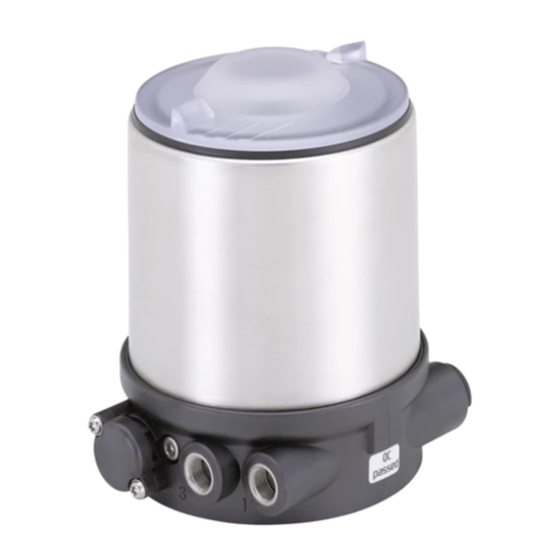
Burkert 8691 Operating Instructions Manual
Control head
Hide thumbs
Also See for 8691:
- Operating instructions manual (190 pages) ,
- Quick start manual (82 pages) ,
- Operating instructions manual (178 pages)
Table of Contents
Advertisement
Advertisement
Table of Contents

Related Manuals for Burkert 8691


Summary of Contents for Burkert 8691
- Page 1 Type 8691 REV.3 Control Head Operating Instructions...
- Page 2 We reserve the right to make technical changes without notice. Technische Änderungen vorbehalten. Sous réserve de modifications techniques. © Bürkert Werke GmbH & Co. KG, 2022 - 2023 Operating Instructions 2303/01_EU-EN_00815428 / Original DE...
-
Page 3: Table Of Contents
Type 8691 REV.3 Control head Type 8691 REV.3 able of conTenTs ABOUT THESE INSTRUCTIONS ......................7 Symbols ............................7 1.2 Definition of terms ........................7 INTENDED USE ............................8 BASIC SAFETY INSTRUCTIONS ......................9 GENERAL INFORMATION ........................10 Contact address .........................10 Warranty .............................10 4.3 Information on the Internet ......................10 Trademarks ..........................10 PRODUCT DESCRIPTION ........................11... - Page 4 Type 8691 REV.3 Inhaltsverzeichnis 6.4.2 Electrical data ......................15 6.4.2.1 Electrical data without fieldbus communication .............15 6.4.2.2 Electrical data, IO-Link ...................16 6.4.2.3 Electrical data, büS....................16 6.4.2.4 Electrical data, AS-Interface ...................17 6.5 Mechanical data .........................17 6.5.1 Safety end positions ....................18 6.6 Communication ..........................18 6.6.1 IO-Link ........................18 MECHANICAL INSTALLATION ......................19 7.1...
- Page 5 Type 8691 REV.3 START-UP .............................37 10.1 Invert process valve direction ....................37 10.2 Teach function: Determine end positions and save these, REV.3 ...........40 10.2.1 Start automatic teach function ...................40 10.2.2 Start manual teach function ..................42 10.2.3 Teach-in-operation function ..................44 10.3 Setting with Bürkert Communicator ..................44 10.3.1 Connecting the device with Bürkert Communicator ..........44 10.4 IO-Link ............................46 10.4.1...
- Page 6 Type 8691 REV.3 DEINSTALLATION ..........................60 13.1 Safety instructions deinstallation ....................60 13.2 Deinstallation ..........................61 SPARE PARTS, ACCESSORIES ......................62 14.1 Communications software ......................62 TRANSPORTATION, STORAGE ......................63 english...
-
Page 7: About These Instructions
Definition of terms In these instructions the term “device” denotes the following device types: Control head Type 8691 REV.3 The term “büS” (Bürkert system bus) used in this instruction stands for the communication bus developed by Bürkert and based on the CANopen protocol. -
Page 8: Intended Use
Type 8691 REV.3 Intended use INTENDED USE The control head Type 8691 REV.3 is designed to be mounted on pneumatic actuators of process valves for the control of media. The permitted fluid media are listed in the technical data. ▶ Use the device for its intended purpose only. Non-intended use of the device may be dangerous to people, nearby equipment and the environment. ▶ Correct transportation, correct storage as well as correct installation, commissioning, operation and maintenance are essential for reliable and problem-free operation. -
Page 9: Basic Safety Instructions
Type 8691 REV.3 Basic safety instructions BASIC SAFETY INSTRUCTIONS These safety instructions do not consider any contingencies or incidents which occur during installation, operation and maintenance. The operator is responsible for observing the location-specific safety regulations, also with reference to the personnel. DANGER Risk of injury from high pressure and discharge of medium. ▶ Before working on the device or system, switch off the pressure. Vent or drain lines. DANGER Risk of injury from electric shock. ▶ Before working on the device or system, switch off the power supply. Secure against reactivation. ▶ Observe applicable accident prevention and safety regulations for electrical equipment. -
Page 10: General Information
Type 8691 REV.3 General information GENERAL INFORMATION Contact address Germany Bürkert Fluid Control System Chr.-Bürkert-Str. 13-17 D-74653 Ingelfingen E-mail: info@burkert.com International Contact addresses can be found on the final pages of the printed operating instructions. Also in the internet at: www.burkert.com Warranty The warranty is only valid if the device is used as intended in accordance with the specified application conditions. -
Page 11: Product Description
Type 8691 REV.3 Product description PRODUCT DESCRIPTION Structure The modular design of the device supports various configurations and variants. View without transparent cap and body casing: Status indicator (RGB LED) Pilot LED (yellow) ASi PWR LED (green)* ASi FAULT LED (red)* büS service interface Manual LED (red) Inv.ValveDir LED (green) -
Page 12: Variants
Type 8691 REV.3 Product description 5.1.3 Variants Communication possible via: • without fieldbus communication: 24 V device with digital inputs and outputs and büS service interface • AS Interface • IO-Link • büS Function This device is capable of controlling single-acting and double-acting process valves. The pilot valves can be manually overridden. An analog, inductive sensor element provides feedback about end positions being reached. The teach function is used for configuration. -
Page 13: Technical Data
Type 8691 REV.3 Technical data TECHNICAL DATA Standards and directives The device complies with the relevant EU harmonisation legislation. In addition, the device also complies with the requirements of the laws of the United Kingdom. The harmonised standards that have been applied for the conformity assessment procedure are listed in the current version of the EU Declaration of Conformity/UK Declaration of Conformity. -
Page 14: Type Label
Type 8691 REV.3 Technical data Type label 6.3.1 Type label standard Operating voltage or fieldbus control Type Control function, pilot valve 8691 büS Max. operating pressure single act pilot 3,0 Pmax 7bar Ambient temperature, version Tamb -10 - +55°C REV.2 Ser.-Nr. 001000 Serial number, CE marking... -
Page 15: Fluidic Data
Type 8691 REV.3 Technical data 6.4.1 Fluidic data Control medium Neutral gases, air Quality classes as per ISO 8573-1 Dust content Class 7 Max. particle size 40 µm, max. particle density 10 mg/m³ Water content class 3 Max. pressure dew point -20°C or min. -
Page 16: Electrical Data, Io-Link
Type 8691 REV.3 Technical data 6.4.2.2 Electrical data, IO-Link Protection class III as per DIN EN 61140 (VDE 0140-1) Connection Supply, IO-Link Circular plug-in connector M12 x 1, 4-pin, port class A Circular plug-in connector M12 x 1, 5-pin, port class B Communication büS service interface Operating voltage System supply (Pin 1+3) -
Page 17: Electrical Data, As-Interface
Type 8691 REV.3 Technical data 6.4.2.4 Electrical data, AS-Interface Protection class III as per DIN EN 61140 (VDE 0140-1) Connection Supply, AS-Interface Circular plug-in connector M12 x 1, 4-pin Communication büS service interface Operating voltage System supply AS-Interface via AS-Interface power supply unit according to specification with (Pin 1+3) 29.5 V...31.6 V only for variant with additional 24 V ±10 %... -
Page 18: Safety End Positions
Type 8691 REV.3 Technical data 6.5.1 Safety end positions Safety end positions after failure of the electrical or pneumatic auxiliary power: Actuator system Designation Safety end positions after failure of the auxiliary power electrical pneumatic single-acting down down control function A... -
Page 19: Mechanical Installation
Type 8691 REV.3 Mechanical installation MECHANICAL INSTALLATION Safety instructions DANGER Risk of injury from high pressure and discharge of medium. ▶ Before working on the device or system, switch off the pressure. Vent or drain lines. WARNING Risk of injury from improper installation. ▶ Only trained technicians may perform installations. ▶ Perform installations with suitable tools only. WARNING Risk of injury due to unintentional activation and uncontrolled start-up of the system. ▶ Secure system against unintentional activation. ▶ Ensure that the system does not start up in an uncontrolled manner. - Page 20 Type 8691 REV.3 Mechanical installation 1. Installing the switch spindle Transparent cap Position indicator Pilot air ports (plug-in connectors with collets or threaded bushings) Actuator Figure 7: Installing the switch spindle (1), integrated pilot air duct → Unscrew the transparent cap from the actuator.
- Page 21 Type 8691 REV.3 Mechanical installation 2. Attaching the form seal → Pull the form seal onto the actuator cover (smaller diameter points upwards). → Check that the O-rings are correctly positioned in the pilot air ports. Before installing the device, remove the collets in the pilot air ports.
-
Page 22: Installing Devices With External Control Air Duct (20Xx, Classic)
Type 8691 REV.3 Mechanical installation Connection piece 2x fastening screw Pilot air ports (max. 1.5 Nm) Figure 11: Installation Installing devices with external control air duct (20xx, Classic) Only for devices without preinstalled process valve. Required attachment kit: Classic Type 20xx for the corresponding variant NOTE Damage to the device and the actuator when welding bodies. - Page 23 Type 8691 REV.3 Mechanical installation Puck Switch spindle Guide element Max. 8 Nm O-ring Max. 1 Nm Actuator cover Plastic part Spindle (actuator) Figure 13: Installing the switch spindle (2), external pilot air duct → Press O-ring down into the actuator cover.
- Page 24 Type 8691 REV.3 Mechanical installation Guide rail Puck Figure 15: Aligning the puck → Press the device all the way down to the actuator and turn it into the required position. Ensure that the pneumatic connections of the device and those of the valve actuator are situated preferably vertically one above the other (see Fig. below). For different positioning, longer hoses may...
- Page 25 Type 8691 REV.3 Mechanical installation Control function A (CFA) Process valve closed in resting position (by spring force) Device Pilot air outlet Actuator Upper pilot air port Lower pilot air port Control function B (CFB) Process valve open in resting position (by spring force)
-
Page 26: Aligning (Turning) The Device And Position Of Connections
Type 8691 REV.3 Mechanical installation Aligning (turning) the device and position of connections Devices with integrated pilot air duct: Alignment of device and position of connections is only possible with 2100, 2101 and 2106 process valves. The device and position of the connections can be aligned by: - turning the actuator Devices with external pilot air duct: The device and position of the connections can be aligned by:... -
Page 27: Turning The Actuator, Devices With Hexnut
Type 8691 REV.3 Mechanical installation 7.4.1 Turning the actuator, devices with hexnut The following description only applies for devices with hexnut on the actuator. For devices without a hexnut on the actuator: refer to the section "Turning the actuator, devices without hexnut" in the operating instructions. The position of the connections can be infinitely adjusted by rotating the actuator through 360°. Actuator Actuator Hexnut Hexnut... -
Page 28: Turning The Actuator, Devices Without Hexnut
Type 8691 REV.3 Mechanical installation 7.4.2 Turning the actuator, devices without hexnut The position of the connections can be infinitely adjusted by rotating the actuator through 360°. Actuator Key-fit forms Wrench flat on the body connection Figure 19: Turning the actuator (1), devices without hexnut → Clamp the valve body into a holding device (only for valves not yet installed). -
Page 29: Turning The Device
Type 8691 REV.3 Mechanical installation 7.4.3 Turning the device Only for devices with external pilot air duct (20xx, Classic). The position of the connections can be aligned by rotating the device continuously through 360°. Device Fastening screw (2x) Pneumatic connection Actuator Figure 21: Turning the device → Loosen pneumatic connection between device and actuator. -
Page 30: Installation On Rotary Actuators Fromthird Party Manufacturers
Type 8691 REV.3 Mechanical installation Installation on rotary actuators fromthird party manufacturers → Align actuator and device to each other (see installation instructions for the adaptation set). → Connect magnetic encoder to actuator shaft and attach using setscrew (maximum tightening torque: 0.5 Nm). -
Page 31: Pneumatic Installation
Type 8691 REV.3 Pneumatic installation PNEUMATIC INSTALLATION Safety instructions DANGER Risk of injury from high pressure and discharge of medium. ▶ Before working on the device or system, switch off the pressure. Vent or drain lines. WARNING Risk of injury from improper installation. ▶ Only trained technicians may perform installations. ▶ Perform installations with suitable tools only. WARNING Risk of injury due to unintentional activation and uncontrolled start-up of the system. ▶ Secure system against unintentional activation. ▶ Ensure that the system does not start up in an uncontrolled manner. -
Page 32: Electrical Installation
Type 8691 REV.3 Electrical installation ELECTRICAL INSTALLATION Safety instructions for electrical installation DANGER Risk of injury from electric shock. ▶ Before working on the device or system, switch off the power supply. Secure against reactivation. ▶ Observe applicable accident prevention and safety regulations for electrical equipment. WARNING Risk of injury from improper installation. ▶ Only trained technicians may perform installations. ▶ Perform installations with suitable tools only. - Page 33 Type 8691 REV.3 Electrical installation → Connect the wires. DO2+ DO1+ +24 V –24 V DI– Figure 25: Connection terminals Assignment DO2+ Digital output end position with actuator activated DO1+ Digital output end position with actuator deactivated +24 V Operating voltage +24 V –24 V...
-
Page 34: Device With Circular Plug-In Connector
Type 8691 REV.3 Electrical installation 9.2.2 Device with circular plug-in connector Figure 26: Pin assignment circular plug (M12 x 1, 8-pin) Wire color* Designation white Digital output (DO2+) end position with actuator activated brown Digital output (DO1+) end position with actuator deactivated... -
Page 35: Connecting The Device Electrically, Io-Link, Port Class B
Type 8691 REV.3 Electrical installation Connecting the device electrically, IO-Link, port class B Figure 28: Pin assignment Designation Assignment IO-Link mode SIO mode 24 V DC 24 V DC Actuator supply L − 0 V (GND) IO-Link DI or DO 0 V (GND) -
Page 36: Connecting The Device Electrically, As-Interface
As an alternative to the bus connection model with 4-pin circular plug, there is the control head with multi- pole cable (M12 circular plug) and flat cable terminal. The wiring diagram of the circular plug corresponds to the bus connection of the M12 4-pin circular plug and can easily be connected to the flat cable terminal (see „Figure 31“). Screws M12 plug-in connector branch circuit Figure 31: Control head 8691 with multi-pole cable and flat cable terminal Handling the flat cable terminal The multi-pole cable features a flat cable terminal - with M12 plug-in connector branch circuit - for AS- Interface flat cable. The flat cable terminal contacts the AS-Interface flat cable by means of penetration technology which allows installation by “clipping in” the AS-Interface flat cable without cutting and without removing insulation. →... -
Page 37: Start-Up
Type 8691 REV.3 Start-up START-UP 10.1 Invert process valve direction In the factory settings, the following actuator end positions and colours of the status indicator are assigned to the valve positions: Valve position Status indicator Actuator position Valve open is lit green... - Page 38 Type 8691 REV.3 Start-up Actuator with rotational movement Rotational movement during aeration: clockwise Rotational movement during aeration: anticlockwise (seen from above) (seen from above) Valve opens when pressurized Valve closes when pressurized → No adjustment required. Valve closes when pressurized Valve opens when pressurized →...
- Page 39 Type 8691 REV.3 Start-up Invert process valve direction: Closing device: Transparent cap Seal (body casing) Body casing Basic housing Actuator Figure 32: Opening or closing the device NOTE Breakage of the pneumatic connection pieces due to rotational impact. ▶ When unscrewing and screwing in the body casing, do not hold the actuator of the process valve but the basic housing.
-
Page 40: Teach Function: Determine End Positions And Save These, Rev.3
Type 8691 REV.3 Start-up 10.2 Teach function: Determine end positions and save these, REV.3 • Automatic teach function: For devices with pilot valve The teach function automatically identifies and saves the end positions of the valve. • Manual teach function: For devices without pilot valve The end positions are captured and saved automatically. - Page 41 Type 8691 REV.3 Start-up Status indicator Pilot LED Manual LED Inv.ValveDir LED Key 1 Key 2 Figure 36: Operating and display elements 10 s Start automatic Status indicator teach function Inv.ValveDir LED End of teach function Manual LED Figure 37: Start automatic teach function →...
-
Page 42: Start Manual Teach Function
Type 8691 REV.3 Start-up Description of workflow for automatic teach function: The status indicator blinks orange when the teach function is running. • The end position is scanned in. • The pilot valve switches. • The actuator moves automatically to the upper position. - Page 43 Type 8691 REV.3 Start-up Status indicator Pilot LED Manual LED Inv.ValveDir LED Key 1 Key 2 Figure 39: Operating and display elements 10 s Start manual Status indicator teach function Inv.ValveDir LED Manual LED End of teach function Figure 40: Start automatic teach function →...
-
Page 44: Teach-In-Operation Function
Type 8691 REV.3 Start-up 10.2.3 Teach-in-operation function The teach-in-operation function can be used if the device is to carry out the end positions of the process valve automatically during normal operation (once when the control unit is switched on for the first time). This function may only be used for process valve actuators with control function A (normally closed). - Page 45 Type 8691 REV.3 Start-up Closing device: Transparent cap Seal (body casing) Body casing Basic housing Actuator Figure 41: Opening or closing the device NOTE Breakage of the pneumatic connection pieces due to rotational impact. ▶ When opening or closing the device, do not press against the actuator, but against the basic housing.
-
Page 46: Io-Link
Type 8691 REV.3 Start-up 10.4 IO-Link 10.4.1 Information, IO-Link IO-Link is an internationally standardized IO technology (IEC 61131-9) to enable sensors and actuators to communicate. IO-Link is a point-to-point communication with 3-wire connection technology for sensors and actuators and unshielded standard sensor cables. -
Page 47: As-Interface
Type 8691 REV.3 Start-up 10.6 AS-Interface AS-Interface (Actuator Sensor Interface) is a field bus system which is used primarily for networking binary sensors and actuators (slaves) with a higher-level control (master). The unshielded two-wire line is used to transmit both the information (data) and the energy to supply the actuators and sensors. 10.6.1 Certification The device is certified according to AS-Interface specification version 3.0. -
Page 48: Operating And Display Elements
Type 8691 REV.3 Operating and display elements OPERATING AND DISPLAY ELEMENTS Status indicator (RGB LED) Pilot LED (yellow) ASi PWR LED (green) ASi FAULT LED (red) büS service interface Manual LED (red) Inv.ValveDir LED (green) Key 1 Key 2 Figure 43:... -
Page 49: Operating State
Type 8691 REV.3 Operating and display elements Description of the displays Status indicator Valve position, error, warning RGB LED see chapter „Status indicator“ Pilot LED yellow Is lit: pilot valve is actuated (on) Manual LED red Is lit: MANUAL operating state active Flashes at 10 Hz for 0–2 s: Switch MANUAL ↔... -
Page 50: Functions Of The Operating And Display Elements
Type 8691 REV.3 Operating and display elements 11.2 Functions of the operating and display elements To operate the buttons, make sure that the local control lock is deactivated/unlocked (factory setting): with communication software or fieldbus communication. Open or close the device: Closing device: Transparent cap Seal (body casing) Body casing Basic housing Actuator Figure 44: Opening or closing the device... - Page 51 Type 8691 REV.3 Operating and display elements Changing the operating state (MANU ↔ AUTO) Oparating state MANU AUTO 10 s Status indicator Manual LED Figure 45: Changing the operating state → Press and hold keys 1 and 2 for > 2 s. The red manual LED flashes for approx. 2 s at 5 Hz. → When the red manual LED starts flashing faster (10 Hz), release keys 1 and 2 within the next 5 s. M ANUAL operating state: the red manual LED is lit and the status indicator flashes orange. AUTO operating state: the red manual LED and the status indicator is not lit.
- Page 52 Type 8691 REV.3 Operating and display elements Perform device restart 10 s 30 s Device restart Inv.ValveDir LED Manual LED Pilot LED Figure 47: Perform device restart → Keep keys 1 and 2 pressed for 10–30 s. The red manual LED flashes for approx. 2 s at 5 Hz, then at 10 Hz. → When the red manual LED flashes more slowly again (5 Hz), release keys 1 and 2 within the next 20 s. The device will restart. Factory reset 10 s 30 s Factory reset Inv.ValveDir LED...
-
Page 53: Status Indicator
Type 8691 REV.3 Operating and display elements 11.3 Status indicator Status indicator (RGB-LED) Figure 49: Status indicator The status indicator (RGB LED) show the device status and the valve position. The user can set the following LED modes: • Valve mode •... -
Page 54: Valve Mode With Error Messages (Valve Mode + Errors)
Type 8691 REV.3 Operating and display elements 11.4.2 Valve mode with error messages (valve mode + errors) Displays in valve mode with error messages (valve mode + errors): • Valve position: open, half-way, closed • Device status: Error Valve position... - Page 55 Type 8691 REV.3 Operating and display elements Valve position Device status: Function check state, color state, color Open is lit yellow* flashes orange alternately with yellow* Half-way LED off* flashes orange alternately with LED off* Closed is lit green* flashes orange alternately with green* Table 21: Valve mode + warnings, device status: Function check...
-
Page 56: Namur Mode
Type 8691 REV.3 Operating and display elements 11.4.4 NAMUR mode The display elements change color in accordance with NAMUR NE 107. If several device statuses exist simultaneously, the device status with the highest priority is displayed. The priority is determined by the severity of the deviation from controlled operation (red LED = failure = highest priority). -
Page 57: Setting The Led Mode, Status Indicator
Type 8691 REV.3 Operating and display elements 11.5 Setting the LED mode, status indicator User level: installer Factory setting: valve mode + warnings Menu or function Values or description Device > General settings > Parameter > Status LED Mode NAMUR mode ... -
Page 58: Switching The Device Manually With Pilot Valve
Type 8691 REV.3 Operating and display elements 11.6 Switching the device manually with pilot valve The device can be switched manually with the pilot valve when the control air is connected. Closing device: Transparent cap Seal (body casing) Body casing... -
Page 59: Maintenance
Type 8691 REV.3 Maintenance MAINTENANCE 12.1 Servicing the air intake filter To protect the pilot valve and actuator, the pilot air is filtered. Air flows through the air intake filter from inside to outside through the filter fabric in its pre-installed state. DANGER! Risk of injury if not maintained correctly. ▶ Only trained and qualified personnel may perform maintenance. ▶ Perform maintenance with suitable tools only. Push-in connector O-ring Air intake filter Figure 53: Servicing the air intake filter DANGER! Risk of injury from high pressure and discharge of medium. ▶ Before working on the device or system, switch off the pressure. Vent or drain lines. →... -
Page 60: Deinstallation
Type 8691 REV.3 Deinstallation DEINSTALLATION 13.1 Safety instructions deinstallation DANGER Risk of injury from high pressure and discharge of medium. ▶ Before working on the device or system, switch off the pressure. Vent or drain lines. DANGER Risk of injury from electric shock. ▶ Before working on the device or system, switch off the power supply. Secure against reactivation. ▶ Observe applicable accident prevention and safety regulations for electrical equipment. WARNING Risk of injury due to improper deinstallation. ▶ Only trained technicians may perform deinstallations. ▶ Perform deinstallations with suitable tools only. -
Page 61: Deinstallation
Type 8691 REV.3 Deinstallation 13.2 Deinstallation Body casing Fastening screws Circular plug-in Basic housing connector Pneumatic connection Pilot air port Actuator External pilot air Exhaust air port duct (Classic) Integrated pilot air duct (Element) Figure 54: Deinstalling the device Pneumatically deinstalling the device →... -
Page 62: Spare Parts, Accessories
Connection cable PUR with socket M12 x 1, 8-pin, length 2 m 919061 Table 25: Accessories 14.1 Communications software The Bürkert Communicator PC program is designed for communication with Type 8691 devices. For questions regarding compatibility, please contact the Bürkert Sales Center. A detailed description for installing and operating the software can be found in the associated operating instructions. Download the software from: www.burkert.com... -
Page 63: Transportation, Storage
Type 8691 REV.3 Transportation, storage TRANSPORTATION, STORAGE NOTE Damage in transit due to inadequately protected devices. ▶ Protect the device against moisture and dirt in shock-resistant packaging during transportation. ▶ Observe permitted storage temperature. NOTE Incorrect storage may damage the device. ▶ Store the device in a dry and dust-free location. ▶ Storage temperature: -20 to +65 °C DISPOSAL ▶... - Page 64 Type 8691 REV.3 english...
- Page 66 www.burkert.com...
Need help?
Do you have a question about the 8691 and is the answer not in the manual?
Questions and answers