
Related Manuals for RGBlink VSP 9516S


Summary of Contents for RGBlink VSP 9516S
-
Page 1: User Manual
VSP 9516S User Manual Manual #: RGB-RD-UM-V9516S E001 Revision: V1.1 VSP 9516S User Manual... - Page 2 Technology Co.,LTD. No part can be copied, reproduced or translated without permission. Notice RGBlink provides this manual ―as is‖ without warranty of any kind, no matter expressed or implied, including but not limited to the implied warranties or merchantability and fitness for a particular purpose. RGBlink may make improvements or changes to the products and the programs described in this publication at any time without notice.
- Page 3 30 days after the transfer of risks. In the event of justified notice of compliant, RGBlink can repair the fault or provide a replacement at its own discretion within an appropriate period. If this measure proves to be impossible or unsuccessful, the purchaser can demand a reduction in the purchase price or cancellation of the contract.
- Page 4 Company Address Xiamen RGBlink Science & Technology Co., Ltd. Headquarter: S603~604 Weiye Building Torch Hi-Tech Industrial Development Zone Xiamen, Fujian Province, P.R.C Shenzhen office: Floor 11, A1 Building, Baiwang R&D Building, Shahe West Road, Xili Town, Nanshan District, Shenzhen, Guangdong Province, P.R.C Beijing office: No.
-
Page 5: Power Source
To avoid fire hazard, use only the fuse having identical type, voltage rating, and current rating characteristics. Refer fuse replacement to qualified service personnel. Do Not Operate in Explosive Atmospheres To avoid explosion, do not operate this product in an explosive atmosphere. VSP 9516S User Manual... - Page 6 Highlights an essential operating procedure, condition or statement. CAUTION The exclamation point within an equilateral triangle is intended to alert the user to the presence of important operating and maintenance (servicing) instructions in the literature accompanying the appliance. VSP 9516S User Manual...
- Page 7 The table below lists the changes to the Video Processor User Manual. Format Time ECO# Description Principal V1.0 2014-02-20 0000# Release Vira V1.1 2014-10-15 0001# 1. Change the back panel. Vira 2. Change the menu tree. VSP 9516S User Manual...
-
Page 8: Table Of Contents
System Overview ................23 Application Questions ................. 24 2. Hardware Orientation ..............25 In This Chapter ................. 25 VSP 9516S Back Panel ..............26 CONT Interface ..................26 2: Dial Switch .................... 26 3: 10/100M UDP Interface ..............27 4: USB Interface ..................27 5: RS232 Interface ................... - Page 9 37: DVI Output ..................29 38: DVI +VGA DVI Output ..............29 Switch and Power ..................29 39.40: Power Interface and Switch ............29 VSP 9516S Front Panel ..............30 OLED Panel ....................31 LED Sending Card Indicator ..............31 Menu Buttons.................... 31 3.
- Page 10 5. Communication Software Guideline ........54 In This Chapter ................. 54 Software Installation ................. 55 Software Operation ................59 Connection ....................59 Use ......................60 File Toolbar ....................60 Communication Toolbar ................63 Device Toolbar ..................63 VSP 9516S User Manual...
- Page 11 How to Connect Windows Control Program by LAN Interface ... 76 How to Connect Windows Control Program by RS232 Interface78 How to Connect Windows Control Program by USB Interface ... 81 6. System Setup and Operations ..........85 In This Chapter ................. 85 VSP 9516S User Manual...
- Page 12 Confirm If There is Any Input Signal ........... 115 Confirm If Signal Output ............... 115 Flash Point in LED Display Output ..........115 Confirm If Monitor Output is Normal ........... 115 LED Display Only Displays Part of the Image ......116 VSP 9516S User Manual...
- Page 13 DP Port Can Only Connect DP Signal ..........118 A. Specification ................119 B. Contact Information ..............122 C. Software Upgrade ..............123 IP Software Download Instruction ..........123 Firmware Upgrade ................. 125 How to Install the SDI Optional Module ........128 VSP 9516S User Manual...
-
Page 14: Brief Introduction
Brief Introduction This chapter is designed to introduce you to the VSP 9516S User Manual. Areas to be covered are: Chapter Structure How to Use the Manual Terms and Definitions System Overview Application Questions VSP 9516S... -
Page 15: Chapter Structure
1. Brief Introduction Chapter Structure Chapter Structure The following chapters provide instructions for all aspects of VSP 9516S operations. Chapter 1 Brief Introduction Chapter 2 Hardware Orientation Chapter 3 Hardware Installation Chapter 4 Menu Orientation Chapter 5 Communication Software Guideline... -
Page 16: How To Use The Manual
For system setup and operations, refer to Chapter 6, ―System Setup and Operations‖ on page 85. Should you have any questions regarding the installation or operation of VSP 9516S, please consult with the factory. Refer to Appendix B ―Contact information‖ on page 122. VSP 9516S... -
Page 17: Term And Definitions
Telecommunications Wiring Standard. “Color bars”: A standard test pattern of several basic colors (white, yellow, cyan, green, magenta, red, blue, and black) as a reference for system alignment and testing. In NTSC video, the most commonly VSP 9516S User Manual... - Page 18 “Frame”: In interlaced video, a frame is one complete picture. A video frame is made up of two fields, or two sets of interlaced lines. In a film, a frame is one still picture of a series that makes up a motion picture. VSP 9516S User Manual...
- Page 19 This alternation helps cancel out phase errors. For this reason, the hue control is not needed on a PAL TV set. PAL, in many transmission forms, is widely used in Western Europe, VSP 9516S User Manual...
- Page 20 This is a 10-bit, scrambled, polarity independent interface with common scrambling for both component ITU-R 601 and composite digital video and four channels of (embedded) digital audio. “Seamless Switching”: A feature found on many video switchers. This VSP 9516S User Manual...
- Page 21 31.5 kHz and vertical frequency of 70 Hz (Mode 1, 2) and 60 Hz (Mode 3). The signal is non-interlaced in modes 1, 2, and 3 and interlaced when using the 8514/A card (35.5 kHz, 86 Hz) in mode 4. It VSP 9516S User Manual...
- Page 22 640×480 with a color palette of 16 bits and 256,000 colors. “YCrCb”: Used to describe the color space for interlaced component video. “YPbPr”: Used to describe the color space for progressive-scan (non-interlaced) component video. VSP 9516S User Manual...
-
Page 23: System Overview
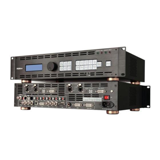
3×CVBS, 1×S-Video, 1×YPbPr, 1×VGA, 1×DVI-I (compatible with HDMI), 1×Displayport, 1×3G-SDI, up to 9 channels inputs, and 2×DVI-I, 1×VGA, up to 3 simultaneous outputs. VSP 9516S is not only a video scaler for video and graphic processing or just provides power and makes room for the sending cards to install inside. -
Page 24: Application Questions
1. Brief Introduction Application Questions Application Questions RGBlink offers solutions to demand technical problems. Any application questions, or required further information, please contact with our Customer Support Engineers. Refer to Appendix B for contact details. VSP 9516S User Manual... -
Page 25: Hardware Orientation
Hardware Orientation In This Chapter This chapter provides detailed information about the VSP 9516S hardware. The following topics are discussed: VSP 9516S Back Panel VSP 9516S Front Panel VSP 9516S User Manual... -
Page 26: Vsp 9516S Back Panel
2. Hardware Orientation VSP 9516S Back Panel VSP 9516S Back Panel The figure below illustrates the professional interface and control signals of VSP 9516S back panel. INTERFACE INTERFACE 3G-SDI Input BNC Port 27~29 CVBS Input BNC port Dial Switch S-Video Input DIN 4... -
Page 27: 3: 10/100M Udp Interface
2. Hardware Orientation VSP 9516S Back Panel and the device will not work. 3: 10/100M UDP Interface Used to connect the windows control program or device upgrade. 4: USB Interface Used to connect the windows control program. 5: RS232 Interface Used to connect the windows control program or device upgrade. -
Page 28: 31: Dvi Input
2. Hardware Orientation VSP 9516S Back Panel compatible). 31: DVI Input DVI input, input the video signal from computer, DVI signal generator. If the EDID is HDMI, the DVI Can be compatible with HDMI 1.3. (This Connection does not support hot-plugging ) Note DVI-I is compatible with HDMI. -
Page 29: 37: Dvi Output
2. Hardware Orientation VSP 9516S Back Panel connected to the DVI output interface video processor directly. (This connector does not support hot-plugging) 37: DVI Output Connect to the monitor or LED display which has DVI interface. (This DVI connector does not support hot-plugging). -
Page 30: Vsp 9516S Front Panel
VSP 9516S Front Panel Insert power cord and push power to ON position. OLED module on the front panel will show RGBLINK and go into self verification before it load last setting and send processed image to the target monitor. For the first setup, CV1 input is default source. -
Page 31: Oled Panel
2. Hardware Orientation VSP 9516S Front Panel VSP 9516S front panel is as following: OLED Panel Used to show button menus and for interactive communication. LED Sending Card Indicator Red: Power indicator, the light is on when device has power supply. - Page 32 2. Hardware Orientation VSP 9516S Front Panel LOAD/PIP2: LOAD and PIP2 function reuse button. Push the knob to enter LOAD mode, turn the knob or push the number button to select LOAD position. Currently, it supports 10 loading modes. The figure: 1, 2, 3, 4, 5, 6, 7, 8, 9, 0 means LOAD SAVE1~10.
- Page 33 2. Hardware Orientation VSP 9516S Front Panel CV1 input selection button, push the button, its LED light is on, output will be switched to this channel. CV2 input selection button, push the button, its LED light is on, output will be switched to this channel.
- Page 34 2. Hardware Orientation VSP 9516S Front Panel disable the black function IMAGE1/IMAGE2: IMAGEA and IMAGE B select reuse button. Freeze button, push the button, its LED light is on, the output image is freeze, push the button again, its LED light is off, and return to live image.
-
Page 35: Hardware Installation
Hardware Installation In This Chapter This chapter provides comprehensive installation instruction for VSP 9516 hardware. Following is the size of VSP 9516S for your reference. VSP 9516S User Manual... -
Page 36: Safety Precautions
Unpacking and Inspection Before opening VSP 9516S process shipping box, inspect it for damage. If you find any damage, notify the shipping carrier immediately for all claims adjustments. As you open the box, compare its contents against the packing slip. -
Page 37: Menu Orientation
Menu Orientation In This Chapter This chapter describes all VSP 9516S processor menus, including how they are accessed, the functions that are available, and descriptions of each menu tree (in block diagram format). The following topics are discussed: • MENU ... -
Page 38: Menu
Push the [MENU/EFFECT] number to enter to the menu items, the menu shown as below. Turn the knob to select the menu item. ―>‖ before the menu means it’s in selected state. Push the knob button to enter corresponding setting or view the menu. VSP 9516S User Manual... - Page 39 4. Menu Orientation MENU VSP 9516S User Manual...
-
Page 40: Input
H POS: Horizontal position setting. V POS: Vertical position setting. RESET: If image quality distorts by improper operation, it can be recover by reset. VGA ADJUST: Adjust VGA input signal, sub menu as follows: H POS: Image horizontal position. VSP 9516S User Manual... -
Page 41: Output
Push the [MENU/EFFECT] button, OLED panel show menu, push the knob to select <OUTPUT>, show menus as follows: OUTPUT DETAIL: Display output signal information of DV1 and DV2, including OUTPUT FORMAT, DVI MODE, BIT DEPTH, DATA RANGE, DE, VSP 9516S User Manual... - Page 42 DVI1, setting as following: DVI MODE: Can set the protocol as HDMI or DVI, default is DVI output, HDMI signal output will enable when HDMI option checked. DATE RANGE: DVI1 output range, can set as RGB (graphic mode or VSP 9516S User Manual...
- Page 43 V SIZE: Height setting. H POS: Horizontal phase setting. V POS: Vertical phase setting. RESET: If image quality distorts by improper operation, it can be recover by reset. NOTE The [SCALE/CROP] button can also fulfill this setting. VSP 9516S User Manual...
- Page 44 COLOR GREEN: It can change the image color green via this setting. COLOR BLUE: It can change the image color blue via this setting. RESET: If image quality distorts by improper operation, it can be recover by reset. VSP 9516S User Manual...
- Page 45 SELECT: Can choose to set the size or position of IMAGE A or IMAGE B individually. Note User can choose image A or image B by [IMAGE 1/IMAGE 2] reuse button. For details, please refer to the instructions in the manual: How to Set up the PIP. VSP 9516S User Manual...
- Page 46 It should combined with "AND/OR" conditions when judging. BELOW: In image 2, if the pixel value is lower than the setting value, then VSP 9516S User Manual...
- Page 47 GAMMA: Gamma setting, press it to adjust the image gamma value; Gamma values include: -1.2, -1.4, -1.6, 1, 1.2, 1.4, 1.6, sRGB. VSP 9516S User Manual...
-
Page 48: Transition
MODE: Switch mode, including the following modes: CUT: Seamless switching. FADE: Fade in fade out. POP L+T: PUSH L+T: POP R+T: PUSH R+T: POP L+B: PUSH L+B: POP R+B: PUSH R+B: POP CENTRE: PUSH CENTRE: POP LEFT: VSP 9516S User Manual... - Page 49 ALPHA: Image transparency setting, the regulating range is among 0 to DEINTERLACE: Force Deinterlace function, can choose ―ON‖ or ―OFF‖. ON: Force interlace for interlaced signal without effect switching, but with effects switching for progressive signal. OFF: No deinterlace, with effect switching. VSP 9516S User Manual...
-
Page 50: Audio
SENDING CARD NO.: User can choose NO.1 card or NO.2 card. BRIGHTNESS: Set the brightness of sending card. QUICK CONNECTION: Including the following settings: SENDING CARD SET: User can set X, Y, and save the settings to sending card. RECEIVING CARD SET: Including the following settings: VSP 9516S User Manual... -
Page 51: Save Setup
SENDING CARD VERSION: Show the sending card version. RECEIVING CARD VERSION: N/A. SAVE SETUP SAVE TO: VSP 9516S provides ten save modes, users can save the current operation to SAVE1 to SAVE10. Note The [SAVE/PIP1] button can also fulfill this setting. -
Page 52: System
SYSTEM SYSTEM INFO: System information, including: MCU VER: Information of MCU version. VIDEO VER: Information of VIDEO version. SN: Serial number of VSP 9516S. IP: IP address. DATE&TIME: Show and change the date or time. DATE: Display date. TIME: Display time. -
Page 53: Language
FACTORY RESET Enter FACTORY RESET to reset the IP, choose YES and push the knob to confirm, then VSP 9516S is reset to its factory settings. After 5 seconds, it completes factory settings and is ready for more operations. VSP 9516S... -
Page 54: Communication Software Guideline
Software Installation Software Operation How to Connect Windows Control Program by LAN Interface How to Connect Windows Control Program by RS232 Interface How to Connect Windows Control Program by USB Interface VSP 9516S User Manual... -
Page 55: Software Installation
Also it can be customized with schedule function. Double click to install, English version default for use, click ―Next‖ to next dialog: And in next dialog is the user agreement of the software, click Agree to go VSP 9516S User Manual... - Page 56 5. Communication Software Guideline Software Installation User can select ―Change‖ to choose the VSP 9516S install software: VSP 9516S User Manual...
- Page 57 5. Communication Software Guideline Software Installation Click ―Next‖ to go on: Click ―Next‖ to go on: VSP 9516S User Manual...
- Page 58 5. Communication Software Guideline Software Installation Click ―Next‖ to go on: Click ―Finish‖ and ready to run VSP 9516S console: VSP 9516S User Manual...
-
Page 59: Software Operation
VSP 9516S communication software interface as shown: Connection Besides the power cord, the product default equip with the RS-232 line, DB9F line, and RJ11 (6 B4C) line to connect VSP 9516S to the windows control program. For more detailed information, please refer to: ―How to Connect Windows... -
Page 60: Use
If successful connect, the icon becomes , status on the left button showing File Toolbar : Open script. User can open saved script and alter its parameters. VSP 9516S User Manual... - Page 61 If user choose open device when start, user can use last run, use script file or none when user start. User can click to choose which script user want to open. VSP 9516S User Manual...
- Page 62 5. Communication Software Guideline Software Operation If user choose execute schedule when start, the next dialogue will display when software run. : Language: The software supports Chinese, English and German version. VSP 9516S User Manual...
-
Page 63: Communication Toolbar
5. Communication Software Guideline Software Operation The picture following is the German dialogue. : Exit. Communication Toolbar : Open the COM. : Close the COM. : Set the COM. Device Toolbar : Synchronization. : Save to flash. VSP 9516S User Manual... - Page 64 : Factory setup. : Advance. Note Advance is only done by engineer. Please connect us for password. : Audio patterns, can choose audio input source for IMAGE A or IMAGE B. Note Same as MENU AUDIO AUDIO IN. VSP 9516S User Manual...
-
Page 65: Schedule Toolbar
5. Communication Software Guideline Software Operation : VGA adjustment. Note Same as MENU INPUT ADJUST. Schedule Toolbar : Customize schedule. : Execute schedule. Execute tasks according to schedule. VSP 9516S User Manual... -
Page 66: Output Resolution Toolbar
5. Communication Software Guideline Software Operation Output Resolution Toolbar User can choose different output resolution by selecting from pull down list. VSP 9516S has 20 output resolutions for users selection. Note Same as MENU OUTPUT FORMAT OUT. Images Display Mode Toolbar Choose to work in single channel or dual channel. -
Page 67: Aspect Ratio Toolbar
Screen Parameter Toolbar User can set size and position of the screen, it applies to LED display users. After setting, the display picture will show on the corresponding screen. Note Same as MENU OUTPUT SCREEN VSP 9516S User Manual... -
Page 68: Image Toolbar
Through the volume toolbar users can adjust the volume of audio, or mute. Note Same as MENU AUDIO MUTE. Setting Gamma is generally not recommended, since LED display itself has Gamma function. For further information, users can contact with our customer service team. VSP 9516S User Manual... -
Page 69: Output Image Setup Toolbar
5. Communication Software Guideline Software Operation Note Same as MENU OUTPUT GAMMA Output Image Setup Toolbar User can customize the brightness, the contrast and so on. Note Same as MENU OUTPUT PICTURE. VSP 9516S User Manual... -
Page 70: Led Screen Toolbar
X, Y, width and height. Display Connection:User can choose the column, row, width, height, connect type, and so on. Receiving Card:User can choose the receiving card number, and set the X, Y value. Box Link:Show the current setting. VSP 9516S User Manual... -
Page 71: Images Display Toolbar
This process is sync to the parameters setting in images toolbars. User Mode Toolbar Users can recall the saved user mode1, mode2 or mode3. Log Toolbar User can save or delete the operate log file. VSP 9516S User Manual... -
Page 72: Information Toolbar
5. Communication Software Guideline Software Operation Information Toolbar It is the VSP 9516S software version, core board version, firmware version and the serial number in bottom of the software interface. [Video Processor] Options Split: Split function, choose ―ON‖ can set H total, V total, H position, V position, H size and V size. - Page 73 Through the layout of the user can set a variety of double-picture modes. Device Schedule: Users can set up VSP 9516S to play the appointed input video automatically in time and operation of single or dual channels, ratio place. Users can setup up to 10 timing operation in the schedule.
- Page 74 5. Communication Software Guideline Software Operation Clock: Users can set or adjust lower computer time through‖ clock‖ Output Adjust: Audio setting: VSP 9516S User Manual...
-
Page 75: [Help] Options
5. Communication Software Guideline Software Operation Device Update: [Help] Options Version History: The update of software. About: The information of the software version and the company. VSP 9516S User Manual... -
Page 76: How To Connect Windows Control Program By Lan Interface
Connect VSP 9516S and computer with cable, the connection diagram is as follows: Power on VSP 9516S, start the network function, specific steps are as follows: MENU--SYSTEM -- ETHERNET -- NETWOEK if it is consistent with the computer, such as 192.168.0.***, take 192.168.0.100 for example. - Page 77 <Comm> icon in the lower-right corner of the control software interface is green, and log outputs information smoothly, then it can control the device through PC software. VSP 9516S User Manual...
-
Page 78: How To Connect Windows Control Program By Rs232 Interface78
Take out the RS 232 cable as following(RS-232, with 9-pin on one end, RJ 11 on the other side). Connect one side of the RJ11 download line to the RS232 on the video processor VSP 9516S, and the other side to be connected to the serial port on the PC. - Page 79 Click [Device Manager] ―+‖ on the left, check the COM number, as following, COM1 is offered. Remember the COM you are using and then run the control software, find [Communication] option. In default, first time user have to click button, as following: VSP 9516S User Manual...
- Page 80 5. Communication Software Guideline How to Connect Windows Control Program by RS232 Interface Check and tap [Serial], Serial Port , for example, is COM6 which is checked from device manager. Set VSP 9516S Boud Rate to be :115200. Click [Confirm] after setting. Click [open serial], check if [COM] icon is on the bottom right corner,when there is the prompt green...
-
Page 81: How To Connect Windows Control Program By Usb Interface
Connect the USB cable to the PC and the video processor. Turn on the VSP 9516S, for the first time to use USB, the PC will remind finding the new hardware and ask to install the driver for this new driver: Install from the list or specified location, press ―NEXT‖:... - Page 82 5. Communication Software Control Guide How to Connect Windows Control Program by USB Interface When the installation finish, can go to check the installed COM port inside the device management, as following picture shows: VSP 9516S User Manual...
- Page 83 How to Connect Windows Control Program by USB Interface Install the console software, and run after install, shows the interface of the console as following: Select the COM as installed just now, and set the VSP 9516S Boud Rate to be: 115200. VSP 9516S...
- Page 84 VSP 9516S. VSP 9516S User Manual...
-
Page 85: System Setup And Operations
How to Realize the Freeze and the Live Image Switching How to Set up the Volume How to Realize LED Display Connection How to Use Black Out How to Save the Parameter How to Load the Saved Parameter VSP 9516S User Manual... -
Page 86: Interface And Input Signal Option
6. System Setup and Operations Interface and Input Signal Option Interface and Input Signal Option VSP 9516S Back Panel: INTERFACE INTERFACE 3G-SDI input BNC port 27~29 CVBS Input BNC port Dial Switch S-Video DIN 4 10/100M Interface RJ45 DVI Input DVI-I... - Page 87 BNC × 3 this equipment component interface, as the Pb, Y, Pr. 35. VGA(DB15 Port)Can support HD player, computer, video signal. Through the DB15 interface input signal. 39. Power:Power has been already supplied for video processor. 40. AEC Port:AC 85-264V 3.8A 50/60Hz IEC-3 Power Interface. VSP 9516S User Manual...
-
Page 88: How To Change The Language
FACTORY RESET 5. After finishing, push the knob to confirm, and the language on OLED panel has been changed to English. >LANGUAGE 语言 FACTORY RESET 6. The same operation, change the language from English to Chinese. VSP 9516S User Manual... -
Page 89: How To Do Customized Output Resolution
@ is the refresh rate. Only digital 50 or digital 60 supports for the refresh rate. Use the digital buttons to finish the settings, . For example to input refresh rate 60. VSP 9516S User Manual... - Page 90 6. System Setup and Operation How to Do Customized Output Resolution CUSTOM: *1536×1536@60 After input all the values, push knob to enable VSP 9516S to output this resolution. VSP 9516S will take 5 to 10 seconds to enable this output resolution. Note All the resolution inside the value 2048 x 1152 x 60 = 141557760 can support.
-
Page 91: How To Realize Single Image Switching
DVI button light will flash. The same method can switch the signals among CV2, CV3, S-Video, YPbPr, VGA, SDI and DP. Note Only cut switching is supported among the switch of CV1, CV2 and CV3. VSP 9516S User Manual... -
Page 92: How To Set Up The Pip
ALPHA: Can set the image transparency, the regulating range is among 0 to 16. SELECT: Can choose to set the size or position of IMAGE A or IMAGE B individually. Note User can also select IMAGE A or IMAGE B by [IMAGE1/IMAGE2] reuse button. VSP 9516S User Manual... -
Page 93: How To Set Up The Size And Position Of The Single Image
H SIZE: Width setting. V SIZE: Height setting. H POS: Horizontal phase setting. V POS: Vertical phase setting. RESET: If image quality distorts by improper operation, it can be recover by reset. VSP 9516S User Manual... -
Page 94: How To Realize The Screen Size Setting
How to Realize the Screen Size Setting How to Realize the Screen Size Setting VSP 9516S supports the screen parameters to meet the requirement where user want to switch between scale screen size and full display size (like monitor). This is only enable for a single display window. Following is an example of a screen size is1408 x 832. -
Page 95: How To Realize The Text Overlay Setting
4. Make sure VGA input is IMAGE B, and CV1 input is IMAGE A, if not, choose <SWAP WINDOW> option in <PIP>, and choose ―ON‖ for <SWAP WINDOW>. LAYOUT PIP L+T SELECT IMAGE A ->SWAP WINDOW 关 5. Choose the VGA image in ―IMAGE B‖ in <SELECT> in <PIP> menu, VSP 9516S User Manual... - Page 96 <BLEND MODE> or <BLEND LEVEL> to get a better effect. TEXT OVERLAY ->PRESET WhOnBk2 BLEND MODE MODE1 BLEND LEVEL 7. Push the [SAVE/PIP1] button to save the above parameters. VSP 9516S User Manual...
-
Page 97: How To Realize The Freeze And Live Image Switching
2. Push the [FREEZE] button again, the current freeze image is switched to live image: LIVE IMAGE Note Can choose FREEZE IMAGE or LIVE VIDEO via MENU OUTPUT DISPLAY MODE MODE Note Under the PIP mode, IMAGE A at the same time be frozen or live. VSP 9516S User Manual... -
Page 98: How To Set Up The Volume
In PIP mode, first, choose IMAGE A or IMAGE B as audio input source, specific steps are as follows: MENU AUDIO AUDIO IN IMAGE A/IMAGE B, or push the [IMAGE1/IMAGE2] button, choose IMAGE A or IMAGE B, then repeat the step1 to 3 above. VSP 9516S User Manual... - Page 99 6. System Setup and Operation How to Set Up the Volume Note Volume is adjustable only choose internal for HDMI. VSP 9516S User Manual...
-
Page 100: How To Realize Led Display Connection
How to Realize LED Display Connection How to Realize LED Display Connection VSP 9516S can realize three connections as follows: connecting the Port D or Port U of one sending card to LED display, connecting the both Port D and Port U of one sending card to LED display, connecting the Port D and Port U of two sending cards to LED display. - Page 101 (7) Choose <PORT U>, and set the horizontal card, vertical card, width and height. For example, set horizontal card as 2, vertical card as 3, width and height as 120, shown as follows: > CHOOSE CABLE PORT U HORIZONTAL CARD VERTICAL CARD WIDTH VSP 9516S User Manual...
- Page 102 The setting is as follows: (8) After setting, turn the knob, choose <DISPLAY CONNECTION>, push the knob to confirm, turn the knob again, and choose <CONNECTION MODE>. VSP 9516S supports 8 kinds of connection modes, they are , user can choose the mode according to actual connection mode.
- Page 103 (5) Connect Port D1 of No.1 Sending Card to LED display, setting steps are as follows: a. Turn the knob, choose <SENDING CARD TYPE>, push the knob to confirm, turn the knob, choose the sending card type, for example, choose Linsn (VSP 9516S can only support Linsn and Colorlight sending card). Shown as follows: >...
- Page 104 RECEIVING CARD SET >> > CHOOSE CABLE PORT U HORIZONTAL CARD VERTICAL CARD WIDTH d. Turn the knob, choose <CHOOSE CABLE>, push the knob to confirm. Turn the knob, choose <PORT D>, push the knob to confirm. VSP 9516S User Manual...
- Page 105 SEND TO RECEIVER Choose the connection mode, the setting is same as Port U1. Then connection of both the Port D and Port U of One Sending Card to LED Display is finished. Rendering is as follows: VSP 9516S User Manual...
- Page 106 <RECEIVING CARD SET>, push the knob to confirm, and enter to the to the next level menu, the OLED module show as follows: SENDING CARD TYPE LINSN SENDING CARD NO. NO.2 BRIGHTNESS > QUICK CONNECTION >> VSP 9516S User Manual...
- Page 107 (9) Push the [MENU/EFFECT] button to return to the previous menu, turn the knob, and choose <SENDING CARD SET>, push the knob to confirm, and enter to the next level menu: > SENDING CARD SET >> RECEIVING CARD SET >> > SAVE TO SENDER CARD VSP 9516S User Manual...
- Page 108 (11) Same as above, set X of Port D of No.2 sending card as 360. Then connect the Port D and Port U of Two Sending Cards to LED display is finished. Rendering is as follows: VSP 9516S User Manual...
- Page 109 6. System Setup and Operation How to Realize LED Display Connection VSP 9516S User Manual...
- Page 110 6. System Setup and Operation How to Realize LED Display Connection VSP 9516S User Manual...
-
Page 111: How To Use Black Out
Black out description: Black signal realizes one-key-touch to a black screen. VSP 9516S black provides effect processing when output, Black switching with fade in fade out effect. The operation is as below: Push [BLACK/0] button, and the output turns to BLACK with fade in fade out effect. -
Page 112: How To Save The Parameter
User can also push the [MENU/EFFECT] button to enter to the menu items, turn the knob to choose <SAVE SETUP>, and choose ―SAVE TO‖ to save the parameter. 4. Again push the [SAVE/PIP1] button, the button light is off, and disable the SAVE function. VSP 9516S User Manual... -
Page 113: How To Load The Saved Parameter
User can also push the [MENU/EFFECT] button to enter to the menu items, turn the knob to choose <SAVE SETUP>, and choose ―LOAD FROM‖ to load the saved parameter. 3. Push the [LOAD/PIP2] button again, the button light if off, and disable the LOAD function. VSP 9516S User Manual... -
Page 114: Common Questions And Solutions
Left Screen Appears Two Black Sides All Key Lights Light on Simultaneously Aliasstep or Shake When Input SDI Signal Spotted Image or Freeze When Switch CV Signal If DP Port Can Connect DVI or HDMI Signal VSP 9516S User Manual... -
Page 115: No Output In Led Display
If display normally shows and no flash point, please check whether DVI outlets put tight or replace to DVI line of sending card. If display flashes point, please judge if input signal, wire, and interface are normal. VSP 9516S User Manual... -
Page 116: Led Display Only Displays Part Of The Image
"DVI1 OUT ADJUST", and find "DVI1 DE" again, make an adjustment for corresponding horizontal and vertical DE, please remember to save to the corresponding channel after setting up, save to SAVE1 by default. VSP 9516S User Manual... -
Page 117: All Key Lights Light On Simultaneously
Spottted Image or Freeze When Switch CV Signal Normal Phenomenon This is the normal phenomenon, user can set consistent CV input resolutions to avoid spotted image, but this is cut seamless switching, without fade in fade out effect. VSP 9516S User Manual... -
Page 118: If Dp Port Can Connect Dvi Or Hdmi Signal
DP Port Can Only Connect DP Signal DP port can only connect DP signal, please choose graphics card with DP output port. If need 2 DVI or HDMI, you can choose HDMI to DP, SDI, VGA converter for signal switching. VSP 9516S User Manual... -
Page 119: Specification
1280×720@60Hz, 1280×800@60Hz, 1280×960@60Hz, 1280×1024@60Hz, 1440×900@60Hz, 1400×1050@60Hz, 1600×1200@60Hz, 1680×1050@60Hz, 1920×1080@60Hz, 1366×768@60Hz DVI Input Number of Outputs Connector Standard DVI-I socket Supported Resolution SMPTE: 625/25 PAL, 525/29.97 NTSC, 625/50p PAL, 525/59.94p NTSC 1080i50,1080i59.94/60,720p50,720p59.94/60 VESA: 800×600@60Hz, 1024×768@60Hz, 1280×768@60Hz, 1280×1024@60Hz, VSP 9516S User Manual... - Page 120 1024×768@75Hz, 1280×720@60Hz, 1280×720@50Hz, 1280×768@60Hz, 1280×800@60Hz, 1280×1024@60Hz, 1360×768@60Hz, 1366×768@60Hz, 1400×1050@60Hz, 1440×900@60Hz, 1600×1200@60Hz, 1680×1050@60Hz, 1920×1080@60Hz, 1920×1080@50Hz, 1920×1200@60Hz, 2048×1152@60Hz, 2560×812@60Hz, 2560×816×60Hz VGA Output Number of Outputs Connector Standard DB15 Socket Supported Resolution VESA: 800×600@60Hz, 1024×768@60Hz, 1024×768@75Hz, 1280×720@60Hz, 1280×720@50Hz, 1280×768@60Hz, VSP 9516S User Manual...
- Page 121 Support PIP, PBP between inputs Audio sync switch support Extras Communication RS232 USB TCP/IP Power Supply 85-264V 2.1A IEC-3 Working Temperature 0° C~45° C Relative Humidity 10% to 90% Product Warranty 3 years parts and labor warranty VSP 9516S User Manual...
-
Page 122: Contact Information
All video products are designed and tested to the highest quality standard and backed by full 3 years parts and labor warranty. Warranties are effective upon delivery date to customer and are non-transferable. RGBlink warranties are only valid to the original purchase/owner. Warranty related... -
Page 123: Software Upgrade
Firstly, users can choose the right serial port, set the Boud rate to 9600, choose LPC2368, and to load the aim document (hex file) for IP board upgrading. Secondly, tick the item below to confirm. Finally, click the ―start‖ button. VSP 9516S User Manual... - Page 124 After download, exit the program, turn off the power, tack the two coding switch back, as below restart the equipment power, check if the equipment work normally. Note Flash Magic download website: http://www.flashmagictool.com/download.html&d =FlashMagic.exe VSP 9516S User Manual...
-
Page 125: Firmware Upgrade
Firmware Upgrade Firmware upgraded is via webpage, specific steps are as follows: 1. Connect VSP 9516S and computer with cable. 2. Start the network function, specific steps are as follows: MENU--SYSTEM -- ETHERNET -- NETWORK, select ―ON‖, and check the IP address of the equipment, confirm if it is consistent with the computer, such as 192.168.0.***, take 192.168.0.100 for example. - Page 126 UPDATE FIREWARE... 7. If display "UPDATE SUCCESS! PLEASE RESTART!‖ UPDATE SUCCESS! PLEASE RESTART! Or display "Video Firmware Update Success!" on webpage, it means the program is loaded successfully, otherwise, it needs to reload. VSP 9516S User Manual...
- Page 127 8. Reboot the device and check the running state, then end the firmware update. VSP 9516S User Manual...
-
Page 128: How To Install The Sdi Optional Module
How to Install the SDI Optional Module The VSP 9516S can be modified to install or remove optional boards that change the input and/or output formats that the processor can process. We will introduce ― How to Install the SDI Optional Module‖ in the following parts, specific steps are as follows: 1. - Page 129 Warning: Changes to electronic components must be performed by authorized service personnel only. 1. Open the processor. See ―Take Apart the VSP 9516S‖ in Part 1. 2. On the main board port 2, locate SDI input board port 1, align and gently apply pressure to mate input board with main board, as shown in Figure 2.
- Page 130 (Figure 2) VSP 9516S User Manual...
- Page 131 Specific steps are as follows: 1. Secure the back panel with the screws. 2. Replace the top cover on the VSP 9516S. 3. Fasten it with the screw that were removed in ―Take Apart the VSP 9516S‖ part. 4. If need, reconnect all cables.
Need help?
Do you have a question about the VSP 9516S and is the answer not in the manual?
Questions and answers