
Related Manuals for RGBlink VSP 737


Summary of Contents for RGBlink VSP 737
-
Page 1: User Manual
VSP 737 User Manual Manual #:RGB-RD-UM-V737 E001 Revision :V1.0 – VSP 737 User Manual... - Page 2 No part can be copied, reproduced or translated without permission. Notice RGBlink provides this manual ―as is‖ without warranty of any kind, either expressed or implied, including but not limited to the implied warranties or merchantability and fitness for a particular purpose. RGBlink may make improvements and/or changes to the product(s) and/or the program(s) described in this publication at any time without notice.
- Page 3 30 days after the transfer of risks. In the event of justified notice of compliant, RGBlink can repair the fault or provide a replacement at its own discretion within an appropriate period.
- Page 4 Company Address Xiamen RGBlink Science & Technology Co., Ltd. S603~604 Weiye Building Torch Hi-Tech Industrial Headquarter: Development Zone Xiamen, Fujian Province, P.R.C Floor 11, A1 Building, Baiwang R&D Building, Shenzhen office: Shahe West Road, Xili Town, Nanshan District, Shenzhen, Shenzhen, Guangdong Province, P.R.C...
-
Page 5: Power Source
To avoid fire hazard, use only the fuse having identical type, voltage rating, and current rating characteristics. Refer fuse replacement to qualified service personnel. Do Not Operate in Explosive Atmospheres To avoid explosion, do not operate this product in an explosive atmosphere. VSP 737 User Manual... - Page 6 Highlight an essential operating procedure, condition or statement. CAUTION The exclamation point within an equilateral triangle is intended to alert the user to the presence of important operating and maintenance (servicing) instructions in the literature accompanying the appliance. VSP 737 User Manual...
- Page 7 Amendment Record The table below lists the changes to the Video Processor User‘s Guide. Format Time ECO# Description principal 2012-11-16 0000 Release VSP 737 User Manual...
-
Page 8: Table Of Contents
System Overview ..................21 Application Questions................22 2. Hardware Introduction .............. 23 In This Chapter ..................23 VSP 737 Rear Panel ................24 INPUT Interface ....................24 1~4.9~12:CVBS Input ..................24 13.15.21.23: HDMI Input Interface ..............25 14.16.22.24: VGA Input Interface ..............25 17.20: USB Input Interface ................ - Page 9 8. RS232 Interface ..................... 26 Switch and power ....................27 25. Power Interface.................... 27 26. Switch Interface ................... 27 VSP 737 Front Panel ................28 Buttons ......................... 30 Knobs ........................35 LCD Panel ......................35 3. Hardware Installation ..............36 In This Chapter ..................
- Page 10 MENU ---Video FU ..................... 52 MENU ---Matrix ....................52 5. System Setup and Operation ........... 54 In This Chapter..................54 How to Setup the Device ................. 55 How to Confirm the Device is in Normal Operation ......57 VSP 737 User Manual...
- Page 11 How to Save Setting Parameter .............. 76 How to Load Saved Parameters ............. 77 A. Specification ................78 B.Contact Information ..............80 C.Firmware Upgrading ..............81 Upgrade of Function Firmware ..............81 Upgrade of Picture Firmware: ..............83 VSP 737 User Manual...
- Page 12 Upgrade of Communication Firmware ........... 84 VSP 737 User Manual...
-
Page 13: Introduction
Introduction This chapter is designed to introduce you to the User Manual of VSP 737. Areas to be covered are: Chapter Structure How to Use This Manual Terms and Definitions System Overview Application Questions VSP 737... -
Page 14: Chapter Structure
1. Introduction Chapter Structure Chapter Structure The following chapters provide instructions for all aspects of VSP 737 operations. Chapter 1 Introduction Chapter 2 Hardware Introduction Chapter 3 Hardware Installation Chapter 4 Menu Introduction Chapter 5 System Setup and Operation Appendix A... -
Page 15: How To Use The Manual
For system setup and operations, refer to chapter 5, ―System Setup Operation‖ on page 54 Should you have any questions regarding the installation or operation of ―Contact VSP 737, please consult with the factory. Refer to Appendix B, information‖ on page 80. VSP 737 User Manual... -
Page 16: Terms And Definitions
4.43 MHz for PAL. “Color temperature”: The color quality is expressed in degrees Kelvin (K), of a light source. The higher the color temperature, the bluer the light. The lower the temperature, the redder the light. Benchmark color VSP 737 User Manual... - Page 17 JPEG typically achieves 10:1 compression with little perceptible loss in image quality, producing blocking artifacts. “MPEG”: Motion Picture Expect Group. A standard committee under the auspices of the International Standards Organization working on VSP 737 User Manual...
- Page 18 “Saturation”: Chroma, chroma gain. The intensity of the color, or the extent to which a given color in any image is free from white. The less white in a color, the truer the color or the greater of its saturation. On a VSP 737 User Manual...
- Page 19 Northern Telecom). The goal is easy plug-and-play expansion outside the box, requiring no additional circuit cards. Up to 127 external computer devices may be added through a USB hub, which may be conveniently located in a keyboard or monitor. USB devices VSP 737 User Manual...
- Page 20 640×480 with a color palette of 16 bits and 256,000 colors. “YCrCb”: Used to describe the color space for interlacing component video. “YPbPr”: Used to describe the color space for progressive-scan (non-interlaced) component video. VSP 737 User Manual...
-
Page 21: System Overview
1.Introduction System Overview System Overview VSP 737 is a seamless switcher that accepts a wide variety of video signals, including CVBS, YPbPr, computer RGBHV (VGA), DVI-D, HDMI and HDTV. It combines truly seamless, glitch-free switching with advanced scaling technologies to meet the requirements of high quality, high resolution video presentations. -
Page 22: Application Questions
1.Introduction Application Question Application Questions RGBlink offers solutions to demand technical problems. Any application questions or required further information, please contact with our Customer Support Engineers. Refer to Appendix B for contact details. VSP 737 User Manual... -
Page 23: Hardware Introduction
Hardware Introduction In This Chapter This chapter provides detailed information about the VSP 737 hardware. The following topics are discussed: VSP 737 Rear Panel VSP 737 Front Panel Keyboard Operation VSP 737 User Manual... -
Page 24: Vsp 737 Rear Panel
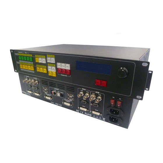
2.Hardware Orientation VSP 737 Rear Panel VSP 737 Rear Panel The figure below illustrates the professional interface and control signals of VSP 737 rear panel. INTERFACE INTERFACE 1~4.9~12 CVBS Input 14.16.22.24 VGA Input Dial Switch 17.20 USB Input 10/100M Interface... -
Page 25: 13.15.21.23: Hdmi Input Interface
2.Hardware Orientation VSP 737 Rear Panel 13.15.21.23: HDMI Input Interface HDMI 1/2/3/4 Input interface. Support HD Player, DVD, computer video signals and resolution: SMPTE:1080P50, 1080P59.94/60,1080i50,1080i59.94/60, 720p50, 720p59.94/60, 625/25/50 PAL, 525/29.97/59.94 NTSC, VESA:800×600×60Hz, 1024×768×60Hz, 1280×768×60Hz, 1280×1024×60Hz, 1600×1200×60Hz, 1920×1080×60Hz. Note HDMI1~4 standard DVI-I interface,compatible HDMI;... -
Page 26: 19: Program Output Interface
2.Hardware Orientation VSP 737 Rear Panel Support Resolutions: 800x600_60Hz, 1024x768_60Hz, 1280x768_60 Hz, 1280x1024_60 Hz, 1366x768_60 Hz, 1440x900_60_nr Hz, 1440x900_60 Hz, 1600x1200_60 Hz, 1600x1200_60_r Hz, 1920x1080_60 Hz, 1440x900_60_nr Hz and 1600x1200_60_r Hz is the lowest resolution; Output Interface 19: Program Program output interface can connect with next displayer or send signal to LED through sending card. -
Page 27: Switch And Power
2.Hardware Orientation VSP 737 Rear Panel Switch and power 25. Power Interface AC 90-264V 3.8A 50/60Hz IEC-3 Switch interface Switch Interface VSP 737 User Manual... -
Page 28: Vsp 737 Front Panel
VSP 737 Front Panel Insert power cord and push power to ON position. LCD module on the front panel will show RGBLINK and go into self verification before it load last setting and send processed image to the target monitor. For the first setup, DVI input is default source. - Page 29 2. Hardware Orientation VSP 737 Front Panel Keyboard Operation Into the Cycle : When into the cycle, it shows the current input format, preview the current output format, the current software information and the current device serial number. User who has the device serial number will acquire more effective service and support.
-
Page 30: Buttons
2. Hardware Orientation VSP 737 Front Panel Keyboard Operation Buttons Introduction: BG A:Key of background layer A lights on, background layer A is selected; light blinks, background layer A is editable; BG B: Key of background layer B lights on, background layer B is selected;... - Page 31 2. Hardware Orientation VSP 737 Front Panel Keyboard Operation function. Details are in: How to use the funtion of color key extraction. Full screen:Tap the key, the current layer picture is showed on full screen; blinking key of either Layer A or Layer B is the current layer.
- Page 32 2. Hardware Orientation VSP 737 Front Panel Keyboard Operation SAVE 1~10 light on together, select the wanted key, e.g. Select 1: Details are in: How to save parameter. Tap the key to load the saved user data; when the key lights on, keys of...
- Page 33 2. Hardware Orientation VSP 737 Front Panel Keyboard Operation Details are in: Output Format menu. Screen Parameter:Set it to the size of LED screen. After setting the Scale of picture, tap Reset, the current size of the picture is set as screen parameter.
- Page 34 2. Hardware Orientation VSP 737 Front Panel Keyboard Operation Note Scale and Crop function is mainly for Preview adjustment, Program output is always on full screen. User can easily change the size and position of screen via change the numeric values of screen, mainly for LED large screen user.
-
Page 35: Knobs
2. Hardware Orientation VSP 737 Front Panel Keyboard Operation Details are in: MENU. Next: Push to confirm the current choice. Knobs Run up and down to select the menu of LCD. LCD Panel It is for displaying the interactive menu between keys and communication. -
Page 36: Hardware Installation
Hardware Installation In This Chapter This chapter provides comprehensive installation instruction for VSP hardware: ollowing is the size of VSP 737 for your reference. VSP 737 User Manual... -
Page 37: Safety Precautions
Unpacking and Inspection Before opening VSP 737 process shipping box, inspect it for damage. If you find any damage, notify the shipping carrier immediately for all claims adjustments. As you open the box, compare its contents against the packing slip. -
Page 38: Menu Introduction
Menu Introduction In This Chapter This chapter describes all VSP 737 processor menus, including how they are accessed, the functions that are available, and descriptions of each menu tree (in block diagram format). The following topics are discussed: • Output Format •... -
Page 39: Output Format
Output Format Output Format Output format selection, press this button into current format and change the format through rotary switch. VSP 737 supports ten output formats as followings: Details are in: How to adjust output resolution VSP 737 User Manual... -
Page 40: Screen Parameter
Scale setting to make the picture displayed on screen fully. Screen parameter setting includes setting LED screen‘s width, height, X start point and Y start point. VSP 737 User Manual... -
Page 41: Move Setup
LCD instructions and Preview output red frame; Move:After Move Setup setting, tap the Move key, key lights on, the effect setting is finished and ready for switchover. Details are in: How to set picture fly-in-and-out effect.. VSP 737 User Manual... -
Page 42: Crop
User can rotate the knob to crop the current layer picture on its cropped position and size. The blinking key of either LAYER A or LAYER B is the selected layer picture. Details are in: How to crop input picture. VSP 737 User Manual... -
Page 43: Scale
User can easily set the position and size of screen via setting the screen parameter. It is mainly for LED large screen user. Details are in: How to adjust the size and position of output picture. VSP 737 User Manual... -
Page 44: Wipe
4.Menu Orientation WIPE WIPE Press the button to enter Effects Configuration Menu and multiple effects are available. VSP 737 User Manual... - Page 45 4.Menu Orientation WIPE VSP 737 User Manual...
-
Page 46: Menu
Rotate the left-right knob to select the right or left menu item; When a menu item has a * sign in front, the item is selected. Tap NEXT to go into the item for adjusting or viewing, the first line is the device named: VSP 737. VSP 737 User Manual... - Page 47 4.Menu Orientation MENU VSP 737 User Manual...
-
Page 48: Menu
DE H Start: Set on horizontal ordinate; DE V Start: Set on vertical ordinate; DE Width: Set on width; DE Height: Set on height; If the screen picture shows black edging, user can adjust it via this VSP 737 User Manual... -
Page 49: Menu
Press Menu to go back main menu and use the Knob button and Next to go into Crop setting sub menu to go into Scale: Scale Width; Scale Height; Scale Pos X; Scale Pos Y; Note The same operation can set Scale. VSP 737 User Manual... -
Page 50: Menu
USB Play State: It is to set the playing state or stopping state of USB input signal. MENU ---Picture Tap MENU to go back to homepage, flip over the homepage and select Picture setting; Tap NEXT to go into Picture setting for adjusting picture quality, it includes: VSP 737 User Manual... -
Page 51: Menu
Run knob switch and select AB Mode; Stretch includes: CUT Switch wipe right, wipe left, wipe up, wipe down, wipe center out, wipe curtain out, wipe square out etc. And DISSOVLE Switch VSP 737 User Manual... -
Page 52: Menu
COLOR setting. The device provides 8 colors for choices as shown above. MENU ---Video FU User can update the image firmware via USB1~USB4 port. MENU ---Matrix Press Menu to go back to main menu and use the Knob button and Next VSP 737 User Manual... - Page 53 Matrix: It can save other any channel in channel 1, such as the red display above. Motioned for: the channel 2 signal copy to channel 1, the orange display motioned for the channel 3 signal copy to channel 2. VSP 737 User Manual...
-
Page 54: System Setup And Operation
How to use Color key extraction function How to use caption adder function How to use blending function How to set picture-in-and-out effect How to save setting parameter How to load saved parameters VSP 737 User Manual... -
Page 55: How To Setup The Device
DVI/VGA port. Outputting signals via DVI-I (Use normative DVI-I port for Preview; Compatible with VGA output, change over VGA output via terminals.) Output resolutions are as below: 800x600_60Hz, 1024x768_60Hz, 1280x768_60 Hz, 1280x1024_60 Hz, 1366x768_60 Hz, 1440x900_60_nr Hz, 1440x900_60 Hz, 1600x1200_60 Hz, 1600x1200_60_r Hz, 1920x1080_60 Hz VSP 737 User Manual... - Page 56 5. System setting and operation How to setup the device 19. Program DVI1 output is the default main image of the system, it mainly connects large screen sending card, current VSP 737 supports resolutions as below: 800x600_60Hz, 1024x768_60Hz, 1280x768_60 Hz,...
-
Page 57: How To Confirm The Device Is In Normal Operation
2. Device is on self-checking, the fan works, keys light on in turns; 3. Device starts system, LCD screen shows as below: RGBLINK 视诚科技 亮彩系列 AVDSP Series VSP 737 WAIT INIT NETWORK… I WAIT INIT NETWORK… FINISH NETWORK HDCP FALLLED IP ADDRESS IP: 192.168.0.100... - Page 58 4. Factory parameter or Save 1 parameter is the default starting system of the device, some of the keys light on, LCD screen shows as below: RGBLINK SN: **** LAYER A:DVI1 ****x**** x** LAYER B:DVI2 SOFTWARE VERSION ****x**** x** OUT FORMAT: 1024x768x60 VSP 737 User Manual...
-
Page 59: How To Preview Input Signals
6. Preview Layer B input The same as background operation, tap Layer B,then tap PRG,Layer B input signal is the corresponding numbers of VGA2 DVI2 CV3 CV4 USB1, tap the keys to preview Layer B signal source. VSP 737 User Manual... -
Page 60: How To Adjust Output Resolution
2. LCD screen shows: OUTPUT FORMAT >1024x768x60 3. Rotate the knob and select corresponding resolution, tap NEXT to confirm. Note Current VSP 737 supports resolutions as below: 800x600_60Hz,1024x768_60Hz,1280x768_60 Hz, 1280x1024_60 Hz,1366x768_60 Hz, 1440x900_60_nr Hz,1440x900_60 Hz, 1600x1200_60 Hz, 1600x1200_60_r Hz, 1920x1080_60 Hz. VSP 737... -
Page 61: How To Adjust Output Resolution
4. Rotate the knob again to adjust picture height, picture X position, picture Y position, tap NEXT to confirm; SCALE HEIGHT B: >1024 SCALE POS X B: >0 SCALE POS Y B: >0 Note System default picture start point(0,0) locates at top left corner. VSP 737 User Manual... -
Page 62: How To Crop Input Pictures
4. Rotate the knob again to adjust cropped picture‘s height, crop picture X position and Y position, tap NEXT to confirm; CROP HEIGHT B: >1024 CROP POS X B: >0 CROP POS Y B: >0 Note System default picture start point(0,0) locates at top left corner. VSP 737 User Manual... -
Page 63: How To Realize Single Picture Signals Switching
Tap corresponding key of CV4 to preview CV4 signal source; Tap corresponding key of USB2 to preview USB2 signal source; 3. After previewing needed signal source, tap PRG, key lights off, preview functions off, tap switching key to switch over and output preview signal source; VSP 737 User Manual... -
Page 64: How To Realize Dual Pictures Adjusting Function
CUT or other shift keys to switch over back to Preview output, then it is editable. Note Once edited dual pictures‘ size and position is switch over to Program output, it cannot be edited again. VSP 737 User Manual... -
Page 65: How To Select Effects Switching
Operation is as below: 1. Tap for Pull-screen effect: SETUP WIPE MODE: >WIPE HARD SWITCH SETUP WIPE MODE: >WIPE SOFT SWITCH 2. Rotate the knob to select needed pull-screen effect and speed: WIPE MODE: >WIPE UP WIPE SPEED: >8 VSP 737 User Manual... - Page 66 5. System setting and operation How to select effects switching for fade-in-fade-out effect: DISSOLVE DURATION: >1.5S 2. Rotate the knob to select needed effect and speed; (0.5-30S) VSP 737 User Manual...
-
Page 67: How To Set Input Matrix
3. Tap NEXT to go into Layer A or Layer B settings; *LAYER A >INPUT 1 *LAYER B >INPUT 2 4. Tap NEXT to go into Layer A or Layer B input settings; >LAYER A *INPUT 1 >LAYER B *INPUT 2 VSP 737 User Manual... -
Page 68: How To Use Background
2. Tap PRO to edit on background; BGA‘s corresponding signal channels are:VGA3,DVI3,CV5,CV6, USB3 BGB‘s corresponding signal channels are:VGA4,DVI4,CV7,CV8, USB4 3. BGA or BGB key lights on, tap Clear layer to clear background signal, key lights off, signal clearing is finished; VSP 737 User Manual... -
Page 69: How To Use Black
BLACK signal realizes one-key-touch to a black screen. VSP737‘s BLACK provides effect processing on Program output, BLACK uses fade-in-fade-out effect. Operation is as below: 1. Just tap BLACK key, then Program output turns to BLACK with fade-in- fade-out effect; E.g. as pictures below: VSP 737 User Manual... -
Page 70: How To Use Inside Test Pictures
>VSP737 *BG COLOR VIDEO FU 5. Tap NEXT to go into BG COLOR menu; BG COLOR *BLACK 6. Rotate the knob to adjust color and tap NEXT to confirm. Note System defaults 8 pure color pictures. VSP 737 User Manual... -
Page 71: How To Use Color Key Extraction Function
KEY STEUP >POSITION 6. Rotate the knob to select RANGE redundancy value setting, (0-255) is the range for color key extraction function. KEY STEUP >RANGE VSP 737 User Manual... -
Page 72: How To Use Caption Adder Function
>INPUT VALUE KEY TYPE >CAPTURE VALUE 5. Rotate the knob, select CAPTURE VALUE sample color value, top right corner appears a cursor, move the cursor for this function; moving cursor position menu is: KEY SETUP >POSITION VSP 737 User Manual... - Page 73 5. System setting and operation How to use caption adder function 6. Rotate the knob to select RANGE redundancy value adjusting function; (0~255) is the range for caption adding function; KEY STEUP >RANGE VSP 737 User Manual...
-
Page 74: How To Use Blending Function
3. Rotate the knob, adjust blending width value (0~255), the larger the value, the more the blended edge, and the smaller the value, the less the blended edge. LCD screen shows as below: BLENDING: ON >WIDTH: Reference picture: VSP 737 User Manual... -
Page 75: How To Set Picture-In-And-Out Effect
, key lights off, MOVE SETUP functions off, LCD screen shows: CLEAR MOVE SETUP Note Apply together to realize MOVE SETUP, after tapping , assure key lights on without blinking, or else key is not editable. VSP 737 User Manual... -
Page 76: How To Save Setting Parameter
CP2048 ‗s 36 groups of savings; Operations as below: 1. Tap SAVE; 2. Keys 1,2,3,4,5,6,7,8,9,10 light on at the same time; 3. Select the wanted key and tap it, LCD screen shows the saving process; Picture 1:Go into the saving mode VSP 737 User Manual... -
Page 77: How To Load Saved Parameters
3. Select the wanted saving parameter, tap its corresponding key to blinking state; 4. User can recall the configuration one by one; 5. Tap LOAD again to exit loading saved parameters state; Picture 1:Go into Loading saved mode VSP 737 User Manual... -
Page 78: Specification
Standard DVI-I socket Supported Resolutions SMPTE:625/25/50 PAL, 525/29.97/59.94 NTSC, 1080P50,1080P59.94/60,1080i50,1080i59.94/60, 720p50,720p59.94/60 VESA:800×600×60Hz,1024×768×60Hz,1280×768×60Hz, 1280×1024×60Hz,1600×1200×60Hz,1920×1080×60Hz Signal Level TMDS pwl, single pixel input,165MHz bandwidth Format Standard HDMI 1.3 Background Number of Inputs Connector Standard DVI-I socket VESA:1024×768×60Hz,1280×768×60Hz, Supported Resolutions VSP 737 User Manual... - Page 79 Transition effects Fade in and fade out switching between any two inputs Extras Communication RS232 USB TCP/IP Power Supply 85-264V 2.1A IEC-3 Working Environment 0° C~45° C Stored Environment 10% to 90% Product Warranty 3-year labor warranty VSP 737 User Manual...
-
Page 80: B.contact Information
3-year parts and labor warranty. Warranties are effective upon delivery date to customer and are non-transferable. RGBlink warranties are only valid to the original purchase/owner. Warranty related repairs include parts and labor, but do not include faults resulting from user negligence, special modification, lighting strikes, abuse(drop/crush), and/or other unusual damages. -
Page 81: C.firmware Upgrading
C.Firmware Upgrading Upgrade of Function Firmware 1. Firstly,install the control software in your PC; 2. Input VSP 737 firmware upgrade network address in address toolbar: 192.168.0.100, then enter the user name ―admin‖ and password ―rgblink123‖ in the dialog box. 3.Click FPGA Upgrade to enter the upgrade page;... - Page 82 5. Click 【 Update】 to upgrade, if LCD screen shows: UPGRADE SUCCESS, PLEASE RESTART, upgrade is finished; if not, operate again. 6. After upgrade is finished, restart the device to check if the operation works normally or not. VSP 737 User Manual...
-
Page 83: Upgrade Of Picture Firmware
4. ―Update Main Board Update Success‖ means upgrade is finished, change to upgrade another USB port, operations are the same as the above; 5. Power off and power on again to check if the device works normally. VSP 737 User Manual... - Page 84 Firstly, choose the right serial port, set the Baud rate to 115200, choose LPC2368, and load the aiming document (hex. file) of 100M IP board upgrade software; Secondly, tick the item below to confirm. Finally, click the ―start‖ button. VSP 737 User Manual...
- Page 85 After downloading, exit the program, power off the device, tack the two coding switches back (as picture shows below), restart the device, and check if the device works normally or not. Note Flash Magic download website: http://www.flashmagictool.com/download.html&d =FlashMagic.exe VSP 737 User Manual...
Need help?
Do you have a question about the VSP 737 and is the answer not in the manual?
Questions and answers