Advertisement
–
For full installation, configuration, and operation details, refer to the
NOTE
VSP 628 user manual, which is available at www.rgblink.com.
This guide provides quick start instructions for an experienced installer
to set up and operate the VSP 628.
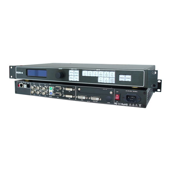
Installation and cabling features
Rear Panel
Connections
1
Small push button
2
10/100M Interface
3
USB Interface
RS232 Interface
4
5
~
7
CVBS Input
8
S-Video DIN 4
9
VGA Input
10
DVI Input
11 12
Gigabit copper port
13
Power supply port of sending card
14
USB control port of sending card
Step 1-Mounting
Turn off or disconnect all equipment power sources.
Step 2-CVBS Input
Connect NTSC, PAL or SECAM component
video to these female BNC connectors.
Step 3-S-Video Input
Used to input S-Video signal (PAL, NTSC,
SECAM compatible)
Step 4-VGA Input
Input through computer or VGA
source (compatible with YPBPR).
Step 5-DVI Input
DVI are used to connect the video
sources from HDD media player,
DVD player and computer.
Step 6-SDI Input
Can receive signal from HD player and
HD camera.
Address: S603-604 Weiye Building Torch Hi-Tech Industrial Development Zone, Xiamen, Fujian Province, P.R.C
Tel: 00865925771197
Email: rgblinkcs@gmail.com
DVI Input
15
SDI Input
16
17
SDI Loop Out
18
~
20
CVBS Loop Out
S-Video Loop Out
21
22
VGA Loop Out
DVI Loop Out
23
DVI Output
24
25
DVI+VGA DVI Output
26
CVBS Output
27
Switch
28
Power
Fax:00865925771202
http://www.rgblink.cn
Step 7-SDI Loop Out
Can connect the next level VSP 628 or the device
with SDI input.
Step 8-CVBS Loop Out
Can connect the next level VSP 628 or the device
with CVBS input.
Step 9-S-Video Loop Out
Can connect the next level VSP 628 or the device
with S-Video loop out.
Step 10-VGA Loop Out
Can connect the next level VSP 628 or the device
with VGA input.
Step 11-DVI Loop Out
Can connect the next level VSP 628 or the device
with DVI input.
VSP 628 Quick Start
Rev 1.1
Page 1 of 7
Advertisement
Table of Contents

Related Manuals for RGBlink VSP 628


Summary of Contents for RGBlink VSP 628
- Page 1 Turn off or disconnect all equipment power sources. Step 7-SDI Loop Out Step 2-CVBS Input Can connect the next level VSP 628 or the device Connect NTSC, PAL or SECAM component with SDI input. video to these female BNC connectors.
- Page 2 Step 12-Program Output Step 18-Power Used to connect with DVI-based Plug in power cord which has IEC connector, VSP 628 display or LED control display. support AC power from 85 to 265VAC, 50-60Hz, which Step 13-Preview Output means world wide compatible.
- Page 3 For different channel, the output picture size and About how to install this NOTE position may be different, VSP 628 can realize different software in the WINDOWS operating channel image size and position arbitrarily regulating. system, please refer to the user manual 1).
-
Page 4: Step 7-Factory Reset
Address: S603-604 Weiye Building Torch Hi-Tech Industrial Development Zone, Xiamen, Fujian Province, P.R.C VSP 628 Quick Start Tel: 00865925771197 Fax: 00865925771202 Rev 1.1 Email: rgblinkcs@gmail.com http://www.rgblink.cn... -
Page 5: Step 1-Set Up Communication
IP address. VSP 628 w i l l a u t o m a t i c a l l y u p d a t e the o u t p u t If users use other device, they need to install webkit kernel browser, such as: apple Safari, Google Chrome resolution. -
Page 6: Step 3-Input Signal Switching
2. For and position easily through "-+" icon. Click "Set" after example, you can switch "Input" icon in title bar to modify the digital, VSP 628 image will display the choose image 2 input source. latest Settings;... -
Page 7: Step 7-Other Setting
Key Lock: If slide block is gray, it is unlock, and VSP 628 keys can normally operate; And if slide block is green, the VSP 628 keys lock, and user can't operate any button. Dimmer: ALPHA transparency regulation. Drag ball to change the transparency value, transparency value is between 0 ~ 100 levels.
Need help?
Do you have a question about the VSP 628 and is the answer not in the manual?
Questions and answers