
Related Manuals for RGBlink VSP3500


Summary of Contents for RGBlink VSP3500
-
Page 1: User Manual
VSP 3500 User Manual Manual #: RGB-RD-UM-V3500 E001 Revision: V1.0 VSP 3500 User Manual... - Page 2 Co.,LTD. No part can be copied, reproduced or translated without permission. Notice RGBlink provides this manual ―as is‖ without warranty of any kind, no matter expressed or implied, including but not limited to the implied warranties or merchantability and fitness for a particular purpose. RGBlink may make improvements or changes to the products and the programs described in this publication at any time without notice.
- Page 3 30 days after the transfer of risks. In the event of justified notice of compliant, RGBlink can repair the fault or provide a replacement at its own discretion within an appropriate period.
- Page 4 Company Address Xiamen RGBlink Science & Technology Co., Ltd. Headquarter: S603~604 Weiye Building Torch Hi-Tech Industrial Development Zone Xiamen, Fujian Province, P.R.C Shenzhen office: Floor 11, A1 Building, Baiwang R&D Building, Shahe West Road, Xili Town, Nanshan District, Shenzhen, Guangdong Province, P.R.C...
-
Page 5: Power Source
Operators Safety Summary The general safety information in this summary is for operating personnel. Do Not Remove Covers or Panels There are no user-serviceable parts within the unit. Removal of the top cover will expose dangerous voltages. To avoid personal injury, do not remove the top cover. - Page 6 Terms In This Manual and Equipment Marking WARNING Highlights an operating procedure, practice, condition, statement, etc, which, if not strictly observed, could result in injury or death of personnel. Note Highlights an essential operating procedure, condition or statement. CAUTION The exclamation point within an equilateral triangle is intended to alert the user to the presence of important operating and maintenance (servicing) instructions in the literature accompanying the appliance.
- Page 7 Change History The table below lists the changes to the Video Processor User Manual. Format Time ECO# Description Principal 2013-07-11 0000 Release Vira VSP 3500 User Manual...
-
Page 8: Table Of Contents
CONTENT CONTENT ..................8 1. Introduction ................. 15 Chapter Structure ..................16 How to Use This Guide ................17 Terms and Definitions ................. 18 System Overview ..................23 Application Question .................. 24 2. Hardware Orientation ..............25 In This Chapter .................... 25 VSP 3500 Back Panel ................... - Page 9 Switch and Power ....................27 13. Switch ......................28 14. Power Port ....................28 VSP 3500 Front Panel .................. 29 Number Keys ..................... 29 Layers ........................29 Inputs ........................29 Outputs ........................ 29 Layer Functions ....................30 Split Mode ......................30 Custom Adjustments ..................
- Page 10 Knob Part ......................43 LCD Panel Part ....................43 3. Hardware Installation ..............44 In This Chapter .................... 44 Safety Precautions ..................45 Unpacking and Inspection ................45 Site Preparation ..................45 4. Menu Orientation ................ 46 In This Chapter .................... 46 MENU ......................
- Page 11 Language Selection ..................58 Connection ......................59 Mode Settings ....................62 Output Settings ....................62 Alpha Settings ....................63 Alpha Speed Settings ..................63 Color Key Settings .................... 63 Layer Settings ....................64 Input Port Settings ..................... 65 Scale Settings ....................65 Crop Settings .....................
- Page 12 Factory reset ...................... 75 Language ......................75 Management ...................... 75 Advanced Test ....................75 Script ........................76 Load Customer Script ..................76 Save Customer Script ..................76 Version Explain ....................76 About ........................76 Image Display Toolbar ..................77 Information Toolbar ................... 77 How to control processor through RS232? ..........
- Page 13 How to set the position of layer image? ............. 93 How to achieve split function? ..............94 How to achieve quick split? ................. 96 How to set picture size in split effects? ............98 How to rotate layer image? ................. 99 How to save the current setting parameters? ...........
- Page 14 B.Contact Information ..............107 C. Upgrading Software ..............108 Main board MCU program upgrading steps ..........108 VSP 3500 User Manual...
-
Page 15: Introduction
Introduction This chapter is designed to introduce you to the VSP 3500 User Manual. Areas to be covered are: Chapter Structure How to Use This Guide Terms and Definitions System Overview Application Questions VSP 3500 User Manual... -
Page 16: Chapter Structure
1. Introduction Chapter Structure Chapter Structure The following chapters provide instructions for all aspects of VSP 3500 operations: Chapter 1 Introduction Chapter 2 Hardware Orientation Chapter 3 Hardware Installation Chapter 4 Menu Orientation Chapter 5 Communication Software Guideline Chapter 6 System Setup and Operations Chapter 7 Common Questions and Solution... -
Page 17: How To Use This Guide
1.Introduction How to Use This Guide How to Use This Guide Following are important tips for streamlining your use of this User Manual in its electronic ―PDF‖ form. Navigating Use Acrobat Reader’s ―bookmarks‖ to navigate to the desired location. All chapter files have the same bookmark structure for instant navigation to any section. -
Page 18: Terms And Definitions
1. Introduction Terms and Definitions Terms and Definitions The following terms and definitions are used throughout this guide; “ASCII”: American Standard for Information Interchange. The standard code consisting of 7-bit coded characters (8 bits including parity check) used to exchange information between data processing systems, data communication systems, and associated equipment. - Page 19 1. Introduction Terms and Definitions color temperature for the A/V industry include 5000° K, 6500° K, and 9000° K. “Contrast ratio”: The radio of the high light output level divided by the low light output level. In theory, the contrast radio of the television system should be at least 100:1, if not 300:1.
- Page 20 1. Introduction Terms and Definitions algorithm standards that allow digital compression, storage and transmission of moving image information such as motion video, CD-quality audio, and control data at CD-ROM bandwidth. The MPEG algorithm provides inter-frame compression of video images and can have an effective compression rate of 100:1 to 200:1.
- Page 21 1. Introduction Terms and Definitions display device, the color control adjusts the saturation. Not to be confused with the brightness, saturation is the amount of pigment in a color, and not the intensity. Low saturation is like adding white to the color.
- Page 22 1. Introduction Terms and Definitions can be attached or detached without removing computer power. The number of devices being designed for USB continues to grow, from keyboards, mice, and printers to scanners, digital cameras, and ZIP drives. “VESA”: Video Electronics Standards Association. A nonprofit number organization dedicated to facilitating and promoting personal computer graphics through improved standards for the benefit of the end-user.
-
Page 23: System Overview
1. Introduction System Overview System Overview The VSP 3500 is a dedicated seamless Video Wall Processor and it does have some features not found on any other models that make setup easier. VSP 3500 offer the advantage that when basic video wall control is not required, it can be used for scaling applications, and can setup as rotary possibility. -
Page 24: Application Question
1. Introduction Application Question Application Question We offer solutions to demanding technical problems. Any application questions, or required further information, please contact with our Customer Support Engineers. Refer to Appendix B for contact details. VSP 3500 User Manual... -
Page 25: Hardware Orientation
Hardware Orientation In This Chapter This chapter provides detailed information about the VSP 3500 hardware. The following topics are discussed: VSP 3500 Back Panel VSP 3500 Front Panel VSP 3500 Front Panel Button Part VSP 3500 User Manual... -
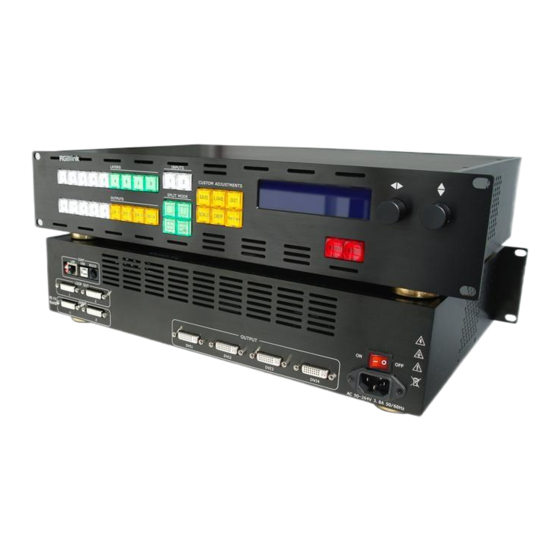
Page 26: Vsp 3500 Back Panel
2. Hardware Orientation VSP 3500 Back Panel VSP 3500 Back Panel The figure below illustrates the professional interface and control signals of VSP 3500 back panel: INTERFACE INTERFACE Dial switch DVI Loop Out 10/100M Interface DVI Input USB Interface 9~12 DVI Output RS232 Interface 13.14... -
Page 27: 5.6: Dvi Loop Out
2. Hardware Orientation VSP 3500 Back Panel Note DVI1,2 applies the standard DVI-I port, and is compatible with HDMI1.3. 5.6: DVI Loop Out DVI loop out, can connect the next level VSP 3500 or the device with DVI loop out. OUTPUT 9~12: DVI Output DVI output. -
Page 28: 13. Switch
2. Hardware Orientation VSP 3500 Back Panel 13. Switch Switch on. It means power on; Switch off. It means power off. 14. Power Port AC 90-264V 50/60Hz IEC-3 power interface VSP 3500 User Manual... -
Page 29: Vsp 3500 Front Panel
2. Hardware Orientation VSP 3500 Front Panel VSP 3500 Front Panel Brief introduction of its front panel as the following picture: 1~10 Number Keys CUSTOM ADJUSTMENTS LAYERS Control Button INPUTS LCD Panel OUTPUTS Knob SPLIT MODE Number Keys Number keys 0 ~ 9 is used to save and load, and input the required number for SCALE, CROP, and POSITION directly. -
Page 30: Layer Functions
2. Hardware Orientation VSP 3500 Front Panel For details, please confer to: Outputs Part. Layer Functions Buttons LAYER FUNCTIONS is used for program layer A, B, C, D. For details, please confer to: Layer Functions Part. Split Mode Used for split effects output. For details, please confer to: Split Mode Part. -
Page 31: Vsp 3500 Front Panel Button Part
Plug power and push to ON. LCD module on the front panel will show RGBLINK and go into self verification before it load last setting config and send processed image to the target monitor. For the first setup, DVI input is default source. - Page 32 User have the device serial number will acquire more effective service and support. IN1:1024 x768 x60 IN2:1280 x768 x60 OUT:1920x1080x60 视诚科技 RGBlink IP:192.168.0.100 VSP 3500 VER 3.6 VSP 3500 User Manual...
-
Page 33: Number Keys Part
2. Hardware Orientation VSP 3500 Front Panel Button Part Number Keys Part 1: Number Key 1. Press SAVE, LOAD, SCALE, CROP and POSITION key, The light lights, user can choose SAVE to 1 or LOAD from 1, or input number 1 directly. 2: Number Key 2. -
Page 34: Layers Part
2. Hardware Orientation VSP 3500 Front Panel Button Part 7: Number Key 7. Press SAVE, LOAD, SCALE, CROP and POSITION key, The light lights, user can choose SAVE to 7 or LOAD from 7, or input number 7 directly. 8: Number Key 8. Press SAVE, LOAD, SCALE, CROP and POSITION key, The light lights, user can choose SAVE to 8 or LOAD from 8, or input number 8 directly. -
Page 35: Inputs Part
2. Hardware Orientation VSP 3500 Front Panel Button Part B: Layer B. It lights means being selected and brinks means can be programmed; C: Layer C. It lights means being selected and brinks means can be programmed; D: Layer D. It lights means being selected and brinks means can be programmed;... -
Page 36: Outputs Part
2. Hardware Orientation VSP 3500 Front Panel Button Part Outputs Part VSP 3500 supports 4 outputs. OUTPUTS buttons DVI1, DVI2, DVI3, DVI4 are corresponding to the output ports DVI1, DVI2, DVI3, DVI4 in back panel. Button lights show its corresponding output are selected. For details, please refer to: How to edit and define outputs? Note... -
Page 37: Split Mode Part
2. Hardware Orientation VSP 3500 Front Panel Button Part Split Mode Part Split effect button, press it and it lights, it can achieve split effects, that is VSP 3500 4 outputs are in the form of output split. Single equipment can be set at max,: 2048x4*1152 or 2048*1152x4 or 2048x2*1152x2, it is mainly suitable for LED screen users. - Page 38 2. Hardware Orientation VSP 3500 Front Panel Button Part Split Mode 2: HORIZONTAL 1/2 Split Mode 3: FIELD GLYPH Other split modes, including the following: Split Mode 4: VERTICAL 1/2 VSP 3500 User Manual...
- Page 39 2. Hardware Orientation VSP 3500 Front Panel Button Part Split Mode 5: HORIZONTAL 1/4 Split Mode 6: VERTICAL 1/4 Split Mode 7: 2 IN 3 OUT VSP 3500 User Manual...
-
Page 40: Custom Adjustments Part
2. Hardware Orientation VSP 3500 Front Panel Button Part Split Mode 8: 2 IN 4 OUT Custom Adjustments Part CUSTOM ADJUSTMENTS set function shortcut button for users, shortcut button is the most commonly used functions for users , shortcut setting the most frequent use function for the convenience of customers operate. - Page 41 2. Hardware Orientation VSP 3500 Front Panel Button Part SAVE >SAVE TO 1~10 SAVE TO 1 SAVE FINISH Load: press the button to load the saved user data, and meanwhile button 0~9 light, choose the corresponding position to load. LOAD FROM 1~LOAD FROM 9 corresponding button 1~9, LOAD FROM 10 corresponding button 0.
-
Page 42: Control Button Part
2. Hardware Orientation VSP 3500 Front Panel Button Part Users can change the screen size and position easily by changing the digital setting parameters. It is mainly suitable for the LED large screen users. CROP: Crop button, press it and it lights, users can crop the current selected layer image through the up-down and left-right sides knob, and can adjust the crop position, size, the current selected layer is subject to button A, B, C, D. -
Page 43: Knob Part
2. Hardware Orientation VSP 3500 Front Panel Button Part CONFIG, OUTPUT CONFIG, LAYER CONFIG, RESET. Users can adjust the needed install option combined with knob according to need. Confirm button or lower key, press the key to confirm options or enter-out the current options. -
Page 44: Hardware Installation
Hardware Installation In This Chapter This chapter provides comprehensive installation instruction for VSP 3500 hardware: Following is the size of VSP 3500 for your reference: VSP 3500 User Manual... -
Page 45: Safety Precautions
Safety Precautions For all VSP 3500 processor installation procedures, please observe the following important safety and handling rules to avoid damage to yourself and the equipment. To protect users from electric shock, ensure that the chassis connects to earth through the ground wire provided in the AC power Cord. ... -
Page 46: Menu Orientation
Menu Orientation In This Chapter This chapter describes all VSP 3500 processor menus, including how they are accessed, the functions that are available, and descriptions of each menu tree (in block diagram format). The following topics are discussed: • MENU ... -
Page 47: Menu
4. Menu Orientation MENU MENU Press MENU button to enter the main MENU; Rotate UP/DOWN knob to browse level 1 menu; Press NEXT to level 2 menu. Repeat above operations can access to level 3 and level 4 menu ; Rotate LEFT/RIGHT knob to set and adjust for the current menu;... -
Page 48: Dev Info
4. Menu Orientation MENU DEV INFO Select Dev Info, pressing NEXT, It will show the information of input and output video signals. As picture above, running the knob switch can check preview output format, output format, program version, the current device IP address and baud rate;... -
Page 49: Output Config
4. Menu Orientation MENU 1680x1050x60_r,1400x1050x60_r. AUTO DETECT: Auto detect input resolution, this option general choose ON open state, users will not need to choose manually, the equipment will read input resolution automatically. Note The system is default for ON state; COLOR SPACE: Color space choice, specific includes 4 kinds as follows: Note When the image color of input signal source... - Page 50 4. Menu Orientation MENU LEFT/RIGHT knob to set the following options separately: OUTPUT FORMAT: Output resolution choice, VSP 3500 support 12 kinds of common and other for total 17 resolutions, specific as follows: 1024x768x60,1280x720x60, 1280x768x60, 1280x1024x60,1360x768x60, 1366x768x60,1400x1050x60, 1440x900x60, 1440x900x60_r, 1600x1200x60, 1600x1200x60_r,1680x1050x60, 1680x1050x60_r, 1920x1080x60, 1920x1080x60_r, 1920x1200x60,2048x1152x60.
-
Page 51: Layer Config
4. Menu Orientation MENU LAYER CONFIG SET INPUT: Input selection, you can choose needed programming input 1, 2, after choosing, you can set display, rotate. DISPLAY: Display Setting, you can set LIVE or FREEZE, H Mirror or V Mirror switch. SET ROTATE: Rotate Setting, you can set image rotation and choose the image rotate to LEFT or rotate to RIGHT, and also can choose to OFF image rotation function. -
Page 52: System
4. Menu Orientation MENU 2~128. SIGNAL BACKUP: Signal back up, user can choose ON/OFF. If one channel signal interrupted, the device will switch to next channel signal in ON station. DELAY CALL SAVE: Set delay the output time. When more than one equipment power on, and the processor is the end equipment in order to improve question that can’t identify the input signal and phenomenon that LED screen appear messy code and flash screen, now need to delay the... -
Page 53: Communication Software Guideline
Communication Software Guideline In This Chapter This chapter mainly introduce the control of communication software, mainly includes as follows: Install Software Run Software How to control processor through RS232? How to control processor with console software by USB? VSP 3500 User Manual... -
Page 54: Install Software
5. Communication Software Guideline Install Software Install Software VSP 3500 video processor is very easy to be configured with user friendly communication software, support drag and drop operation for edit and display. Also it can be customized with schedule function. Double click , to install, English version default for use, click ―select‖... - Page 55 5. Communication Software Guideline Install Software Users can choose installation path of the VSP 3500 PC software through the "Destination Directory", as shown in figure: VSP 3500 User Manual...
- Page 56 5. Communication Software Guideline Install Software Choose "Next" to continue installation, as shown in figure: Choose "Next" to continue installation, as shown in figure: VSP 3500 User Manual...
- Page 57 5. Communication Software Guideline Install Software Choose "Next" to continue installation, as shown in figure: Click ―Finish‖ and ready to run VSP 3500 console, as shown in figure: VSP 3500 User Manual...
-
Page 58: Run Software
5. Communication Software Guideline Run Software Run Software The user install VSP 3500 PC software in the random attached disk . Install the software to the specified directory according to the software prompt, the installation steps as follows: Run Software Double-click on the desktop shortcut to operate and control software , choose and double-click VSP 3500 control software interface as shown:... -
Page 59: Connection
5. Communication Software Guideline Run Software Connection Through the PC software to control video processor, the product is equipped with a control line that is serial lines by default (RS-232), end nine-pin port (DB9F), four-pin COM Crystal head at one end (6B4C), besides the power line. - Page 60 5. Communication Software Guideline Run Software After confirmation of serial port then open control software, find the 【Connection】tab, click to enter setup option: Software serial connection by default, when the user use at the first time, set the serial port; Interface left bottom display , after serial port setup finished, click the button...
- Page 61 5. Communication Software Guideline Run Software “How to control processor with PC software, concreteness can refer to: console software by USB?” Note RS 232 Serial line, all USB line can upgrade procedures. After USB connection or serial connection, click to search equipment, the equipment search and connect automatically.
-
Page 62: Mode Settings
5. Communication Software Guideline Run Software Mode Settings After confirm the equipment can communicate, you can use after you set up equipment display. set the 【 Mode 】 options in figure: Output Settings Set output way information, you can set output 1, 2, 3, 4 channel respectively;... -
Page 63: Alpha Settings
5. Communication Software Guideline Run Software Alpha Settings You can set the alpha value of each layer respectively (range in 0 ~ 128), when the transparency is 0, the layer image will not display, when the transparency is 128, the layer image display fully. Note The function is the same as MENU Output... -
Page 64: Layer Settings
5. Communication Software Guideline Run Software Available/close: Select and tick available option, the color key function open; Key in: Select color to remove; Key out: Select color to reserve; Red, green, and blue article regulation bar: Adjust color value of the color key. -
Page 65: Input Port Settings
5. Communication Software Guideline Run Software Input Port Settings VSP 3500 is multi-layer image processing, set all layer data in this interface, the layer data can configurate input way arbitrarily, namely, four layers can be configured to the same or different way data, and realize matrix function. -
Page 66: Crop Settings
5. Communication Software Guideline Run Software Note This set also can realize through the SCALE key Crop Settings You can set crop function to signal input image. The user can cut image by changing the number or click on the pull down arrow, or drag the edge of image. -
Page 67: Mirror Image And Test Pattern Settings
5. Communication Software Guideline Run Software Mirror Image and Test Pattern Settings There are two mirror modes, namely level image and vertical mirror; you can also choose test images; Note The function is the same as MENU Output Config Layer A Display Mirror. - Page 68 5. Communication Software Guideline Run Software Note The function is the same as MENU Output Config Layer A Set Rotate Switch Mode Settings Swap: After switch Cut/Take, Program input and Preview input, the image exchange. Stay: After switch Cut/Take, Program follow Preview input image. Note VSP 3500 version 1.0 is unavailable.
-
Page 69: Load User Mode
5. Communication Software Guideline Run Software Load User Mode Click on the loading user mode options, you can transfer to the user save information directly, the system provides 10 kinds of save modes for customers choose. Note This setting also can realize through Load key. Note Without electricity to restart, equipment loads user mode 1 automatically. -
Page 70: Split Screen Mode
5. Communication Software Guideline Run Software Note This setting also can realize through Save key. Split Screen Mode It provides 8 kinds of cascade modes for the user to choose. The corresponding rendering is listed below: VSP 3500 User Manual... -
Page 71: Cut
5. Communication Software Guideline Run Software Note This setting also can realize through keys in Split Mode area. Seamless switch button; Note VSP 3500 version 1.0 is unavailable. Take Seamless special effects switch button; VSP 3500 User Manual... -
Page 72: Input Config
5. Communication Software Guideline Run Software Note VSP 3500 version 1.0 is unavailable. Config Mode Input Config Click home page on the configuration, tick in the input configuration option, , it needn't to choose manually, the system can search the resolution of the input automatically, the other set terms is gray, namely, you needn't to set, equipment is the default settings, as the following graph: VSP 3500... - Page 73 5. Communication Software Guideline Run Software Note The choice of output resolution, the function is the same as MENU Input Config Input Input Format Output Config Click on the configuration mode page, users only need to select output resolution in the output configuration option, other settings items is gray, namely, when you needn't to set, equipment is the default settings, as the following graph: VSP 3500...
-
Page 74: Control
5. Communication Software Guideline Run Software Note The choice of output resolution, the function is the same as MENU Output Config Common Format Control IP Setting User can set IP through this function, and it often used for the same computer to operate a few devices at the same time or remote control. -
Page 75: Factory Reset
5. Communication Software Guideline Run Software Factory reset Click on the device factory initialization, all set back the factory value. Note The function is the same as Reset in the menu. Language Language choice; The software supports Chinese and English Management Advanced Test VSP 3500... -
Page 76: Script
5. Communication Software Guideline Run Software Note Advanced test only for engineers, please contact our customer personnel for the administrator password if you need; Script Load Customer Script The Users can input previous script and change the parameters. Save Customer Script Save the current script in operation to the specified path;... -
Page 77: Image Display Toolbar
5. Communication Software Guideline Run Software Image Display Toolbar Display the location, size and output resolution information of the current image. When the user modify parameters in the image toolbar, display image may change follow it. Information Toolbar VSP 3500 User Manual... - Page 78 5. Communication Software Guideline Run Software The bottom of Software connector displays software version, core board version, firmware version and product serial number of the current used device. VSP 3500 User Manual...
-
Page 79: How To Control Processor Through Rs232
5. Communication Software Guideline How to control processor through RS232? How to control processor through RS232? First, install PC software in control computer; Connecting PC and VSP 3500 through a serial port needs to use serial line of device standard (RS-232, one end is nine-pin, the other end is four needle crystal COM head.) COM four needle crystal head access VSP 3500 RS232 control Connector, the other end access PC serial. - Page 80 5. Communication Software Guideline How to control processor through RS232? Software is default serial connection, first time user has to set serial port. Interface left bottom display , after serial port setup finished, click the button , serial displays button after successful connection, it displays on left corner, which means that the...
-
Page 81: How To Control Processor With Console Software By Usb
5. Communication Software Guideline How to control processor with console software by USB? How to control processor with console software by USB? Install the driver Firstly, release the following compression bag: Secondly, find in the file: Dfuse; ( Install VCP_V1.3.1_Setup.exe if the computer system is 32 bit system, and if the computer system is 64 bit system, install VCP_V1.3.1_Setup_amd64.exe)... - Page 82 5. Communication Software Guideline How to control processor with console software by USB? When the installation finish, can go to check the installed COM port inside the device management, as following picture shows: VSP 3500 User Manual...
- Page 83 5. Communication Software Guideline How to control processor with console software by USB? Install the console software, and run after install, shows the interface of the console as following: Select the COM as installed just now. Press to start communication,when there is it means the communication is ok, and you can use the software to control the device now;...
-
Page 84: System Setup And Operations
System Setup and Operations In This Chapter This chapter provides comprehensive instructions for system setup and operations. The following topics are discussed: How to determine equipment run normally? How to change the output resolution? How to add layer? ... -
Page 85: How To Determine Equipment Run Normally
1. Firstly, ensure the equipment is on power and run normally; 2. After the equipment into self-check state, starts the fan, scan button one by one; 3. After button scanning is completed, equipment into the starting state, equipment LCD display as follows: RGBLink 视诚科技 亮彩系列 AVDSP Series VSP 3500 Initializing Please wait... - Page 86 4. After start, the equipment default recall factory parameter or save 1 system parameters, individual functional keys among key lights light up, equipment liquid crystal cycle as shown below: IN1:1024 x768 x60 IN2:1280 x768 x60 视诚科技 OUT:1920x1080x60 RGBlink VSP 3500 VER 3.6 IP:192.168.0.100 5. Equipment starts normally. VSP 3500 User Manual...
-
Page 87: How To Change The Output Resolution
6. System Setup and Operations How to change the output resolution? How to change the output resolution? Firstly, ensure the equipment is on power and run normally. For details, please refer to: How to determine equipment run normally? Button operation is as follows: 1. -
Page 88: How To Add Layer
6. System Setup and Operations How to add layer? How to add layer? Firstly, ensure the equipment is on power and run normally. For details, please refer to: How to determine equipment run normally? Operation is as follows: In LAYERS area, choose layer that need to increase layer, that is press any key of layer A, B, C, D (or select all the 4 keys), key lights, then the layer is selected, and add layer finished. -
Page 89: How To Clear Layer
6. System Setup and Operations How to clear layer? How to clear layer? Firstly, ensure the equipment is on power and run normally. For details, please refer to: How to determine equipment run normally? Operation is as follows: 1. In LAYER area, press any key of layer A, B, C, D that need to clear, key blinks. -
Page 90: How To Edit And Define Outputs
6. System Setup and Operations How to edit and define outputs? How to edit and define outputs? Firstly, ensure the equipment is on power and run normally. For details, please refer to: How to determine equipment run normally? Button operation is as follows: area, first press any key of DVI1, DVI2, DVI3, DVI4, key In OUTPUTS lights, and it means output can be edited;... -
Page 91: How To Scale The Layer Image
6. System Setup and Operations How to scale the layer image? How to scale the layer image Firstly, ensure the equipment is on power and run normally. For details, please refer to: How to determine equipment run normally? Button operation is as follows: 1. -
Page 92: How To Crop The Layer Image
6. System Setup and Operations How to crop the layer image? How to crop the layer image? Firstly, ensure the equipment is on power and run normally. For details, please refer to: How to determine equipment run normally? Button operation is as follows: 1. -
Page 93: How To Set The Position Of Layer Image
6. System Setup and Operations How to set the position of layer image? How to set the position of layer image? Firstly, ensure the equipment is on power and run normally. For details, please refer to: How to determine equipment run normally? Button operation is as follows: 1. -
Page 94: How To Achieve Split Function
6. System Setup and Operations How to achieve split function? How to achieve split function? Firstly, ensure the equipment is on power and run normally. For details, please refer to: How to determine equipment run normally? Button operation is as follows: 1. - Page 95 6. System Setup and Operations How to achieve split function? 3. Rotate left/right knob, user can select the split mode according to actual demand; 4. In OUTPUTS area, press any key of DVI1, DVI2, DVI3, DVI4, select preset output, key lights, and it is selected; 5.
-
Page 96: How To Achieve Quick Split
6. System Setup and Operations How to achieve quick split? How to achieve quick split? Firstly, ensure the equipment is on power and run normally. For details, please refer to: How to determine equipment run normally? There are single device split and multiple split modes, specific operations are as follows: 1. - Page 97 6. System Setup and Operations How to achieve quick split? Field glyph split on left side: Total screen width is 5128, total screen height is1536, the width of the first screen is1440, the height of the first screen is 896. Then Start X is 0, Start Y is 0.
-
Page 98: How To Set Picture Size In Split Effects
6. System Setup and Operations How to set picture size in split effects? How to set picture size in split effects? Firstly, ensure the equipment is on power and run normally. For details, please refer to: How to determine equipment run normally? Button operation is as follows: 1. -
Page 99: How To Rotate Layer Image
6. System Setup and Operations How to rotate layer image? How to rotate layer image? Firstly, ensure the equipment is on power and run normally. For details, please refer to: How to determine equipment run normally? Button operation is as follows: 1. -
Page 100: How To Save The Current Setting Parameters
6. System Setup and Operations How to save the current setting parameters? save current setting parameters? Firstly, ensure the equipment is on power and run normally. For details, please refer to: How to determine equipment run normally? Button operation is as follows: When VSP 3500 function setting is finished, VSP 3500 provide 10 save modes to avoid setting again when you use the same function or set again after restarting because of power out. -
Page 101: How To Load The Saved Parameters
6. System Setup and Operations How to load the saved parameters? How to load the saved parameters? Firstly, ensure the equipment is on power and run normally. For details, please refer to: How to determine equipment run normally? Button operation is as follows: When VSP 3500 function setting is finished, VSP 3500 provide 10 save modes to load in order to avoid setting again when use the same function or set again after restarting because of power out. -
Page 102: Common Questions And Solution
Common Questions and Solution In This Chapter This chapter provides the common questions and solution for the video processor. The following topics are provided: No Output in Large Screen Large Screen Output Flash Point Large Screen only Display Part of the Image ... -
Page 103: No Output In Large Screen
7. Common Questions and Solution No Output in Large Screen Confirm if there are any input singles Press 【MENU】to find "Device information" , check if the INPUT signal is normal via 【 NEXT 】, if suggest "NO INPUT", means no signal. Check the front-end signal line, please note do double show or expand for computer. -
Page 104: No Display In The Second Half Part Of Large Screen
7. Common Questions and Solution No Display in the Second Half Part of Large Screen Resolution is inadequate Confirm the wide and high points on the screen, and select more adequater resolution than screen width. Press 【NEXT】 to confirm. All Key Lights Light Simultaneously Check if dial switches are normal Shut the power, check if two red dial switches near DVI1 are upward. -
Page 105: A.specification
A.Specification Input Interface HDMI DVI-I Number of Inputs Connector Standard DVI-I socket Supported SMPTE:1080P50, 1080P59.94/60,720p50,720p59.94/60, Resolution VESA: 800×600×60/75/85Hz,1024×768×60/75/85Hz,1280×768×60/75/80Hz, 1280x960x60/85Hz,1280×1024×60/75/85Hz,1360x768x60Hz, 1366x768x60Hz,1400x1050x60Hz,1440x900x60Hz,1680x1050x60Hz, 1600×1200×60Hz,1920x1200x60Hz,1920×1080×50/59.94/60Hz, 2048x1152x60Hz Signal Level TMDS pwl,single pixel input,165MHz bandwidth Standards HDMI 1.3 Signal level TMDS pwl , 165MHz bandwidth DVI Loop Out Interface Number of Inputs Connector Standard DVI-I socket... - Page 106 1680x1050x60, 1680x1050x60_r, 1872x1040x60, 1920x1080x23.98, 1920x1080x23.9s, 1920x1080x24, 1920x1080x24s, 1920x1080x25, 1920x1080x25s, 1920x1080x29.97, 1920x1080x29.9s, 1920x1080x30, 1920x1080x30s, 1920x1080x50, 1920x1080x50i, 1920x1080x59.94, 1920x1080x59.94i, 1920x1080x60, 1920x1080x60i, 1920x1080x60_r, 1920x1200x60, 1976x1144x60, 2048x1152x60, 2560x816x60. Function Input Support each input way signal programming configuration configuration Multi-image split Support multiple image split effects Extras Communication RS232 USB TCP/IP...
-
Page 107: B.contact Information
3 years parts and labor warranty. Warranties are effective upon delivery date to customer and are non-transferable. RGBlink warranties are only valid to the original purchase/owner. Warranty related repairs include parts and labor, but do not include faults resulting from user negligence, special modification, lighting strikes, abuse(drop/crush), and/or other unusual damages. -
Page 108: Main Board Mcu Program Upgrading Steps
C. Software Upgrade Main board MCU program upgrading steps Decompression and install upgrade file: Install USB upgrade file: find in Dfuse, and install to the system default directory. You also can choose by yourselves. ( You can install DfuSe_Demo_V3.0.2_Setup.exe if the computer system is 32 bit system, and you can install DfuSe_Demo_V3.0.2_Setup_amd64.exe if the computer system is 64 bit system). - Page 109 Supply power to the machine; Upgrade program: Open “DefuSe Menonstration” program file("Start" menu - all program - STMicroelectronics - DefuSe - DefuSe Menonstration ) , then pop-up dialog box as follows: Click "Choose" button; pop-up dialog box, as shown in figure: VSP 3500 User Manual...
- Page 110 Choose upgraded software“VSP3500_V1.4.0_20120806_the n .dfu” company formally issued edition, click ―open ‖button, pop-up dialog box, as shown in figure: VSP 3500 User Manual...
- Page 111 Click ―Upgrade‖ button, pop-up dialog box, as shown in figure: Click on the "yes" button; Enter the program updates states, as shown in figure: Program updates completion status as shown in figure, click "Quit" button to exit: VSP 3500 User Manual...
- Page 112 Close power after the completion of the Program upgrade, downward the two dial switches next to the LAN port, dial back to its original position, as shown in figure: the state of switch downward: Restart the equipment power, reset through the front panel operation after the completion of restart, upgrade process finish.
Need help?
Do you have a question about the VSP3500 and is the answer not in the manual?
Questions and answers