Table of Contents
Advertisement
Quick Links
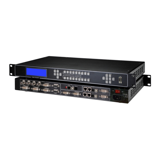
VSP 5162 – Quick Start
For full installation, configuration, and operation details, refer to the
NOTE
VSP 5162 user manual.
This guide provides quick start instructions for an experienced installer to set up
and operate the VSP 5162.
Installation and cabling features
Rear Panel
Connections
CVBS/SDI input (BNC)
2
1
CVBS input (BNC)
3 4
DVI input (DVI-I)
18
5
VGA input (DB15)
6 19
Mini switches
7
RJ-45 interface
8
USB control port
9
RS232 control port
10
LAN RJ-45 port, connect with
11
12
LED screen via CAT5 cable.
22 23
Step 1-Mounting
Turn off or disconnect all equipment power sources.
Step 2-CV/SDI input
CV/SDI input composite/3G signal from HD
player or HD camera.
(Auto detect composite signal or 3G SDI, 3G
SDI is optional module, VSP 5126 3G is VSP
5162 with 3G SDI module.)
Step 3-Composite input
Use to input composite signal
Supported standards: PAL,NTSC and SECAM
Step 4-DVI input
Use to input DVI from DVI player or
computer with DVI connector
Step 5-VGA input
Use to input VGA signal from VGA player
or computer with VGA connector
Step 6-DVI+VGA input
Use to input HDMI( from HD player), DVI or
VGA( from computer), YPbPr (from Satellite
Transmission or DVD)
Step 7 USB Input
Used to play media files from disk with
USB connect.
TX Card Power Connector
13 24
USB control port of TX card
14 25
TX Card DVI Input Connector
15
26
DVI+VGA input (DVI-I)
16
17
DVI output (DVI-I)
20
DVI+VGA output (DVI-I)
21
Power cord connector IEC-3
27
USB input port
28
NOTE
Signal connection:
1. Input HDMI signal via DVI to HDMI adapter.
2. Input VGA through to DVI to VGA adapter.
3. Input both DVI and VGA signal through DVI
to DVI + VGA adapter.
4. Input DVI, YPbPr or CV through DVI to DVI
+3 BNC adapter.
5. Or input DVI directly by DVI cable.
One side of DVI to DVI+VGA
adapter is DVI-I or DVI-D
male interface, another side
DVI-I or DVI-D female
interface.
One side of DVI to YPbPr
adapter is DVI-I male
interface, another side
YPbPr female interface.
One side of DVI to VGA
adapter is DVI-I male
interface, another side VGA
female interface.
Step 8-DVI+VGA output
Through DVI to VGA adapter,
VGA output to VGA monitor, DVI
ouput to DVI monitor or LED
control system
VSP 5162 Quick Start
Rev 1.0
Page 1 of 4
Advertisement
Table of Contents

Related Manuals for RGBlink VSP 5162


Summary of Contents for RGBlink VSP 5162
- Page 1 VSP 5162 – Quick Start For full installation, configuration, and operation details, refer to the NOTE VSP 5162 user manual. This guide provides quick start instructions for an experienced installer to set up and operate the VSP 5162. Installation and cabling features...
- Page 2 Step 13- Power pushing CUT or TAKE button. There are two different switch ways: Plug in power cord which has IEC connector, VSP 5162 CUT and TAKE: support AC power from 85 to 260 VAC,50-60Hz, which CUT is the direct switch without transiting effect means world wide compatible.
- Page 3 Choose Switch Effect such as fade-in-fade-out Step 6- Save mode loading from the list of Effect Mode. VSP 5162 supports 10 user saving modes, make sure all Switching time the saved parameters right, push LOAD button, and and speed are SVAE1~ SAVE10 buttons will light on, push anyone of also set here.
- Page 4 There are 10 user modes in Switch Mode, click on the button to load saved settings. VSP 5162 Quick Start Rev 1.0 Page 4 of 4...
Need help?
Do you have a question about the VSP 5162 and is the answer not in the manual?
Questions and answers