Table of Contents
Advertisement
Quick Links
Download this manual
See also:
User Manual
Advertisement
Table of Contents

Related Manuals for RGBlink VSP 168S


Summary of Contents for RGBlink VSP 168S
-
Page 1: User Manual
VSP 168S User Manual Manual #: RGB-RD-UM-V168S E001 Revision: V1.2 VSP 168S User Manual... - Page 2 Technology Co.,LTD. No part can be copied, reproduced or translated without permission. Notice RGBlink provides this manual ―as is‖ without warranty of any kind, no matter expressed or implied, including but not limited to the implied warranties or merchantability and fitness for a particular purpose. RGBlink may make improvements or changes to the products and the programs described in this publication at any time without notice.
- Page 3 30 days after the transfer of risks. In the event of justified notice of compliant, RGBlink can repair the fault or provide a replacement at its own discretion within an appropriate period. If this measure proves to be impossible or unsuccessful, the purchaser can demand a reduction in the purchase price or cancellation of the contract.
- Page 4 Company Address Xiamen RGBlink Science & Technology Co., Ltd. Headquarter: S603~604 Weiye Building Torch Hi-Tech Industrial Development Zone Xiamen, Fujian Province, P.R.C Shenzhen office: Floor 11, A1 Building, Baiwang R&D Building, Shahe West Road, Xili Town, Nanshan District, Shenzhen, Guangdong Province, P.R.C Beijing office: Room 602, Building 7, CaiManJie, No.67 Chaoyang...
-
Page 5: Power Source
To avoid fire hazard, use only the fuse having identical type, voltage rating, and current rating characteristics. Refer fuse replacement to qualified service personnel. Do Not Operate in Explosive Atmospheres To avoid explosion, do not operate this product in an explosive atmosphere. VSP 168S User Manual... - Page 6 Highlights an essential operating procedure, condition or statement. CAUTION The exclamation point within an equilateral triangle is intended to alert the user to the presence of important operating and maintenance (servicing) instructions in the literature accompanying the appliance. VSP 168S User Manual...
- Page 7 The table below lists the changes to the Video Processor User Manual. Format Time ECO# Description Principal V1.0 2014-03-11 0000# Release Vira V1.1 2014-06-04 0001# 1. Update the test pattern description Vira in ―Menu Orientation‖. V1.2 2014-09-25 0002# 1. Update the menu tree. Vira VSP 168S User Manual...
-
Page 8: Table Of Contents
System Overview ................24 Application Questions ................. 25 2. Hardware Orientation ..............26 In This Chapter ................. 26 VSP 168S Back Panel ..............27 CONT Interface ..................27 1. RS232 Interface ................... 27 2. USB Interface ..................27 INPUT Interface ..................27 3. - Page 9 14. DVI Output ..................29 15. DVI +VGA DVI Output ..............29 Switch and Power ..................29 16:Power ....................29 VSP 168S Front Panel ..............30 LCD Panel ....................31 Menu Keys ....................31 Signal Keys ....................31 Function Keys ................... 31 3.
- Page 10 Connection ....................56 Use ......................56 File Toolbar ....................56 Communication Toolbar ................59 Device Toolbar ..................59 Schedule Toolbar ..................60 Output Resolution Toolbar ..............61 Images Display Mode Toolbar..............62 Layout Toolbar ..................62 VSP 168S User Manual...
- Page 11 How to Realize Single Image Switching ........78 How to Set up the PIP ..............79 How to Set up the Size and Position of the Single Image ... 80 How to Set up Image Zoom ............81 VSP 168S User Manual...
- Page 12 Resolution is Insufficient ................. 91 Left Screen Appears Two Black Sides ........... 91 Adjust DE Deviation ................. 91 All Key Lights Light on Simultaneously .......... 92 Check If Dial Switch is Normal ............... 92 A. Specification ................93 VSP 168S User Manual...
- Page 13 B. Contact Information ..............95 C. Software Upgrade ..............96 VSP 168S User Manual...
-
Page 14: Brief Introduction
Brief Introduction This chapter is designed to introduce you to the VSP 168S User Manual. Areas to be covered are: Chapter Structure How to Use the Manual Terms and Definitions System Overview Application Questions VSP 168S... -
Page 15: Chapter Structure
1. Brief Introduction Chapter Structure Chapter Structure The following chapters provide instructions for all aspects of VSP 168S operations. Chapter 1 Brief Introduction Chapter 2 Hardware Orientation Chapter 3 Hardware Installation Chapter 4 Menu Orientation Chapter 5 Communication Software Guideline... -
Page 16: How To Use The Manual
For system setup and operations, refer to Chapter 6, ―System Setup and Operations‖ on page 72. Should you have any questions regarding the installation or operation of VSP 168S, please consult with the factory. Refer to Appendix B on page 95 for contact information. VSP 168S... -
Page 17: Term And Definitions
This allows the connector to lock into place without tools. “Brightness”: Usually refers to the amount or intensity of video light produced on a screen without regard to color. Sometimes called ―black level. VSP 168S User Manual... - Page 18 29 pins that handles both digital and analog video. “EDID”: Extended Display Identification Data – EDID is a data structure used to communicate video display information, including native VSP 168S User Manual...
- Page 19 The degree of compression can be adjusted, allowing a selectable tradeoff between storage size and image quality. JPEG typically achieves 10:1 compression with little perceptible loss in image quality. Produces blocking artifacts. VSP 168S User Manual...
- Page 20 “RJ-45”: Registered Jack-45. A connector similar to a telephone connector that holds up to eight wires used for connecting Ethernet devices. VSP 168S User Manual...
- Page 21 This includes film as well as video and television standards. “S-Video”: A composite video signal separated into the luma (―Y‖ is for luma, or black and white information; brightness) and the chroma (―C‖ is an abbreviation for chroma, or color information). VSP 168S User Manual...
- Page 22 8514/A card (35.5 kHz, 86 Hz) in mode 4. It has a pixel by line resolution of 640×480 with a color palette of 16 bits and 256,000 colors. “YCrCb”: Used to describe the color space for interlaced component video. VSP 168S User Manual...
- Page 23 1. Brief Introduction Terms and Definitions “YPbPr”: Used to describe the color space for progressive-scan (non-interlaced) component video. VSP 168S User Manual...
-
Page 24: System Overview
LED display application market. There are two kinds of rack mount structures available as option. One is 1 unit for two VSP 168S to be installed, and another is 2 unit size for up to 4 pieces VSP 168S. -
Page 25: Application Questions
1. Brief Introduction Application Questions Application Questions RGBlink offers solutions to demand technical problems. Any application questions, or required further information, please contact with our Customer Support Engineers. Refer to Appendix B for contact details. VSP 168S User Manual... -
Page 26: Hardware Orientation
Hardware Orientation In This Chapter This chapter provides detailed information about the VSP 168S hardware. The following topics are discussed: VSP 168S Back Panel VSP 168S Front Panel VSP 168S User Manual... -
Page 27: Vsp 168S Back Panel
2. Hardware Orientation VSP 168S Back Panel VSP 168S Back Panel The figure below illustrates the professional interface and control signals of VSP 168S back panel. INTERFACE INTERFACE RS232 Interface CVBS Input BNC port 2. 6 USB Interface VGA Input DB15 port... -
Page 28: 3. 3G-Sdi Input
SDI input, input video signal from HD camera and radio processing equipment, connect SDI interface via 75 ohms impedance BNC port. 4. SDI Loop Out SDI loop out. Connect to the SDI input of the next level VSP 168S or the device with SDI input. 10. CVBS Input CVBS input, input standard video signal from players, cameras etc.,... -
Page 29: Usb Control Port Of Sending Card
2. Hardware Orientation VSP 168S Back Panel Power has been already supplied by video processor, no external power supply needed. 6. USB Control Port of Sending Card 5. DVI Input Connect to the DVI outputs of video processors. (This connector does not support hot-plugging). -
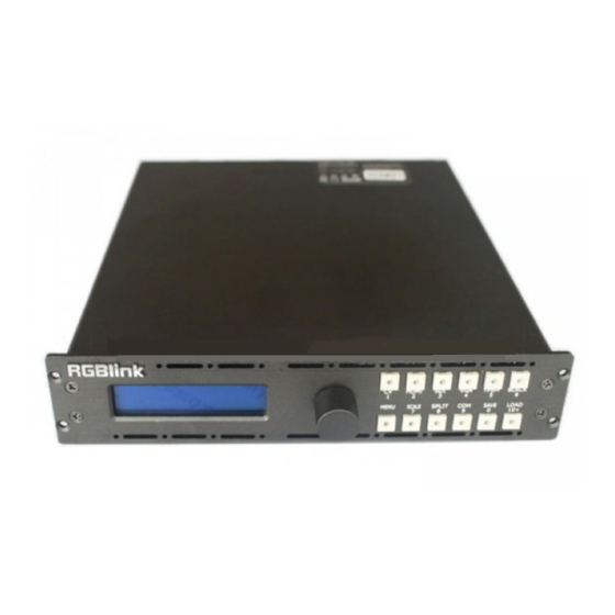
Page 30: Vsp 168S Front Panel
VSP 168S Front Panel VSP 168S Front Panel Insert the power cord, LCD module on the front panel will show RGBlink and go into self verification before it load last setting and send processed image to the target monitor. For the first setup, CV1 input is default source. -
Page 31: Lcd Panel
2. Hardware Orientation VSP 168S Front Panel VSP 168S front panel is as following: LCD Panel Used to show button menu and menus for interactive communication. Menu Keys Used to adjust LCD menu and information interaction and with the same function with enter to confirm current options. - Page 32 2. Hardware Orientation VSP 168S Front Panel disable the black function. Menu button: push MENU button to enter the menu items. Turn the knob to to select the relevant submenu. For details, please refer to MENU in menu orientation. Scale button: Push the button to scale the image. Turn the knob, user can change the size and position of the image.
-
Page 33: Hardware Installation
Hardware Installation In This Chapter This chapter provides comprehensive installation instruction for VSP 168S hardware: Following is the size of VSP 168S for your reference. VSP 168S User Manual... -
Page 34: Safety Precautions
Unpacking and Inspection Before opening VSP 168S process shipping box, inspect it for damage. If you find any damage, notify the shipping carrier immediately for all claims adjustments. As you open the box, compare its contents against the packing slip. -
Page 35: Menu Orientation
Menu Orientation In This Chapter This chapter describes all VSP 168S processor menus, including how they are accessed, the functions that are available, and descriptions of each menu tree (in block diagram format). The following topics are discussed: • MENU ... -
Page 36: Menu
Push MENU button to enter to menu items, menu shown as follows. Turn the knob to select menu item. After the menu means it’s in selected state. Turn the knob to enter corresponding for setting or view the menu. VSP 168S User Manual... - Page 37 4. MENU Orientation MENU VSP 168S User Manual...
-
Page 38: Input
Select <INPUT>, push the knob to confirm, show level 2 menus as follows: INPUT DETAIL: Display input signal information, including CV, HDMI, SDI, VGA, YPbPr. ZOOM ADJUST: It can adjust the image zoom size and positions, settings including as follows: VSP 168S User Manual... - Page 39 VGA input shiftment. ADC AUTO ADJUST: Auto adjusting for BRIGHTNESS. SDI ADJUST: When SDI input signal image shift, please adjust image’s H POS and V POS to display in full screen image. Sub menu as follows: VSP 168S User Manual...
-
Page 40: Output
1280×768×60, 1280×800×60, 1280×1024×60, 1360×768×60, 1366×768×60, 1400×1050×60, 1440×800×60, 1440×900×60, 1600×1200×60, 1680×1050×60, 1920×1080×50, 1920×1080×60, 1920×1120×60, 1920×1200×60, 2048×1152×60, 2560×812×60, 2560×816×60. CUSTOM: The special display project or LED display application would like to require special resolution settings to meet the requirement. VSP 168S User Manual... - Page 41 RESET: If image quality distorts by improper operation, it can be recover by reset. Note Only comments to professional operator. SCALE: It can adjust the image scale size and image position settings including as follows: H SIZE: Width setting. VSP 168S User Manual...
- Page 42 Normal: Original video proportion, 4:3 aspect ratios; 16:9 aspect ratios. PICTURE: Picture setting, including sub-menu as follows: BRIGHTNESS: It can change the image color BRIGHTNESS via BRIGHTNESS Settings. CONTRAST: It can change the image color CONTRAST via CONTRAST Settings. VSP 168S User Manual...
- Page 43 PBP T+B SWAP IMAGE: It can set PIP to swap exchange, when choose ON, it can switch IMAGE A and IMAGE B. ALPHA: Use can set the image transparency, the regulating range is among 0 to 16. VSP 168S User Manual...
- Page 44 Mode 2: Graphic content is controlled by double-picture transparency, the background is completely transparent. BLEND LEVEL: Can set the image display transparency, regulating range between 0~16. ABOVE/BELOW: ABOVE: In image 2, if the pixel value is higher than the setting value, then VSP 168S User Manual...
- Page 45 TEST PATTERN: Test pattern setting, turn the knob, there are 1 to 66 kinds of modes for choose. Notice: When the input comes from DVI, VGA, or SDI (input format is progressive only), the TEST PATTERN function will be enable and ready to operate. VSP 168S User Manual...
-
Page 46: Transition
2 menu as following: MODE: Switch mode, including the following modes: CUT: Seamless switching. FADE: Fade in fade out effect switching. POP L+T: PUSH L+T: POP R+T: PUSH R+T: POP L+B: PUSH L+B: POP R+B: PUSH R+B: VSP 168S User Manual... - Page 47 FADE TIME: Switch time setting. Turn the knob to choose the time and push the knob to confirm. The switching time ranges from 0 to1.0. VSP 168S User Manual...
-
Page 48: Split
DELAY CALL: Set delay the output time. When more than one equipment power on, and the processor is the end equipment in order to improve question that can’t identify the input signal and phenomenon that LED VSP 168S User Manual... -
Page 49: System
SYSTEM INFO: System information, including: MCU VER: Information of MCU version. VIDEO VER: Information of VIDEO version. SN: Serial number of VSP 168S. TECH SUPPORT: Including sales hotline, after-sale service, web site, email and telephone. DATE&TIME: Display date or time, including the following items: DATE: Display date. -
Page 50: Language
FACTORY RESET Enter FACTORY RESET to reset the IP, choose YES and push the SEL button to confirm, then VSP 168S is reset to its factory settings. After 5 seconds, it completes factory settings and is ready for more operations. -
Page 51: Communication Software Guideline
Communication Software Guideline In This Chapter This chapter provides detailed information about the control communication software. The following topics are discussed: Software Installation Software Operation How to Connect Windows Control Program by RS232 Interface VSP 168S User Manual... -
Page 52: Software Installation
5. Communication Software Guideline Software Installation Software Installation VSP 168S video processor is very easy to be configured with user friendly communication software, support drag and drop operation for edit and display. Also it can be customized with schedule function. - Page 53 5. Communication Software Guideline Software Installation User can select ―Change‖ to choose the VSP 168S install software: VSP 168S User Manual...
- Page 54 5. Communication Software Guideline Software Installation Click ―Next‖ to go on: Click ―Next‖ to go on: VSP 168S User Manual...
- Page 55 5. Communication Software Guideline Software Installation Click ―Next‖ to go on: Click ―Finish‖ and ready to run VSP 168S console: VSP 168S User Manual...
-
Page 56: Software Operation
VSP 168S communication software interface as shown: Connection Besides the power cord, the product default equip with the RS-232 line, DB9F line, and RJ11 (6 B4C) line to connect VSP 168S to the windows control program. For more detailed information, please refer to: ―How to Connect Windows... - Page 57 : Save script. Save current user parameters as script to the prescribed path. : Import template. There are six templates for user. Users can setup one of templates as the common one. : Export template. Export current config as template. VSP 168S User Manual...
- Page 58 User can click to choose which script user want to open. If user choose execute schedule when start, the next dialogue will display when software run. : Language, the software supports Chinese, English and German version. VSP 168S User Manual...
-
Page 59: Communication Toolbar
Communication Toolbar : Open COM. : Close COM. : Set COM. Device Toolbar : Synchronization. : Save to flash. Note Same as MENU SAVE SETUP SAVE TO or the same as SAVE key. : Load form Flash. VSP 168S User Manual... -
Page 60: Schedule Toolbar
FROM or the same as LOAD key. : Factory setup. : Advance. Note Advance is only done by engineer. Please connect us for password. : VGA adjustment. Note Same as MENU INPUT ADJUST. Schedule Toolbar : Customize schedule. VSP 168S User Manual... -
Page 61: Output Resolution Toolbar
Software Operation : Execute schedule. Execute tasks according to schedule. Output Resolution Toolbar User can choose different output resolution by selecting from pull down list. VSP 168S has 22 kinds of output resolutions for users selection. VSP 168S User Manual... -
Page 62: Images Display Mode Toolbar
If in single channel mode, the dialog is in grey and it is in limited use. If in dual channel mode, user can set the device to work in PIP or PBP mode directly with quick preset layout button as following. Note Same as MENU OUTPUT LAYOUT. VSP 168S User Manual... -
Page 63: Aspect Ratio Toolbar
Screen Parameter Toolbar User can set size and position of the screen simply, mainly applies to LED display users. After setting screen parameter, the user choice PIP or PBP operation, display picture can directly shows on corresponding screen. VSP 168S User Manual... -
Page 64: Image Toolbar
Freeze Frame, the video stop playing. Note Same as MENU OUTPUT DISPLAY MODE MODE. Use can set the volume or set mute mode. Note VSP 168S V1.3 can not support this function. VSP 168S User Manual... -
Page 65: Output Image Setup Toolbar
(images) in this area. This process is sync to the parameters in images toolbars. User Mode Toolbar Users can recall the saved user mode1, mode2 or mode3. Log Toolbar User can save or delete the operate log file. VSP 168S User Manual... -
Page 66: Information Toolbar
5. Communication Software Guideline Software Operation Information Toolbar It is the VSP 168S software version, core board version, firmware version and the serial number in bottom of the software interface. [Video Processor] Options Split: Split function, choose ―ON‖ can set H total, V total, H position, V position, H size and V size. - Page 67 Through the layout of the user can set the double-picture modes. Device Schedule: Users can set up VSP 168S to play the appointed input video automatically in time and operation of single or dual channels, ratio place. Users can setup up to 10 timing operation in the schedule.
-
Page 68: [Help] Options
5. Communication Software Guideline Software Operation USB Upgrade: Test Pattern: [Help] Options Version History: The update version of software. About: The information of the software version and the company. VSP 168S User Manual... -
Page 69: How To Connect Windows Control Program Rs232 Interface
Take out the RS 232 cable as following (RS-232, with 9-pin on one end, RJ11 on the other side). Connect one side of the RJ11 download line to the RS232 on the video processor VSP 168S, and the other side to be connected to the serial port on the PC. - Page 70 Click [Device Manager] ―+‖ on the left, check the COM number, as following, COM1 is offered. Remember the COM be used and then run the control software, find [Communication] option. In default, first time user have to click button, as following: VSP 168S User Manual...
- Page 71 5. Communication Software Guideline How to Connect Windows Control Program by RS232 Interface Check and tap [Serial], Serial Port, for example, is COM6 which is checked from device manager. Set VSP 168S Boud Rate to be :115200, Click[Confirm] after setting. Click...
-
Page 72: System Setup And Operations
How to Use Black Out How to Realize the Text Overlay Setting How to Realize the Freeze and the Live Image Switching How to Save the Parameter How to Load the Saved Parameter VSP 168S User Manual... -
Page 73: Interface And Input Signal Option
8. 9 10/100M Interface RJ45 Power 14. DVI1 have default the main image output , use for connecting the sending card of LED display, VSP 168S supports resolution format as following: 800×600×60, 1024×768×60, 1024×768×75, 1280×720×50, 1280×720×60, 1280×768×60, 1280×800×60, 1280×1024×60, 1360×768×60, 1366×768×60, 1400×1050×60, 1440×800×60, 1440×900×60,... - Page 74 11. VGA (DB15 Port)Can support HD player, computer, video signal. Through the DB15 interface input signal. 12. HDMI Input the video signal from HD player, DVD, computer, set top box and hard disk, etc. 16. Power : Power has been already supplied for video processor. VSP 168S User Manual...
-
Page 75: How To Confirm The Device Is In Normal Operation
3. After scanning, the device is in start state, the LCD module show as follows: RGBLINK 视诚科技 亮彩系列 AVDSP SERIES VSP168 WAIT INIT DEVICE… INPUT:CV1 NO INPUT 4. After start, the equipment is default load SAVE1 parameter, CV1 key light is on, and the device is in normal working. VSP 168S User Manual... -
Page 76: How To Do Customized Output Resolution
@ is the refresh rate. Only digital 50 or digital 60 supports for the refresh rate. Use the digital buttons to finish the settings, . For example to input refresh rate 60. CUSTOM >1536×1536@60 VSP 168S User Manual... - Page 77 6. System Setup and Operation How to Do Customized Output Resolution After input all the values, push knob to enable VSP 168S to output this resolution. VSP 168S will take 5 to 10 seconds to enable this output resolution. Note All the resolution inside the value 2048 x 1152 x 60 = 141557760 can support.
-
Page 78: How To Realize Single Image Switching
CV1 button light turns off after pushing VGA button. VGA button light is on if the VGA signal is effective and stable. And if the VGA signal is invalid or no input, DVI button light will flash. VSP 168S User Manual... -
Page 79: How To Set Up The Pip
IMAGE A and IMAGE B exchange. ALPHA: Can set the image transparency, the regulating range is among 0 to 16. SELECT: Can choose to set the size or position of IMAGE A or IMAGE B Individually. VSP 168S User Manual... -
Page 80: How To Set Up The Size And Position Of The Single Image
>H SIZE 1920 V SIZE 1080 >H POS V POS 5. If image quality distorts by improper operation, it can be recover by reset. >RESET VSP 168S User Manual... -
Page 81: How To Set Up Image Zoom
H LIFT/RIGHT--Zoom in horizontal but in both left and right direction from its middle. CENTER--Zoom in 4 corner direction from center. RESET--If image quality distorts by improper operation, it can be recover by reset. VSP 168S User Manual... -
Page 82: How To Realize The Screen Size And Full Size Switching
How to Realize the Screen Size Setting How to Realize the Screen Size Setting VSP 168S supports the screen parameters to meet the requirement where user want to switch between scale screen size and full display size (like monitor). This is only enable for a single display window. Following is an example of a screen size is1408 x 832. -
Page 83: How To Use Black Out
Black out description: Black signal realizes one-key-touch to a black screen. VSP 168S black provides effect processing when output, Black switching with fade in fade out effect. The operation is as below: Push [BLACK] button, and the output turns to BLACK screen with fade in fade out effect. -
Page 84: How To Realize The Text Overlay Setting
Mode 2: Graphic content is controlled by double-picture transparency, the background is completely transparent. Turn the knob and choose the mode. 5. Push the [MENU] button, return to <TEXT OVERLAY>, turn the knob, choose ABOVE/BELOW to select the layer position for IMAGE B. VSP 168S User Manual... - Page 85 BLUE: The value range of color BLUE that to be set, regulating range between 0~255. 8. At the same time, user can view the effect through the screen, to get a better setting. Note: All the above settings are available only for IMAGE B. VSP 168S User Manual...
-
Page 86: How To Realize The Freeze And Live Image Switching
4. Turn the knob again, choose LIVE, the current freeze image is switched to live image. LIVE >MODE >> Note In PIP mode, the Image A and Image B can be frozen or live at the same time. VSP 168S User Manual... -
Page 87: How To Save The Parameter
How to Save the Parameter Save user mode to the customer for different scene directly call. Leave out the edit operation inconvenience, VSP 168S provides ten save parameters. 1. Push the [SAVE] button, and start the SAVE function. 2. Turn the knob, select the location that need to save, for example, save to SAVE2, choose SAVE2 and confirm, and save the parameter finished. -
Page 88: How To Load The Saved Parameter
How to Load the Saved Parameter Save user mode is for user for different scene directly call. Leave out the edit operation inconvenience, VSP 168S provides ten save parameters. 1. Push the [LOAD] button, and start the LOAD function. 2. Turn the knob, select the location that need to load, for example, load from SAVE1, choose SAVE1 and confirm, and load the parameter finished. -
Page 89: Common Questions And Solutions
Flash Point in LED Display Output LED Display only Displays Part of the Image No Display in the Second Half Part of LED Display Left Screen Appears Two Black Sides All Key Lights Light on Simultaneously VSP 168S User Manual... -
Page 90: No Output In Led Display
If display normally shows and no flash point, please check whether DVI outlets put tight. If display flashes point, please judge if input signal, wire, and interface are normal. VSP 168S User Manual... -
Page 91: Led Display Only Displays Part Of The Image
<OUTPUT> and find the corresponding output name, such as "DVI1 OUT ADJUST", and find "DVI1 DE" again, make an adjustment for corresponding horizontal and vertical DE, please remember to save to the corresponding channel after setting up, save to SAVE1 by default. VSP 168S User Manual... -
Page 92: All Key Lights Light On Simultaneously
All Key Lights Light on Simultaneously Check If Dial Switch is Normal Shut the power, check if red dial switch near CV are upward. Reboot if it faces down, and reboot. The function of the red dial switched is mainly upgrade. VSP 168S User Manual... -
Page 93: Specification
Format Standard HDMI 1.3 3G-SDI Input Number of Inputs Connector BNC interface Transmission speed 19.4Mbps~1.5Gbps ITU-R BT.656,ITU-R BT.601,SMPTE 259M, SMPTE 292, Supported Standard SMPTE 297 Belden 1694A 100m self-adaptive 3G,200m Balance self-adaptive 1.485G,350m self-adaptive 270Mbps SDI output VSP 168S User Manual... - Page 94 Support PIP、PBP for any two inputs Extras Communication RS232 USB TCP/IP Power Supply 85-264V 2.1A IEC-3 Working Environment 0° C~45° C Stored Environment 10% to 90% Product Warranty 3 years parts and labor warranty VSP 168S User Manual...
- Page 95 All video products are designed and tested to the highest quality standard and backed by a full 3 years parts and labor warranty. Warranties are effective upon delivery date to customer and are non-transferable. RGBlink warranties are only valid to the original purchase/owner. Warranty related...
- Page 96 2. CORE Panel Upgrade Upgrade by copy the file, the name of the file is: VIDEO.fvb, and upgrade steps are as follows: (1) Connect the USB interface of VSP168_V1.3 to the computer with a USB cable. VSP 168S User Manual...
- Page 97 (5) Reboot the device, and enter the menu to check if the version is right, factory reset is completed. Operation steps are: MENUSYSTEMSYSTEM INFOMCU VER. VSP 168S User Manual...
Need help?
Do you have a question about the VSP 168S and is the answer not in the manual?
Questions and answers