
Related Manuals for RGBlink VSP 198CVS


Summary of Contents for RGBlink VSP 198CVS
-
Page 1: User Manual
VSP 198CVS User Manual Manual #: RGB-RD-UM-V198CVS E001 Revision: V1.1 This User Manual Applies to VSP 198CV and VSP 198CVS! VSP 198CVS User Manual... - Page 2 No part may be copied, reproduced or translated without permission. Notice RGBlink provides this manual ―as is‖ without warranty of any kind, either expressed or implied, including but not limited to the implied warranties or merchantability and fitness for a particular purpose. RGBlink may make improvements and/or changes to the product(s) and/or the program(s) described in this publication at any time without notice.
- Page 3 30 days after the transfer of risks. In the event of justified notice of compliant, RGBlink can repair the fault or provide a replacement at its own discretion within an appropriate period.
- Page 4 Company Address Xiamen RGBlink Science & Technology Co., Ltd. Headquarter: S603~604 Weiye Building Torch Hi-Tech Industrial Development Zone Xiamen, Fujian Province, P.R.C Shenzhen office: Floor 11, A1 Building, Baiwang R&D Building, Shahe West Road, Xili Town, Nanshan District, Shenzhen, Guangdong Province, P.R.C...
-
Page 5: Power Source
Use the Proper Fuse To avoid fire hazard, use only the fuse having identical type, voltage rating, and current rating characteristics. Refer fuse replacement to qualified service personnel. Do Not Operate in Explosive Atmospheres VSP 198CVS User Manual... - Page 6 Highlights an essential operating procedure, condition or statement. CAUTION The exclamation point within an equilateral triangle is intended to alert the user to the presence of important operating and maintenance (servicing) instructions in the literature accompanying the appliance. VSP 198CVS User Manual...
- Page 7 Change History The table below lists the changes to the Video Processor User Manual. Format Time ECO# Description Principal V1.0 2013-09-22 0000# Release Peter V1.1 2014-07-11 0001# 1. Update the Menu. Vira 2. Add ―USB Update‖. VSP 198CVS User Manual...
-
Page 8: Table Of Contents
System Overview ..................23 Application Questions .................. 24 2. Hardware Orientation ..............25 In This Chapter .................... 25 VSP 198CVS Back Panel ................26 CONT Interface ...................... 26 7: Dial Switch ......................26 8. 10/100M UDP Interface ..................26 9. USB Interface ....................26 10. - Page 9 18:VGA Output ....................28 11.19:Sending Card interface ................28 Switch and Power ....................28 12.20:Power Interface and Switch ..............28 VSP 198CVS Front Panel ................29 OLED Panel ......................30 Menu Button ......................30 Signal Buttons ....................... 30 Function ........................ 31 3.
- Page 10 SPLIT FUNCTION ..................53 SCALE FUNCTION ..................54 5. Communication Software Guideline ..........55 In This Chapter .................... 55 Software Installation ..................56 Software Operation ..................60 Connection ......................60 Use ........................63 File Toolbar ......................63 VSP 198CVS User Manual...
- Page 11 How to Connect Window Control Program by RS232 Interface ....76 How to Connect Windows Control Program by USB Interface ..... 79 How to Connect Windows Control Program by LAN Interface ..... 83 6. System Setup and Operations ............86 In This Chapter .................... 86 VSP 198CVS User Manual...
- Page 12 7. Common Questions and Solution ..........112 In This Chapter ..................112 No Output in Large Screen ................. 113 Confirm if there are any input singles ..............113 Confirm if signal output ..................113 Large Screen Output Flash Point ..............113 VSP 198CVS User Manual...
- Page 13 Left of the Screen Appears Two Black Sides ..........114 Adjust DE deviation ..................... 114 All Key Lights Light Simultaneously ............115 Check if dial switches are normal ............... 115 A. Specification ................. 116 B. Contact Information ..............119 C. Software Upgrade ................. 120 VSP 198CVS User Manual...
-
Page 14: Introduction
Introduction This chapter is designed to introduce you to the VSP 198CVS User Manual. Areas to be covered are: Chapter Structure How to Use This Manual Terms and Definitions System Overview Application Questions VSP 198CVS... -
Page 15: Chapter Structure
1. Introduction Chapter Structure Chapter Structure The following chapters provide instructions for all aspects of VSP 198CVS operations. Chapter 1 Introduction Chapter 2 Hardware Orientation Chapter 3 Hardware Installation Chapter 4 Menu Orientation Chapter 5 Communication Software Guideline Chapter 6... -
Page 16: How To Use This Manual
For system setup and operations, refer to Chapter 6, ―System Setup and Operations‖ on page 86. Should you have any questions regarding the installation or operation of VSP 198CVS, please consult with the factory. Refer to Appendix B, ―Contact information‖ on page 119. VSP 198CVS... -
Page 17: Terms And Definitions
Telecommunications Wiring Standard. “Color bars”: A standard test pattern of several basic colors (white, yellow, cyan, green, magenta, red, blue, and black) as a reference for system alignment and testing. In NTSC video, the most commonly VSP 198CVS User Manual... - Page 18 “Frame”: In interlaced video, a frame is one complete image. A video frame is made up of two fields, or two sets of interlaced lines. In a film, a frame is one still image of a series that makes up a motion image. VSP 198CVS User Manual...
- Page 19 This alternation helps cancel out phase errors. For this reason, the hue control is not needed on a PAL TV set. PAL, in many transmission forms, is widely used in Western Europe, Australia, VSP 198CVS User Manual...
- Page 20 This is a 10-bit, scrambled, polarity independent interface with common scrambling for both component ITU-R 601 and composite digital video and four channels of (embedded) digital audio. “Seamless Switching”: A feature found on many video switchers. This VSP 198CVS User Manual...
- Page 21 31.5 kHz and vertical frequency of 70 Hz (Mode 1, 2) and 60 Hz (Mode 3). The signal is non-interlaced in modes 1, 2, and 3 and interlaced when using the 8514/A card (35.5 kHz, 86 Hz) in mode 4. It VSP 198CVS User Manual...
- Page 22 640×480 with a color palette of 16 bits and 256,000 colors. “YCrCb”: Used to describe the color space for interlaced component video. “YPbPr”: Used to describe the color space for progressive-scan (non-interlaced) component video. VSP 198CVS User Manual...
-
Page 23: System Overview
1. Introduction System Overview System Overview The VSP 198CVS is a multiple outputs video processor that accepts a wide variety of video signals, including RGB computer graphic by DVI, VGA video, standard and HDTV video by HDM. Composite, SDI (SD/HD/3G Compatible), DVI and SDI supports loop through output for cascade or preview. -
Page 24: Application Questions
1. Introduction Application Question Application Questions RGBlink offers solutions to demanding technical problems. Any application questions, or required further information, please contact with our Customer Support Engineers. Refer to Appendix B for contact details. VSP 198CVS User Manual... -
Page 25: Hardware Orientation
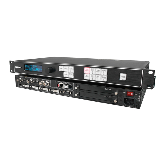
Hardware Orientation In This Chapter This chapter provides detailed information about the VSP 198CVS hardware. The following topics are discussed: VSP 198CVS Back Panel VSP 198CVS Front Panel VSP 198CVS User Manual... -
Page 26: Vsp 198Cvs Back Panel
2. Hardware Orientation VSP 198CVS Back Panel VSP 198CVS Back Panel The figure below illustrates the professional interface and control signals of VSP 198CVS back panel. INTERFACE INTERFACE CVBS Input 11.19 Sending card interface VGA Input Power Switch SDI Input... -
Page 27: 10. Rs232 Interface
5 via 75 ohms impedance BNC port. Note 5 and 6 input interface is S option module . 6:SDI Loop Out SDI loop output, connect the SDI input of the next VSP 198CVS for VSP 198CVS User Manual... -
Page 28: 13:Hdmi Input
DVI input, input the video signal from computer, DVI signal generator. Can be compatible with HDMI 1.3. (This connection can not support hot-plugging). 15:DVI Loop Out DVI loop out, connect to the DVI input of the next level VSP 198CVS or the device with DVI input. OUTPUT Interface 16.17:DVI Output DVI output, connect to the monitor or LED screen which has DVI interface (This DVI connector can not support hot-plugging). -
Page 29: Vsp 198Cvs Front Panel
Plug in the power cord and push power to ON position. OLED module on the front panel will show RGBlink and go into its self verification before it load last setting config and send processed image to the target monitor. -
Page 30: Oled Panel
2. Hardware Orientation VSP 198CVS Front Panel VSP 198CVS front panel as following: OLED Panel Used to show button menu and menus for interactive communication; Menu Button Used to adjust menu on OLED and for information interaction. Push the rotary button to confirm current options. -
Page 31: Function
2. Hardware Orientation VSP 198CVS Front Panel DVI input selection button, its LED light turns on, output will be switched to this channel. HDMI input selection button, its LED light turns on, output will be switched to HDMI this channel. - Page 32 2. Hardware Orientation VSP 198CVS Front Panel Split function button: push the button, its LED light turns on, split function is SPLIT open. OLED menu shows as follows: —>SPLIT Turn knob, choose SPLIT, and choose ON, OLED menu shows as follows: —>SPLIT...
- Page 33 2. Hardware Orientation VSP 198CVS Front Panel LOAD button: push it to enter LOAD mode, turn the knob or push the LOAD number button which light up to load the saved parameters. Currently, it supports 10 loading modes from 1, 2, 3, 4, 5, 6, 7, 8, 9, 0, which means LOAD user mode 1~10.
-
Page 34: Hardware Installation
Hardware Installation In This Chapter This chapter provides comprehensive installation instruction for VSP 198CVS hardware: Following is the mechanic info of VSP 198CVS for your reference. VSP 198CVS User Manual... -
Page 35: Safety Precautions
If there is damage, notify the shipping carrier immediately for all claims adjustments. Site Preparation The environment in which you install your VSP 198CVS should be clean, properly lit, free from static, and have adequate power, ventilation, and space for all components. -
Page 36: Menu Orientation
Menu Orientation In This Chapter This chapter describes all VSP 198CVS processor menus, including how they are accessed, the functions that are available, and descriptions of each menu tree (in block diagram format). The following topics are discussed: • MENU ... -
Page 37: Menu
Push the MENU to menu items, menu as shown: Turn knob buttons to select menu items. > before the menu means it’s in selected state. Push the knob to enter corresponding setting or view the menu. VSP 198CVS User Manual... -
Page 38: Output Format
Users can choose different output formats by turning the knob, this option includes 22 common standard output resolutions, shown as follows: 800×600×60, 1024×768×60, 1024×768×75, 1280×720×50, 1280×720×60, 1280×768×60, 1280×800×60, 1280×1024×60, 1360×768×60, VSP 198CVS User Manual... -
Page 39: Screen Parameters
How to Realize the Screen Size and Full Size Switching. PICTURE Push the [MENU] button to go into the menu items, turn the knob button to select <PICTURE>, show menus as follows: >> —>ZOOM SCALE >> VSP 198CVS User Manual... - Page 40 RESET: If image quality distorts by improper operation, it can be recover by factory reset. NOTE The SCALE button can also fulfill this setting. For details, please refer to the instructions in the manual: How to Set up the Size and Position of the Single Image. VSP 198CVS User Manual...
-
Page 41: Adjust
ADJUST Adjust menu including: Input signal sources adjust, Image quality settings, Output signal adjust. Menu including as follows: Input signal sources adjust : VGA1 SIGNAL TYPE: Program VGA1 button is VGA signal or YPbPr signal. VSP 198CVS User Manual... - Page 42 ANTI-ALIAS: If there is sawtooth when input SDI signal, user can do anti-alias processing by modify STEP_1 to STEP_7, and different STEP with different effects. System default STEP_1. RESET: If image quality distorts by improper operation, it can be recover by factory reset. VSP 198CVS User Manual...
- Page 43 DE, as follows: H SIZE: Width setting. V SIZE: Height setting. H POS: Horizontal phase setting. V POS: Vertical phase setting. When the signal source of the screen appear black side, can use this VSP 198CVS User Manual...
-
Page 44: Text Overlay
RedOnBk2: Red On Black 2. RedOnWh1: Red On White 1. RedOnWh2: Red On White 2. BLEND MODE: Blend mode, with two modes, ―Mode 1‖ and ― Mode 2‖. Mode 1: Graphic content locate at the top and is non-transparent, VSP 198CVS User Manual... -
Page 45: System
0 ~ 248. For details, please refer to the instructions in the manual: How to Realize the Text Overlay Setting. SYSTEM It can adjust the system function settings including as follows: VSP 198CVS User Manual... - Page 46 OUTPUT DETAIL:Show the output signal information. SYSTEM INFO: System information. COM. VERSION: Information of COM version. FIRMWARE VERSION: Information of firmware version. SN: Serial number of VSP 198CVS. IP: IP address. DATE&TIME: Show or change the date or time. VSP 198CVS...
-
Page 47: Language
MENU and SEL buttons together to release lock model!" User can push the two buttons together to unlock the equipment. FACTORY RESET Enter FACTORY RESET to reset the IP, choose YES and push the knob to VSP 198CVS User Manual... - Page 48 4. Menu Orientation MENU confirm, then VSP 198CVS is reset to its factory settings. After 5 seconds, it completes factory settings and is ready for more operations. VSP 198CVS User Manual...
-
Page 49: Quick Menu
OFF: No deinterlace, with effect switching. IMAGE ENHANCE: Image enhancement function, used for image edge sharpening, color reduction and image scaling. MODE: Special effects switching mode. DISSOLVE: Fade in fade out effects switching. CUT: Fast switching. VSP 198CVS User Manual... - Page 50 WIPE TOP RIGHT IN: WIPE TOP RIGHT OUT: WIPE BOTTOM LEFT IN: WIPE BOTTOM LEFT OUT: WIPE BOTTOM RIGHT IN: WIPE BOTTOM LEFT OUT: WIPE LEFT IN: WIPE LEFT OUT: WIPE RIGHT IN: WIPE RIGHT OUT: VSP 198CVS User Manual...
-
Page 51: Save Function
—>SAVE 1 Button is on can be saved Button flashes will be overwrite According to the OLED module information to save operation. For details please refer to the instructions in the manual: How to Save the Parameter. VSP 198CVS User Manual... -
Page 52: Load Function
LAYOUT: There are 7 PIP layouts, Can choose PIP layouts anyone, the corresponding results are as follows. PIP L+T PBP L+R PBP T+B SELECT: Can choose to set the size or position of IMAGE A or IMAGE B individually. VSP 198CVS User Manual... -
Page 53: Split Function
H TOTAL 1080 H POS —>V POS H SIZE 1920 V SIZE 1080 RESET H TOTAL: Horizontal total. V TOTAL: Vertical total. H POS: Horizontal phase setting. V POS: Vertical phase setting. H SIZE: Width setting. VSP 198CVS User Manual... -
Page 54: Scale Function
RESET: If image quality distorts by improper operation, it can be recover by factory reset. For details, please refer to the instructions in the manual: How to Set up the Size and Position of the Single Image. VSP 198CVS User Manual... -
Page 55: Communication Software Guideline
The following topics are discussed: Software Installation Software Operation How to Connect Windows Control Program by RS232 Interface How to Connect Windows Control Program by USB Interface How to Connect Windows Control Program LAN Interface VSP 198CVS User Manual... -
Page 56: Software Installation
5. Communication Software Guideline Software Installation Software Installation VSP 198CVS video processor is very easy to be configured with user friendly communication software, support drag and drop operation for edit and display. Also it can be customized with schedule function. - Page 57 5. Communication Software Guideline Software Installation User can select ―Change‖ to choose the VSP 198CVS install software: VSP 198CVS User Manual...
- Page 58 5. Communication Software Guideline Software Installation Click ―Next‖ to go on: Click ―Next‖ to go on: VSP 198CVS User Manual...
- Page 59 5. Communication Software Guideline Software Installation Click ―Next‖ to go on: Click ―Finish‖ and ready to run VSP 198CVS console: VSP 198CVS User Manual...
-
Page 60: Software Operation
5. Communication Software Guideline Software Operation Software Operation Install communication which comes with the package of VSP 198CVS device. Double click icon from home screen to run the software. Double click icon to run the software. VSP 198CVS communication software interface as shown:... - Page 61 Confirm used COM and open control software, click [communication] page, enter setup option, serial is the default COM, click icon refresh COM number, choose available COM, default Baud rate is115200. After serial setting, click icon, the icon becomes when VSP 198CVS User Manual...
- Page 62 ―How to Connect Windows Control Program by RS232 Interface‖. User can also connect the computer and VSP 198CVS with USB cable. For details, please refer to ―How to Connect Windows Control Program by USB Interface‖ . Ethernet , user can fill any number less than 1023 in local port, the remote port must be 192.168.0.100 and the remote port must be 1000.
-
Page 63: Use
: Open script. User can open saved script and alter its parameters. : Save script. Save current user parameters as script to the prescribed path. : Import template. There are six templates for user. Users can setup one of templates as the common one. VSP 198CVS User Manual... - Page 64 If user choose open device when start, user can use last run, use script file or none when user start. User can click to choose which script user want to open. If user choose execute schedule when start, the next dialogue will display when software run. VSP 198CVS User Manual...
-
Page 65: Communication Toolbar
5. Communication Software Guideline Software Operation : Language. The software supports Chinese, English and German version. Communication Toolbar : Open COM. : Close COM : Set COM. Device Toolbar : Synchronization. : Save to flash. VSP 198CVS User Manual... - Page 66 5. Communication Software Guideline Software Operation : Load form Flash. : Factory setup. : Advance. Note Advance is only done by engineer. Please connect us for password. Schedule Toolbar : Customize schedule. VSP 198CVS User Manual...
-
Page 67: Help Toolbar
5. Communication Software Guideline Software Operation : Execute schedule. Execute tasks according to schedule. Help Toolbar About: Display information of software; VSP 198CVS User Manual... -
Page 68: Output Resolution Toolbar
5. Communication Software Guideline Software Operation Output Resolution Toolbar User can choose different output resolution by selecting from pull down list. VSP 198CVS has 22 output resolutions for users selection. Note Same as MENU OUTPUT FORMAT Images Display Mode Toolbar Choose to work in single channel or dual channel. -
Page 69: Aspect Ratio Toolbar
VGA, green toolbar says it has chosen the current interface for channel 1 input interface, the default last single channel chosen interface for channel 2 input interface, the currently selected channel will be shown on the right side of the source. VSP 198CVS User Manual... -
Page 70: Screen Parameter Toolbar
Display toolbar Users can set Alpha value of ―dynamic Video‖ and ―static current frame‖ through display toolbar. When it is in dynamic Video, the video plays properly; when it is in static current frame, the video stop playing. VSP 198CVS User Manual... -
Page 71: Output Image Setup Toolbar
Gamma function. For further information, users can contact with our customer service team. Note Same as MENU ADJUST GAMMA Output Image Setup Toolbar User can customize the brightness and the contrast. Note Same as MENU IMAGE QUALTY VSP 198CVS User Manual... -
Page 72: Images Display Toolbar
Users can recall the saved user mode1, mode2 or mode3 Log Toolbar User can save or delete the operate log file. Information Toolbar It is the VSP 198CVS software version, core board version, firmware version and the serial number in bottom of the software interface. VSP 198CVS User Manual... -
Page 73: [Video Processor] Options
5. Communication Software Guideline Software Operation [Video Processor] Options Layout: Through the layout of the user can set a variety of double-image mode, single image mode is off. VSP 198CVS User Manual... - Page 74 5. Communication Software Guideline Software Operation Device Schedule: Users can set up VSP 198CVS to play the appointed input video automatically in time and operation of single or dual channels, ratio place. Users can setup up to 10 timing operation in the schedule.
- Page 75 5. Communication Software Guideline Software Operation Input Config: Define VGA1and VGA2 Input source types ,VGA input compatible with YPbPr. Note Same as MENU ADJUST 1/VGA2 SIGNAL TYPE VSP 198CVS User Manual...
-
Page 76: How To Connect Window Control Program By Rs232 Interface
Take out the RS 232 cable as following(RS-232, with 9-pin on one end, RJ 11 on the other side). Connect one side of the RJ11 download line to the RS232 on the video processor VSP 198CVS, and the other side to be connected to the serial port on the PC. - Page 77 Click [Device Manager] ―+‖ on the left, check the COM number, as following, COM1 is offered. Remember the COM you are using and then run the control software, find [Communication] option. In default, first time user have to click button, as following: VSP 198CVS User Manual...
- Page 78 5. Communication Software Guideline How to Connect Windows Control Program by RS232 Interface Check and tap [Serial], Serial Port , for example, is COM6 which is checked from device manager. Set VSP 198CVS Boud Rate to be :115200, Click [Confirm] after setting. Click [open serial], check if [COM] icon is on the bottom right corner,when there is the prompt green...
-
Page 79: How To Connect Windows Control Program By Usb Interface
Connect the USB cable to the PC and the video processor. Turn on the VSP 198CVS, for the first time to use USB, the PC will remind finding the new hardware and ask to install the driver for this new driver: Install from the list or specified location, press ―NEXT‖:... - Page 80 5. Communication Software Control Guide How to Connect Window Control Program by USB Interface When the installation finish, can go to check the installed COM port inside the device management, as following image shows: VSP 198CVS User Manual...
- Page 81 How to Connect Window Control Program by USB Interface Install the console software, and run after install, shows the interface of the console as following: Select the COM as installed just now, and set the VSP 198CVS Boud Rate to be: 115200. VSP 198CVS...
- Page 82 VSP 198CVS. VSP 198CVS User Manual...
-
Page 83: How To Connect Windows Control Program By Lan Interface
First, install the windows control software to the control computer; Connect VSP 198CVS and computer with cable, the connection diagram is as follow: Power on VSP 198CVS and start the network function, specific steps as below: The first step: push MENU button, login MENU—SYSTEM—ETHERNET,... - Page 84 If computer IP address and equipment IP address are not in same band, For example, the computer IP address is 218.032.010.201;We need to revise the computer IP address to 192.168.0.xxx. Open network connections, right click on properties, Select Internet protocol (TCP/IP),then VSP 198CVS User Manual...
- Page 85 Input equipment IP address, click [OK]. Click to open the serial port, if the [Comm] button (in the lower-right corner of the control software interface) is green, and log outputs information smoothly, then you would control the device through PC software. VSP 198CVS User Manual...
-
Page 86: System Setup And Operations
How to Realize Test Pattern Output and Settings How to Set up the Playlist How to Use Black Out How to Realize LAN Remote Control Settings How to Save the Parameter How to Load the Saved Parameter VSP 198CVS User Manual... -
Page 87: Interface And Input Signal Option
RJ11(RS232) control Interface 20 Power input interface 16. 17. DVI output, default the main image output, use for connecting the sending card of LED screen, VSP 198CVS support resolution format as following: 800x600x60Hz, 1024x768x60Hz, 1024x768x75Hz, 1280x720x60Hz, 1280x720x50Hz, 1280x768x60Hz, 1280x800x60Hz, 1280x1024x60Hz,... - Page 88 HDMI cable to connect the computer graphics HDMI output or DVD HDMI output. 3G SDI(BNC Port)Can receive video signal from HD player and radio processing equipment, connect interface 5 via 75 ohms BNC port. VSP 198CVS User Manual...
-
Page 89: User Guideline
The fourth step set up LED screen width size. The fifth step set up LED screen horizontal size. The sixth step set up LED screen Vertical size. The seventh step set up input source. The eighth step up save. VSP 198CVS User Manual... -
Page 90: How To Realize Single Image Switching
DVI button light will flash. The same method can switch the signals among CV2, VGA1, VGA2, DVI, HDMI, SDI. Note Only cut is supported among the switch of CV1, CV2, VGA2, HDMI and SDI. VSP 198CVS User Manual... -
Page 91: How To Set Up The Pip
ALPHA: Can set the image transparency, the regulating range is among 0 to 16. SELECT: Can choose to set the size or position of IMAGE A or IMAGE B individually. Note SPLIT Use function reuse key to select IMAGE A or IMAGE B. VSP 198CVS User Manual... -
Page 92: How To Set Up The Split
How to Set up the SPLIT How to Set up the SPLIT SPLIT is used when multiple VSP 198CVS are used in cascade mode. When do cascade, connect the signals to the signal distributor first, and then connect from the outputs of the signal distributor to each input of VSP 198CVS. - Page 93 6. System Setup and Operation How to Set up the SPLIT VSP 198CVS User Manual...
-
Page 94: How To Set Up The Size And Position Of The Single Image
H SIZE: Width setting. V SIZE: Height setting. H POS: Horizontal phase setting. V POS: Vertical phase setting. RESET: If image quality distorts by improper operation, it can be recover by factory reset. VSP 198CVS User Manual... -
Page 95: How To Do Customized Output Resolution
@ is the refresh rate. Only digital 50 or digital 60 supports for the refresh rate. Use the digital buttons to finish the settings, . For example to input refresh rate 60. VSP 198CVS User Manual... - Page 96 6. System Setup and Operation How to Do Customized Output Resolution CUSTOMIZED *1536×1536@60 After input all the values, push knob to enable VSP 198CVS to output this resolution. VSP 198CVS will take 5~10 seconds to enable this output resolution. Note All the resolution inside the value 2048 x 1152 x 60 = 141557760 can support.
-
Page 97: How To Realize The Screen Size And Full Size Switching
How to Realize the Screen Size and Full Size Switching VSP 198CVS supports the screen parameters to meet the requirement where user want to switch between scale screen size and full display size (like monitor). This is only enable for a single display window. Following is an example of a screen size is1408 x 832. -
Page 98: How To Set Up Image Zoom
H RIGHT--Zoom in horizontal and the image will be zoom in to the right direction from its left. H LIFT/RIGHT--Zoom in horizontal but in both left and right direction from its middle. CENTER--Zoom in 4 corner direction from center. VSP 198CVS User Manual... -
Page 99: How To Realize The Text Overlay Setting
0 to 16. 6. Push the MENU button, return to [TEXT OVERLAY], turn the knob, choose the color value: RED: The value range of color RED that to be set, regulating range VSP 198CVS User Manual... - Page 100 BLUE: The value range of color BLUE that to be set, regulating range between 0~255. 7. At the same time, user can view the effect through the screen to get a better setting. Note: All the above settings are available only for IMAGE B. VSP 198CVS User Manual...
-
Page 101: How To Realize Test Pattern Output And Settings
Test Pattern is used to calibrate the screen or system, especially when there is not standard input measure instrument. There are 66 kinds of test patterns for VSP 198CVS. Push the MENU button and go into the menu items, turn the knob and go to <SYSTEM>... - Page 102 How to Realize Test Pattern Output and Settings TEST PATTERN: Push knob and go into the menu items, there are 66 kinds of test patterns. If choose AUTO SWITCH, VSP 198CVS will output all the test patterns one by one, and the interval between is 1 to10S.
-
Page 103: How To Set Up The Playlist
How to Set Up the Playlist How to Set up the Playlist Users can set up VSP 198CVS in ―Device Schedule‖ in PC software to play the appointed input video automatically in appointed time and operation of single or dual channels, also can set up the ratio and position. - Page 104 6. If need to get certain timing content, input the timer index, and click the get icon to see the specific content. For example: choose timer index 2, show the interface as follows: VSP 198CVS User Manual...
- Page 105 6. System Setup and Operation How to Set Up the Playlist 7. The software default "Device Schedule" function close, user should click on icon to realize automatically play. VSP 198CVS User Manual...
-
Page 106: How To Use Black Out
Mixing-100 Black provides effect processing on Program output, Black use fade in fade out effect. Operation is as below: Push BLACK button, then Program output turns to BLACK with fade in fade out effect. As shown below: VSP 198CVS User Manual... -
Page 107: How To Realize Lan Remote Control Settings
No limitation for router’s model and brand, such as VPN router model: Netcore 255 or 266; Volans VE 760W or 982W). ③One VSP 198CVS processor (as long as the router’s network ports can connect to, user can place multi pieces of VSP 198CVS). - Page 108 Push the MENU button, and go into items as below image shows. Change processor’s IP to be 192.168.1.100, confirm and restart the processor, then user can directly control on VSP 198CVS via windows control software. Method two: Change router’s gateway.
- Page 109 Go to router setting part and find out ―LAN port setting‖, change the default value ―192.168.1.1‖ to be ―192.168.0.1‖. Save the setting and restart the router, then user can directly control on VSP 198CVS via windows control software. VSP 198CVS...
-
Page 110: How To Save The Parameter
How to Save the Parameter Save user mode to the customer for different scene directly call, leave out the edit operation inconvenience, VSP 198CVS provides ten save preferences. 1. Push the MENU button, the button light is on, and enable the SAVE function. -
Page 111: How To Load The Saved Parameter
How to Load the Saved Parameter Save user mode to the customer for different scene directly call, leave out the edit operation inconvenience, VSP 198CVS provides ten save preferences. 1. Push the LOAD button, the button light is on, and enable the LOAD function. -
Page 112: Common Questions And Solution
Large Screen Output Flash Point Large Screen only Display Part of the Image No Display in the Second Half Part of Large Screen Left of the Screen Appears Two Black Sides All Key Lights Light Simultaneously VSP 198CVS User Manual... -
Page 113: No Output In Large Screen
If display normally shows and no flash point, please check whether DVI outlets put tight or replace to DVI line of sending card. If display flash point, please judge if input signal, wire, and interface is normal. VSP 198CVS User Manual... -
Page 114: Large Screen Only Display Part Of The Image
MENU button, and choose "ADJUST" and find the corresponding output name, such as "DVI1 OUT ADJUST", and find "DVI1 DE" again, make an adjustment for corresponding horizontal and vertical DE, save to the corresponding channel after setting up, save to SAVE1 default. VSP 198CVS User Manual... -
Page 115: All Key Lights Light Simultaneously
All Key Lights Light Simultaneously Check if dial switches are normal Shut the power, check if the two red dial switches are upward. Reboot if they downward, and reboot. The red dial switches are for upgrade. VSP 198CVS User Manual... -
Page 116: Specification
DVI Loop Output Number of Inputs Connector Standard DVI-I socket SMPTE:625/25/50 PAL, 525/29.97/59.94 NTSC, Supported Resolution 1080P50,1080P59.94/60,1080i50,1080i59.94/60, 720p50,720p59.94/60 VESA:800×600×60Hz,1024×768×60Hz,1280×768×60Hz, 1280×1024×60Hz,1600×1200×60Hz,1920×1080×60Hz Signal Level TMDS pwl,single pixel input,165MHz bandwidth Format Standard HDMI 1.3 HDMI Input Number of Inputs VSP 198CVS User Manual... - Page 117 TMDS pwl , 165MHz bandwidth SDI Loop-through (3G module) Number Loop-through Connector Standard BNC Socket Signal Level 800mV±10% SMPTE 625/25 PAL, 525/29.97 NTSC,625/50p Supported : Resolution PAL,525/59.94p NTSC, 720p50,720p59.94/60,1080i50,1080i59.94/60,1080p50,10 80p59.94/60, Driver Belden 1694A 150mself-adaptive 3G, 200m selt-adptive VSP 198CVS User Manual...
- Page 118 Fade in and fade out switching between any two inputs Extras Communication RS232 USB TCP/IP Power Supply 85-264V IEC-3 Working 0° C~45° C Environment Stored Environment 10% to 90% Product Warranty 3 years parts and labor warranty VSP 198CVS User Manual...
-
Page 119: Contact Information
All video products are designed and tested to the highest quality standard and backed by full 3 years parts and labor warranty. Warranties are effective upon delivery date to customer and are non-transferable. RGBlink warranties are only valid to the original purchase/owner. Warranty related... -
Page 120: Software Upgrade
(hex file) of BOOT update program. (6) Click START button. (7) Exit the program, turn off the power, take the two coding switch back, as below restart the equipment power, check if the equipment work normally. VSP 198CVS User Manual... - Page 121 3. CORE Panel Upgrade Upgrade by copy the file, the name of the file is: VIDEO.fvb, and upgrade steps are as follows: (1) Connect the USB interface of VSP 198CVS to the computer with a USB cable. VSP 198CVS User Manual...
- Page 122 USB drive, then copy the MCU file "VIDEO.fvb" of VSP198CVS to the USB, program loading is complete after the file has been copied. (5) Restart the device, and enter the menu to check if the version is right, factory reset is completed. Operation steps are: MENUSYSTEMSYSTEM INFOFIREWARE VER. VSP 198CVS User Manual...
Need help?
Do you have a question about the VSP 198CVS and is the answer not in the manual?
Questions and answers