
Subscribe to Our Youtube Channel
Related Manuals for Alphatech Brave series


Summary of Contents for Alphatech Brave series
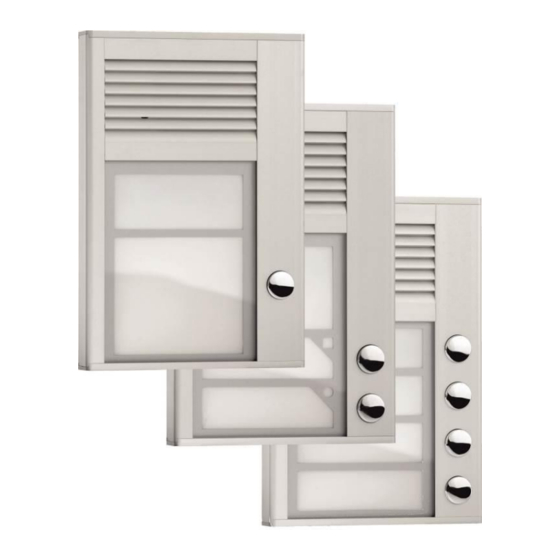
- Page 1 Brave – Door Entry System Brave SlimDP - 01 Brave SlimDP - 02 Brave SlimDP - 04 User and Service Manual Version 2.6...
- Page 3 24 digit telephone numbers including * # Flash and Pause; LED backlit name tags; Manual Version V2.6 22.10.2013 Alphatech Technologies s.r.o. Jeremenkova 88 140 00 Praha 4 Czech Republic, EU www.alphatechtechnologies.cz BRAVE SlimDP – User and service manual...
-
Page 4: Table Of Contents
Table of Contents BASIC FEATURES ..................... 6 .................... 6 EATURES ..................7 ERMINOLOGY ......... 8 RAVE VERSIONS AND DIFFERENCES ..................8 NIT FEATURES INSTALLATION ....................9 ......... 9 PENING WIRING WALL MOUNTING AND SETTINGS 2.1.1 Name card panel ..................9 2.1.2 Uncover control elements ................. - Page 5 ..............25 IRECT DIALLING MEMORY ....................26 ELAYS ................31 ASIC PARAMETERS ................33 IME PARAMETERS ................. 37 YSTEM PARAMETERS ............. 43 ASIC SETTING AND DELETION ............... 43 ND OF PROGRAMMING ............... 44 ARAMETER OVERVIEW TECHNICAL PARAMETERS................. 47 ..............47 LECTRICAL PARAMETERS ..............
-
Page 6: Basic Features
1 Basic features 1.1 Features Voice communication is powered from a telephone line Impulse and tone (DTMF) options Storage of 2 24-digit long numbers per button (including*, #, Flash and pause) Option to prolong a call with * or # ... -
Page 7: Terminology
1.2 Terminology Telephone line Analogue (2 conductors) connecting to a public telephone network (public line) or to a local telephone system (local line). Line connection The start of a telephone connection (the same as picking up a phone handset). Line disconnection End of connection (the same as replacing a phone handset). -
Page 8: Brave Slimdp Versions And Differences
1.3 Brave SlimDP versions and differences The Brave door entry system is conceived as system that provides a final solution based on a modular design. The features and parameters that are available to, and can be set, differ for each version of the Brave. It is therefore necessary to set the parameters for all versions including any add-on parameters for each version. -
Page 9: Installation
2 Installation This compact unit is fixed by 2 screws to the wall. 2.1 Opening, wiring, wall mounting and settings 2.1.1 Name card panel 1. Every unit is supplied with a special key which is used to release the name cards on the front panel. -
Page 10: Wiring And Wall Mounting
2.1.3 Wiring and wall mounting 5. Use the wall mounting template at the end of the manual to mark the position for the screw holes cable connection mounting surface. Drill the holes. 6. Feed cable (analogue line, power – supply, lock figure - 6) through the cable hole. - Page 11 The wiring of relay contacts is explained in the next picture. The symbol "NO" means contact normally open, "COM" means sharing output (central) and "NC" means contact normally closed. The relay contact is isolated from the other circuits on the board. For the variants of lock connection see the picture below.
-
Page 12: Switches
2.1.4 Switches 8. The switch marked HEAT (see figure – 8) activates heating of the PCB. This is increased resistance against humidity. To use this feature you must connect an external 12V power supply. 9. The switch marked SERVICE (see figure –... -
Page 13: Voice Level
2.1.5 Voice level The principle of setting acoustic paths: Here we have three parameters 71.72 and 73 Using the interaction of these parameters can be set to sound in different conditions. 1. quiet environment parameters 71,72,73 are set to 7 2. -
Page 14: Location Of Doorphone Components
2.2 Location of Doorphone components All mounting, control and setting elements are located under the speaker front aluminium grille. Loudspeaker Heating LED for activation lighting Service switch PC connector SlimDoorPhone fixing screw hole 12V =/~ for Telephone relay, light and line heating connection... -
Page 15: Changing Name Cards
2.3 Changing name cards pocket Name card panel (2.1.1on page 9) has spaces to insert printed name cards. Insert name cards from top (see picture). Cards can easily be printed with pictures as well as text using the included software. The card outline is marked for easy cutting . Panel with cards 2.4 Final closing of Doorphone... -
Page 16: Connect The Keyboard
2.5 Connect the Keyboard Keyboard work as separate code lock, he has connection power supply 12V, input for departure button and one relay with change-over contact. In case connection by special cable keyboard with Doorphone characteristics those code lock expand and keyboard can be use not only to control relay in keyboard, but relay in doorphone Doorphone contol too and use so 10 codes for one and 10 codes for second relay. -
Page 17: Code Relay (Cosw)
2.6 Code relay (COSW) For the switch (relay) is available function code relay (COSW CodeSwitch). It serves primarily to secure transmission of information by switching the electric lock. When using this function is not possible connecting or disconnecting the voltage at the terminals to lock this lock activated. Activation is performed only when positive result compared serial information transmitted between Brave and the board code relay... -
Page 18: Other Accessories
2.7 Other accessories 2.7.1 Time Relay time relay enables wider functionality of the relays. It is a separate product detailed instructions found www.alphatechtechnologies.cz 2.7.2 Power supply 12V AC A 12V/1A AC alternative power supply is recommended for the Brave SlimDP normal version. -
Page 19: Door Entry System Operation
3 Door Entry System Operation The Brave SlimDP door entry system’s functions are set by establishing parameters (see the chapter on parameter programming page 23). 3.1 Signalling overview Brave SlimDP acoustic signals that occur during its operation. Samples of sounds can be listened to in the setting programme ‘BraveSet’. State Tones Tone frequency... - Page 20 and presses the button. The Brave will pick up a line, "plays" the pick up line tone (if it is not prohibited para.62) and dials the phone number saved under that button (parameter 1 or 2 depending on system regime). From the Brave’s speaker a ringing tone will be heard and Mr Smith’s phone will ring.
-
Page 21: Relays Regimes
3.3 Relays regimes Regime m = 1 (parameter 3111 and 3121) Action Note Parameter Relay Evaluation of correct 3211-3215 According to setting 3311-3315 internal code from Day/Night 3411-3415 the buttons 321* 331* According to setting Day/Night 341* Internal code from Option to choose 1 or 2 digits of code the phone... -
Page 22: Incoming Call
sends a notice about the end of the call but choosing a code (parameter 42) it is possible to pro-long the call. By replacing the handset the call is terminated (the switchboard phone will send a system busy tone and the system will disconnect). -
Page 23: Parameter Programming
4 Parameter programming 4.1 Programming with the help of a phone 4.1.1 Entry into the programming There are two ways to enter the Brave’s programming system: 1. With the help of a password –incoming calls only! – pick up a phone and dial the number that the Brave is connected to (either the number of the branch, if you are connected to a switchboard line, or the number of the... -
Page 24: Programming With The Help Of Apc - Programme Brave Set
Note. If you want to keep a connection opened during the programming (prolong the 30 sec time) regime (i.e. before a customer decides what else he wants to be set) then you can press * or #, the Brave immediately answers with an error tone but will prolong the time before disconnecting. -
Page 25: Description Of Programmable Parameters
5 Description of programmable parameters Parameters always start with a fixed/mandatory part (address) followed by a variable part, which is your choice. The range and explanation is always under the table, sometimes with examples. Everything is dialled exactly as it is shown in the table, nothing needs to be confirmed in any way, after writing into a memory a confirmation tone can be heard and if an incorrect value is input then an error tone will be heard. -
Page 26: Relays
Note. If you are not using regime Day/night or regime 2 groups of numbers, then it is recommended to set regime Day/Night (parameter 47) and then set the same code for switching over Day/Night (parameters 45 and 46). His way it is guaranteed that Brave will always be in Day regime and you can only programme telephone numbers for the day regime (parameter 1). - Page 27 Parameter Value Meaning Basic In regime Day + Night password hh... for rp hh... relay r, in order p=1-5 for 1 impulse and p=* for 2 impulses (11-444444) In regime Day password hh... for relay r, rp hh... in order p=1-5 for 1 impulse and p=* for 2 impulses (11-444444) In regime Night password hh...
- Page 28 Example: 1 relay switch on internal code 48 – is programmed 35148 ♫ 2 relay switch on internal code 8 - is programmed 352*8 ♫ By choosing no 8 on the phone we switch on just the second relay, with option 48 we switch on both relays Note: second relay is in SlimKey module, works only if is SlimKey connected.
- Page 29 Parameter Value Meaning Basic relay r control during incoming call 11 21 (0/1) – relay number relay number [1 in SlimDP] p – parameter whether it is allowed p=1 or disallowed p=0 to control relay during incoming call. To prohibit ‘control’ during an incoming call, for use with relay 2 in mode 1 for controlling a garage door, so the electronics open the garage door and the car passing through the door, closes the door.
- Page 30 Parametr Value Description Default activation code 1 pulse from phone abcd 0000 (0000-1111) abcd – Brave sends a serial code for the code relay (COSW) after evaluation code from telephone (DTMF) namely for 1 pulse Parametr Value Description Default activation code 2 pulses from buttons abcd 0000 (0000-1111)
-
Page 31: Basic Parameters
5.3 Basic parameters Parameter Value Meaning Basic Type of choice v – time/impulse (0/1) v – type of choice v=0 is DTMF tone choice, v=1 is impulse choice Parameter Value Meaning Basic Sign for call prolonging (* / #) z – sign for prolonging a call * or # (10secs. before the end of the call the Brave sends signal, after pressing this the Brave prolongs the call) Parameter Value... - Page 32 Parameter Value Meaning Basic Command for switch over to DAY (00-99,*0-*9) Command for switchover to NIGHT (0099,*0-*9) command to switch over to the DAY regime [2 spaces] / command to switch over to the NIGHT regime [2 spaces] / command is always 2 digits, but if you wish to switch over from Day to Night with a single digit from the phone, there is an option to input "*a", where a is a single number and the star represents an empty space and must be in the first place...
-
Page 33: Time Parameters
5.4 Time parameters Parameter Value Meaning Basic Number of rings before the Brave picks up (1-9) q – The number of rings before an incoming call is picked up. The Brave picks up between rings 2 secs. after detecting the q-th ring. It is possible to set the number of rings between 1 and 9. - Page 34 Parameter Value Meaning Basic Time before commencing a choice (1-5) z – Time [sec] after the Brave picks up, before it commences a choice [range 1-5]. This time is different for each switchboard phone system, but generally most operate within 2 seconds after a line is picked up. Parameter Value Meaning...
- Page 35 Parameter Value Meaning Basic Tone length of time for DTMF (tone) choice 10 (100ms) (04-16) Time of gap between DTMF tones 10 (100ms) (04-16) 1 (100ms) Length of flash time (1-6) 4 (800ms) Length of time of pause/digit gap (1-0) Length of DTFM tone choices is specified by the formulae: (the entered number) x 10 = time length of tone [ms] [range 04-16 which is 40-160ms]...
- Page 36 Parameter Value Meaning Basic preemphase DTMF (0/1) Listening in DTMF – level (1-4) Preemphase is the ratio of the upper and lower groups of DTMF frequencies. It is possible to choose ratio 2.2 dB - p=0 (Europe) or ratio 3.2dB - p=1 (Australia) Choice of DTMF volume levels (4 levels): Volume in DTMF [dB] s - choice...
-
Page 37: System Parameters
5.5 System parameters Parameter Value Meaning Basic Acoustic signals (confirmation, error,empty memory, end of call) (0/1) The Brave’s comes with standard acoustic signals. However, using parameter “z” it is possible to switch off the acoustic signals. The values are: Acoustic signals off; and Acoustic signals on. - Page 38 Parameter Value Meaning Basic Suppression of the reception DTMF from the microphone (0/1) Suppression of the reception DTMF from the microphone is off as a default i=0. It is possible to open the door with a personal dialler without disturbing a person inside the building.
- Page 39 Parameter Value Meaning Basic Setting of the number of buttons on the main panel. This constant serves a purpose to identify the no.1 button in the composition of the module. After entering the number of buttons s the button no 1 is moving so it is always first.
- Page 40 5.6 Parameter setting Hands Free First ensure that the rubber seal on the microphone fits properly, otherwise setting the acoustic parameters will be difficult. Parameter Value Meaning Basic Reception volume 01-16 (16 is the highest) (SPK) Transmission volume 01-16 (16 is the highest) (MIC) Speaker volume...
- Page 41 Parameter Value Meaning Basic Threshold for switching on the microphone 1-4 (4 is the highest) There is a simultaneous signal from the microphone and the speaker on the telephone line, to ensure that the Brave doesn’t produce acoustic feedback. In the Hands Free circuit there are several functioning blocks for supressing this feedback.
- Page 42 Parameter Value Meaning Basic Compensation for loss of conduit depending on line current (0/1/2) The Brave has a circuit for installations remote from the switchboard (>100m) that can compensate for the loss caused by a conduit. This function is switched off as standard k=0, but it is possible to set on 2 levels, depending on the current that switchboard can supply (short circuit current I Switchboard current...
-
Page 43: Basic Setting And Deletion
5.7 Basic setting and deletion Parameter Value Meaning Basic provide Basic setting This setting does not affect parameters 1 and 2 (numbers saved in memory) Parameter Value Meaning Basic Deletes all numbers in 1st group (regime Day) Deletes all numbers in 2nd group (regime night) only 3.. -
Page 44: Parameter Overview
5.9 Parameter overview Parameter Value Meaning Basic tt nn… number nn under button tt tt nn… number nn under button tt 11 21 relay r works in regime m (1-6) button tt causes switching on of relay r in r* tt 1*01 regime m=6 (01-04) - Page 45 xxxx 0000 Service password (0000-9999) Command for switch over to DAY (00-99,*0-*9) Command for switch over to NIGHT (0099,*0-*9) Regime system choice (0/1) Line disconnection by repeat press of the same button (0/1) Umber of rings before Brave picks up (1-9) Maximum length of call (0-9,*,#)
- Page 46 Baby Call – call without the need to programme in number (0/1) Mute at the lock activated (0/1) Setting of number of buttons on the main panel Delayed start for switchboards with line tests (Siemens) (0/1) Reception volume 01-16 (16 is the highest) (SPK) Transmission volume...
-
Page 47: Technical Parameters
6 Technical parameters Electrical parameters Parameter Value Conditions Minimum line current 18mA Line picked up Minimum line voltage Line disconnected Voltage on the line when Brave < 8V I = 20mA picks up (VA characteristic) < 12V I = 60 mA Lead in in disconnected state <... -
Page 48: Table For Easy Programming
7 Table for easy programming Fill in the values you want to programme into the empty part of the table, in the double framed part there are whole programming commands to make programming easier. You can keep the programmed values in the manual for future changes. - Page 49 311* Button choice for 1 relay Switch on r 1 from phone 1 impulse Switch on r 2 from phone 1 impulse On keyboard - option 2 impulses Switch on r 1 from phone Length of time for r 1 switch [sec] Control of r 1 during 1 / 0...
- Page 50 Frequency of tone detector table Number of busy tones Length of time of permanent tone Length of time of tone nn x 10 choice Gap between DTMF tones nn x 10 Length of time Flash n x 100 Length of time of pause / n x100+400 Transmitting level DTMF 04-16...
- Page 51 WARRANTY: Each and every product has been tested before it leaves the factory. The manufacturer guarantees that the product and its features will work in accordance with the descriptions in this manual as long as the customer uses the product in accordance with the manufacturer’s instructions. Warranties will be extended when a warranty repair has been undertaken.
-
Page 52: Drilling Master Board
8 Drilling master board... - Page 53 © JR 2013 Version 2.6 X/13...
Need help?
Do you have a question about the Brave series and is the answer not in the manual?
Questions and answers