Advertisement
Quick Links
Advertisement

Subscribe to Our Youtube Channel
Related Manuals for Alphatech GSM-Variobell


Summary of Contents for Alphatech GSM-Variobell
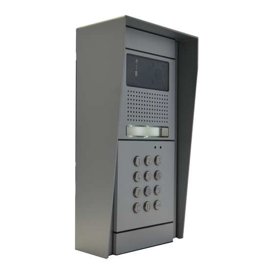
- Page 1 D O O R I N T E R C O M GSM-VarioBell www.alphatechtechnologies.cz User manual V 1.0...
- Page 2 Basic technical parametres: Power supply: 12 (9-24) V AC/DC, 500mA (optionally integrated ACU 2000mAh for cca 48h of operation) GSM : 850/900/1800/1900 MHz modular system – via table dimension: buttons: 1 or 2 in basic solution. Possibility extend up to 87 buttons + keypad (for every button max.
- Page 3 Voice signalling of different events (for example. „ wait please“, „Open“ , etc... SMS sending with date, time and numbers list from which was relay activated by ringing; date and time and code when relay is activated by keypad code. Function: Hands free GSM phone –...
- Page 4 a. From numbers saved in phone book on the SIM card only b. From any telephone number. 2. By code – during voice communication (incoming as same as outgoing call) . The 1 digit code by DTMF might be dialled by called party for relay activation ( for preprogrammed time).
- Page 5 Bell generates into a call short beeps for time of input activation. Voice signalling of different status. Up settings might be different status signalling by voice . ( language adjustable). When is voice signalling presented during a call it is hearable on both sides of connection (for example „open“) Detection of start/restart.
- Page 6 Button module VBDx-mod: VBD5-mod with 5 buttons VBD10-mod with 10 buttons Buttons order numbering is setup by DIP switch on each module (viz. follow). Keypad module VBDKey Keypad connection is not neccessary setup and not depends on position where is connected (via followe).
- Page 7 Mechanical parts For easier explanation we show mechanical parts for 1, 2 and 3 modules. In one column are max 3 modules. The big set contents max 3 columns ( 9 modules). For even bigger sets you can put 9 modules set over or next each other. Mounting box for flush mounting: Mounting box-1 Mounting box-2...
- Page 8 Fixing and covering frame – for flush and surface mounting For 1 module for 2 modules for 3 modules design frame – flush mounting only Frame-1 Frame-2 Frame-3 Frame - 3 x 2...
- Page 9 roofing shield – flush mounting only Shield-1 Shield-2 Shield -2 x 2 SMB – surface mounting boxi – surface mounting only (fixing frames are extra) SMB-1 SMB-2 SMB-3...
- Page 10 control elements and connection SIM reader SIM reader Switch of backup Insert SIM for Insert SIM for battery. For operation operation operation to ON position restart button Expanding modules connector input Relay Relay...
- Page 11 Signalling Speaker loudness regulation speaker microphone BBUTTON ABUTTON...
- Page 12 Examples of relays connection Basic connection - 2 electrical locks and possibility control 2 doors 2x PSU – possibility to use 2x PSU independently. First for GSM-VB and second for electrical locks.Electrical lock number is connected reversally (emergency exit). Activation of external camera or light. Combination of electrical lock and external bell.
- Page 13 Connection of extending modules VBD10(5)-mod Buttons extending modules are VBD10-mod with 10 buttons and VBD5-mod with 5 buttons. Buttons numbering will be explain further but it is done on each button module by DIP switch (6). PCB board with components VBDx-mod is connected to button module by screw terminal only (5) and via 3 wire cable (4).
- Page 14 Example of connection VBD10-mod and VBDKey Connection of each extending modules is done by flat cable K1. Nearest extending module to basic module is connected by cable K2. Modules numbering is setup by DIP switches (6) of each module. It not depends on connection order of each module but on DIP switch setting.
- Page 15 Buttons numbering Modules button numbering depends on DIP switch setting only. Button name is allways descripe by alphabetic B (button), button number (via button numbering) and after dash by order marking of phone number assigned to button. For example: B1-1 is mark of phone number for button 1 which will be dialled as first in order (etc..
- Page 17 Modules numbering is on picture. In left part are modules with 5 buttons VBD5-mod and in right part are moduleswith 10 buttons VBD10-mod. The module with desired number you find on this picture and next on the left is combination of DIP switch (6), which you have to setup on module!
- Page 18 Keypad VBDKey connection Keypad modul is connected by the same flat cable as button modules VBD10(5)-mod Cancel of pressed character (Back Space) Symbol to insert the password (code) Dial or memory number is perform by progressive pressing of number buttons. To insert password for door opening you have to press first button with key symbol cancel just inserted number press (Back Space).
- Page 19 Basic modul signalling on front panel mechanical front panel allows in basic modul window LED signalling of door phone status.This signalling follow requirement of handicap law. Bell symbol (red) – ringing during reaching call party Handset symbol (blue) – call picked up (speach) Open door symbol (green) –...
- Page 20 Installation...
- Page 21 Mounting process: A. Preparation of mounting holes in the wall – recommended height is about 160cm from ground. Dimension of holes depends on number of modules and here we mention dimensions for 1,2 and 3 modules (basic mounting boxes). The bigger sets are completed from those boxes by their combination ( under or next each other).
- Page 23 Start operation 1. connect antenna and insert the SIM we recommend use SIM without PIN. When is not possible setup PIN1234. by shift you release SIM holder from lock (1). lift up the holder (2). Insert the SIM in correct direction (3) into holder.
- Page 24 setup GSM-VB after switching ON via bellow descriped procedures. When you want to use call reject ( ringing) then ask GSM operator to deactivate your voice mail on used SIM card! SIM card preprogramm 1. SIM which you will use in GSM-VB insert to various mobile phone.
- Page 25 2. Switch ON GSM-VB When you have connected required wires (relays, locks,etc...) CAUTION for antenna, connect power supply. Red LED will light up and after few seconds start flashing yellow LED (via table). The GSM-VB by tones eventually by voice signalling SIM card reading, logging to GSM network and readiness for operation (via table).
- Page 26 1. During first setting when SIM doesnt contents any ADMINx name is neccessary such number insert to SIM by SMS with command INIT. SMS you can send from various number. When SIM already contents even one number under name ADMINx the command is ignored. 2.
- Page 27 A) Parametres setting by PC and programm GSMVBellset 1. Connect MiniUSB cable to PC as same as to programming module – green LED must light on at the module. During first usage USB driver might be installed. USB driver is available at attached CD or website . 2.
- Page 28 After click to monitor button is possible monitor operation in GSM-VB (when operation is not stoped by button STOP) Report saving from monitor to file (for support purposes – report sending) Mode programming After button STOP pressing programm sends to GSM-VB command to STOP and wait for GSM-VB feedback (via picture) Waiting for GSM-VB...
- Page 29 folder Buttons It is design to programm phone numbers under each button and for coopeartion with keypad (insert phone numbers to memory and insert codes) One button folder Field to programm up to 7 phone numbers for one button Field to programm up to 7 phone numbers for right button Folder for two buttons...
- Page 30 Folder for expanding button modules List of all memories and phone numbers of each buttons saved on SIM card. List is arranged according buttons. List of all memories and phone numbers for button selected from list on the right (by click on various memory of this button) ON/OFF function „Buttons Detect”.
- Page 31 Edit of selected number (insert number instead of „P“) Select button to edit List of edit with all appropriates phone numbers saved on SIM for this button (here just one record – P) After click to selected memory (here just one – B2-1) will occur in edit fields each elements of record (via description of previous page) Order in dialling...
- Page 32 Adding of button (function for automatic button detect wasnt used) Process similiary like in previous example (click on „Add Button“). BUT is neccessary: i. setup required button number ii. setup required order of phone number in dialling Those parametres in previous example (adding number to order for preselected button) have been created automatically.
- Page 33 Folder for keypad module Folder to work with memories Direct dialling of phone number from keypad. Dialled number is firstly searched between memories of phone numbers. When dont find the number then dial number to GSM network Waiting time for next number dial. When you exceed the time the previous dialled numbers are sent to unit (memory number or direct phone number) Work with phone numbers memories saved under selected...
- Page 34 Folder for keypad module Folder for work with codes (passwords) for relay activation (opening) Correction system, erasing and inserting new passwords is similiar as in previous. Work with codes will be descriped in follow text. Adding code Erasing selected code List of codes saved on SIM Position on SIM 33:C444C[2#4#10#14#**#0]...
- Page 35 Work with codes (passwords) 5 modes of codes (M0-M4) After code selection from list will be automatically setup appropriate folder. When you insert new password you have to select appropriate folder ( according required code features) manually. Name under which is password saved on SIM Every folder has: Field to insert number of code...
- Page 36 Simpliest mode – selected relay will close after inserted code from keypad for preprogrammed time. (via parametr time of relay activation further in manual) After code insert the relay close in preprogrammed days of week only.The GSM-VB might also calculate number of used codes and when number exceed preprogrammed value (for example number of prepaid entrances) the code is refused.
- Page 37 After inserting the code relay is activated in range of setup dates (included). Code using might be announced by sending SMS with date, time and used codes Setting of month and day from which is access permitted Setting of month and day until which is access permitted After code insert the relay is activated from setup date.
- Page 38 After inserting the code relay is activated in range of setup hours (working time). The GSM-VB might also calculate number used codes when number exceed preprogrammed value (for example number of prepaid entrances) the code is refused. Code using might be announced by sending SMS with date, time and used codes.
- Page 39 Folder Phone Book Phone book of authorised numbers to activate relay by ringing and automatic calls receiving. Position for name Position for phone number Add row on top of row with cursor Erase row with cursor Find inserted name...
- Page 40 Folder Setting – parametres setting Folder Calls csacallshovo Setting loudness of speaker Setting loudnes of microphone Way of calls receiving: - do not receive (open by ringing) - automatically pick up calls from numbers from list only - pick up all calls Signalling - inform tones of GSM-VB - incoming call ringing...
- Page 41 Folder relay Setting parametres for relay 1 Setting parametres for relay 2 Relay modes: - camera - light - button - control by SMS - control by code or ringing Relay control by ringing from numbers saved on SIM only Relay control by ringing from any number DTMF code to activate relay...
- Page 42 Folder SMS Number where is sent SMS „ALARM ON” when input is activated Number where is sent SMS „ALARM OFF” when input is deactivated Input mode: - Input deactivated - Tones when input is activated during a call (opening signalling) - SMS sending SMS sending to ADMIN1 with list of numbers from which was...
- Page 43 Folder ADMIN numbers setting Field to save up to 7 ADMIN numbers When all neccessary is setup then save all by button „Save“ to GSM-VB. (when you did setup buttons ,passwords or memories in extending modules – they are saved automatically when you press button „Write…“.
- Page 44 Return from programming mode to monitor mode (restart of GSM-VB) For return to monitor mode (start of GSM-VB) click on button „Run“. Programm detects start of GSM-VB the same way as stop: GSM-VB behaves after restart the same way as during power supply connection (tones, eventually voice info).
- Page 45 Table of commands for SMS Příkaz ( SMS) Funkce Def. READ STAT GSM-VB status reading (version, 4as, status, rel0 etc.) READ PAR Reading of all set parametres READ JMENO Reading of phone number for NAME CLR JMENO Erase of phone number for NAME INIT ADMIN1 +420cc…c First setting of GSM-VB –...
- Page 46 0 – OFF 1 - ON WRITE PAR TMGSM:x Setup time according GSM network x: 0 – OFF 1 - ON WRITE PAR TONE:x Setting of sound signalling x: 0 - OFF 1 – ON with service tones 2 – ON ringing of incoming call 4 –...
- Page 47 x=4 – close for „activation time“ after button press x=5 – extra switch mode (by ringing from any number or by code) WRITE PAR RL1TMON:yy Activation time for relay 1 after ringing or by code activation yy seconds yy=00-99 WRITE PAR RL1RING:x Relay 1 activation by ringing x=0 –...
- Page 48 y sec y= 1-9 WRITE PAR DDIAL:x permitt/ prohibit direct dialling from keypad: x=0 – prohibit x=1 – permitted Write number for SMS „ALARM ON“ WRITE ALARMON +420cc..c (input grounding) Write number for SMS „ALARM WRITE ALARMOFF OFF“ +420cc..c (input disconnect) CAL AT+CSQ GSM signal strength level CAL AT+CPBR=x...
- Page 49 Commands type: READ – command to read parametres and phone numbers from SIM. It means also reading of phone numbers saved under buttons (for example READ B1-1), in memories (for example READ M1234-1), codes setting (for example READ C123C) or parametres of GSM-VB in internal format (READ PARGDI) CLR - command to erase phone numbers from SIM...
- Page 50 Meaning of names saved in phone book jméno činnost ABUTTON1 - this number is called by GSM-VB when button is pressed (right) - by ringing activate relay 1 and relay 2 - from this number are automatically received the calls ABUTTON2 - this number is called by GSM-VB when number under button ABUTTON1 is not reachable , busy or not pick up the calls...
- Page 51 BBUTTON1 this number is called by GSM-VB when buttonon left is pressed (version with 2 buttons) - by ringing activate relay 1 and relay 2 na číslo - from this number are automatically received the calls BBUTTON2 this number is called by GSM-VB when number under button BBUTTON1 is not reachable , busy or not pick up the calls - by ringing activate relay 1 and relay 2 - from this number are automatically received the calls...
- Page 52 ADMIN2 - by ringing activate relay 1 and relay 2 - By SMS activate relay 1 and relay 2 - By SMS read status and numbers in phone book ADMIN7 - By SMS edit numbers and names on SIM card - By SMS control other features (AT commands) - By SMS setup parametres - From those numbers are automatically pick up calls...
- Page 53 E - wednesday: 1 permitted, 0 prohibited F - thursday: 1 permitted, 0 prohibited G - friday: 1 permitted, 0 prohibited H - saturday: 1 permitted, 0 prohibited I - sunday: 1 permitted, 0 prohibited JJ – number of permitted access 00-99, ** - then number not limited K –...
- Page 54 - it is send to this number SMS „ALARM ON“ when input is closed ALARMON against ground - it is send to this number SMS „ALARM OFF“ when input is opened ALARMOFF - version fw in GSM-VB - informing only- not change! - GSM-VB parametres PARGDI A#B#C#D#E#F#G#H (default 4#4#0#0#1#5#0#2)
- Page 55 CC – closing time [00-99] D – closing of relay by ringing: 0 – off 1 – on PARRL2 - parametres for relay 2 A#B#CC#D (default 5#1#03#1) A – DTMF code for close relay during call [0-9] B – relay mode: 0 – SMS mode, control by SMS 1 –...
- Page 56 Answer of GSM-VB to SMS „READ STAT“ READ STATUS: VER: 101 BATTERY:4030mV TIME: "00/01/01,00:01:55" OPER: T-Mobile CZ INP:1 RL1:0 RL1:0 Answer of GSM-VB to SMS „READ PAR“ READ PAR: VOLIN:4 VOLOUT:4 INCALL:0 WRCALL:1 TMGSM:1 TONE:5 INPMOD:2 WAIT:20 RL1COD:5 RL1MOD:4 RL1TMON:03 RL1RING:1 RL2COD:6 RL2MOD:1...
- Page 57 Tones GSM-VB Except ordinary tones and signalling of GSM communication (ringing tone, busy tone, different operator messages), has GSM-VB own signalling (via setup possibilities). High tone- notification Middle high tone – control action ...
- Page 58 LED signalling Do not light Flashing space and light the same length Yellow LED PCB Short flashing in 2 sec. period ▌ ▌ ▌ Permanent light Do not light ...
- Page 59 GSM-VB with backup battery When you have GSM-VB with backup battery (included) after unit connection just turn a switch of backup battery to position „ON“ (via picture) Do not store GSM-VB with inserted backup battery and switch in position „ON“! You might demaged battery! It is out of warranty.
- Page 60 CAUTION! After battery inserting MUST NOT light up red LED – indicates wrong polarity. In this case také out battery immediatelly! After getting GSM-VB to operation by turn switch to position ON you connect backup battery We do not take any responsibility of unit demaging when is not keep descriped process.
- Page 61 Technical parametres: Dimension according used modules Operating position various temperatura: -20 to + 50°C Operating condition humidity: 10% ÷ 80% when 30° C power voltage 12 (9-24) V AC/DC, min. 500mA (optional backup battery Li-18650 min 2000mAh for cca 48h of operation) buttons 1 to 87 according used modules...
Need help?
Do you have a question about the GSM-Variobell and is the answer not in the manual?
Questions and answers