Vega VEGABAR 66 Operating Instructions Manual
Foundation fieldbus
Hide thumbs
Also See for VEGABAR 66:
- Operating instructions manual (80 pages) ,
- Operating instructions manual (80 pages) ,
- Operating instructions manual (76 pages)

Related Manuals for Vega VEGABAR 66


Summary of Contents for Vega VEGABAR 66
-
Page 1: Operating Instructions
Operating Instructions VEGABAR 66 Foundation Fieldbus Document ID: 36740 Process pressure/ Hydrostatic... -
Page 2: Table Of Contents
Adjustment system ......35 Setup steps ....... 36 VEGABAR 66 • Foundation Fieldbus... - Page 3 10.3 Dimensions ....... 70 Supplementary documentation Information: Supplementary documents appropriate to the ordered version come with the delivery. You can find them listed in chapter "Product description". Editing status: 2012-03-09 VEGABAR 66 • Foundation Fieldbus...
-
Page 4: About This Document
This symbol indicates special instructions for Ex applications. List The dot set in front indicates a list with no implied sequence. à Action This arrow indicates a single action. Sequence Numbers set in front indicate successive steps in a procedure. VEGABAR 66 • Foundation Fieldbus... -
Page 5: For Your Safety
During work on and with the device the required personal protective equipment must always be worn. 2.2 Appropriate use VEGABAR 66 is a suspension pressure transmitter for level and gauge measurement. You can find detailed information on the application range in chapter "Product description". -
Page 6: Safety Label On The Instrument
2.6 CE conformity This device fulfills the legal requirements of the applicable EC guidelines. By attaching the CE mark, VEGA provides a confirmation of successful testing. You can find the CE conformity declaration in the download area of "www.vega.com". -
Page 7: Product Description
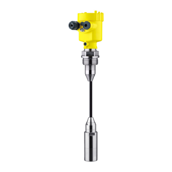
PLICSCOM" (optional) Supplementary instructions manual 31708 "Heating for in- dicating and adjustment module" (optional) Supplementary instructions manual "Plug connector for con- tinuously measuring sensors" (optional) VEGABAR 66 with suspension cable consists of the following Constituent parts components: Transmitter Suspension cable... - Page 8 3 Product description Fig. 1: Example of a VEGABAR 66 with suspension cable (left) and connection tube (right) Housing with integrated electronics Suspension cable Connection tube Threaded fitting Transmitter Protective cap VEGABAR 66 • Foundation Fieldbus...
-
Page 9: Principle Of Operation
In addition to the type label outside, you can also find the serial number on the inside of the instrument. 3.2 Principle of operation The VEGABAR 66 is a suspension pressure transmitter for level Application area measurement in wells, basins and atmospherically open vessels. -
Page 10: Operation
Foundation Fieldbus". The appropriate certificates are also available there. A CD with the appropriate files and certificates can be ordered via e-mail under info@de.vega.com or by phone from one of the VEGA agencies under the order number "DRIVER.S". The backlight of the indicating and adjustment module is powered by the sensor. -
Page 11: Packaging, Transport And Storage
Interface adapter communication-capable instruments to the USB interface of a PC. For parameter adjustment of these instruments, an adjustment software such as PACTware with VEGA-DTM is required. You can find further information in the operating instructions "Interface adapter VEGACONNECT" (Document-ID 32628). - Page 12 The electronics module is a replacement part for pressure transmitter VEGABAR. One version is available for each type of signal output. You find further information in the operating instructions "Electronics module VEGABAR series 50 and 60 " (Document-ID 30175). VEGABAR 66 • Foundation Fieldbus...
-
Page 13: Mounting
Fig. 3: Measures against moisture penetration Ventilation and pressure The ventilation of the electronics housing as well as the atmospheric compensation pressure compensation for the measuring cell are realised via a filter element in the area of the cable gland. VEGABAR 66 • Foundation Fieldbus... -
Page 14: Mounting Preparations
For the suspension cable version note the following points when selecting the mounting position: Sideways movements of the transmitter can cause measurement errors à Therefore, mount VEGABAR 66 in a calm area or in a suitable protective tube The suspension cable has a capillary for atmospheric pressure compensation à... - Page 15 It should only be removed when the sensor is deployed in extremely polluted water. Fig. 5: Mounting example: Version with connection tube in an open vessel Fig. 6: Mounting example: Version with suspension cable in a pump shaft VEGABAR 66 • Foundation Fieldbus...
-
Page 16: Mounting Steps With Straining Clamp
Suspension cable Suspension opening Clamping jaws Mount VEGABAR 66 with straining clamp as follows: Hang the straining clamp on a suitable wall hook Lower VEGABAR 66 to the requested height Slide the clamping jaws upward and push the suspension cable... -
Page 17: Mounting Steps With Screwed Connection
Mount VEGABAR 66 with screwed connection as follows: Weld the welded socket into the vessel top Lower VEGABAR 66 to the requested height by means on the welded socket G1½ A or 1½ NPT on the vessel side Insert the suspension cable from below into the open screwed... -
Page 18: Mounting Steps With Lock Fitting
Turn the upper hexagon into the lower hexagon. Spanner width SW 41, torque max. 80 Nm. VEGABAR 66 is now temporarily hold by the washer disc. Tighten fixing screws (2) and (5) with an Allen wrench size 2.5. -
Page 19: Mounting Steps With Housing And Thread
Housing Seal Thread Mount VEGABAR 66 with housing and thread in the following way: Mount into the vessel Weld the welded socket G1½ A or 1½ NPT to the vessel top Insert the transmitter with connection tube or suspension cable... -
Page 20: Mounting Steps, External Housing
The socket housing can be displaced by 180° to the wall mounting plate. Warning: The four screws of the socket housing must only be hand screwed. A torque > 5 Nm (3.688 lbf ft) can damage the wall mounting plate. VEGABAR 66 • Foundation Fieldbus... -
Page 21: Connecting To Power Supply
If overvoltage surges are expected, overvoltage arresters should be installed according to Foundation Fieldbus specification Tip: We recommend VEGA overvoltage arrester B63-32. In hazardous areas you must take note of the respective regulations, conformity and type approval certificates of the sensors and power supply units. -
Page 22: Connection Procedure
10 Connect the screen to the internal ground terminal, connect the outer ground terminal to potential equalisation 11 Tighten the compression nut of the cable entry. The seal ring must completely encircle the cable 12 Screw the housing cover back on VEGABAR 66 • Foundation Fieldbus... - Page 23 Loosen the four screws on the housing base with an Allen key size Remove the housing socket from the mounting plate Fig. 13: Components of the external housing Screws Wall mounting plate Cable gland VEGABAR 66 • Foundation Fieldbus...
-
Page 24: Wiring Plan, Single Chamber Housing
Remove approx. 5 cm of the cable mantle, strip approx. 1 cm insulation from the ends of the individual wires. After shortening the cable, fasten the type plate with sup- port back onto the cable. VEGABAR 66 • Foundation Fieldbus... -
Page 25: Wiring Plan, Double Chamber Housing
Display I 2 C Fig. 15: Wiring plan, single chamber housing Voltage supply, signal output 5.4 Wiring plan, double chamber housing The following illustrations apply to the non-Ex as well as to the Ex-ia version. VEGABAR 66 • Foundation Fieldbus... - Page 26 Internal connection cable to the connection compartment Connection compart- ment I 2 C Fig. 17: Connection compartment double chamber housing Spring-loaded terminals for voltage supply Plug connector for VEGACONNECT (I²C interface) Ground terminal for connection of the cable screen VEGABAR 66 • Foundation Fieldbus...
-
Page 27: Wiring Plan, Double Chamber Housing Ex D
Display I ² C 5 6 7 8 Fig. 19: Electronics compartment, double chamber housing Simulation switch ("on" = mode for simulation release) Connection for VEGACONNECT (I²C interface) Internal connection cable to the connection compartment VEGABAR 66 • Foundation Fieldbus... - Page 28 Fig. 20: Connection compartment, Ex-d double chamber housing Spring-loaded terminals for power supply and cable screen Ground terminal for connection of the cable screen Wiring plan Fig. 21: Wiring plan, Ex-d double chamber housing Voltage supply, signal output VEGABAR 66 • Foundation Fieldbus...
-
Page 29: Wiring Plan - Version Ip 66/Ip 68, 1 Bar
(+) and blue (-) to power supply or to the processing system Shielding 5.7 Wiring plan, external housing with version IP 68 Overview Fig. 23: VEGABAR 66 in IP 68 version 25 bar, non-Ex and axial cable outlet, external housing VEGABAR 66 • Foundation Fieldbus... - Page 30 Spring-loaded terminals for connection of the external indication VEGADIS Cable gland to the sensor Ground terminal for connection of the cable screen Spring-loaded terminals for Foundation Fieldbus connection Simulation switch ("on" = mode for simulation release) VEGABAR 66 • Foundation Fieldbus...
- Page 31 5 Connecting to power supply Terminal compartment, housing socket 1 2 3 4 Fig. 25: Connection of the sensor in the housing socket Brown Blue Yellow White Shielding Breather capillaries VEGABAR 66 • Foundation Fieldbus...
-
Page 32: Switch-On Phase
White Shielding Breather capillaries 5.8 Switch-on phase After VEGABAR 66 is connected to voltage supply or after voltage Switch-on phase recurrence, the instrument carries out a self-check for approx. 30 seconds. The following steps are carried out: Internal check of the electronics Indication of the instrument type, the firmware as well as the... -
Page 33: Set Up With The Indicating And Adjustment Module Plicscom
Screw housing cover with inspection window tightly back on Removal is carried out in reverse order. The indicating and adjustment module is powered by the sensor, an additional connection is not necessary. VEGABAR 66 • Foundation Fieldbus... - Page 34 Fig. 27: Insert indicating and adjustment module Note: If you intend to retrofit the instrument with an indicating and adjustment module for continuous measured value indication, a higher cover with an inspection glass is required. VEGABAR 66 • Foundation Fieldbus...
-
Page 35: Adjustment System
The functions of the individual keys are shown in the above illustration. Approx. 10 minutes after the last pressing of a key, an automatic reset to measured value indication is triggered. Any values not confirmed with [OK] will not be saved. VEGABAR 66 • Foundation Fieldbus... -
Page 36: Setup Steps
6 Set up with the indicating and adjustment module PLICSCOM 6.4 Setup steps VEGABAR 66 can be used for level as well as for process pressure Level or process press- ure measurement measurement. Default setting is level measurement. The mode can be changed in the adjustment menu. - Page 37 Unit of measurement Density 0001000 kg/dm³ Enter the requested density value with [->] and [+], confirm with [OK] and move to position correction with [->]. The adjustment unit is thus switched over from bar to m. VEGABAR 66 • Foundation Fieldbus...
- Page 38 Confirm with [+] and move to max. adjustment with [->]. The min. adjustment is finished. Information: For an adjustment with filling, simply enter the actual measured value indicated at the bottom of the display. Selection options: °C, °F. VEGABAR 66 • Foundation Fieldbus...
- Page 39 The editing procedure can be aborted with [ESC] or the displayed limit value can be accepted with [OK]. Process pressure measurement Set up VEGABAR 66 in the following sequence: Parameter ad- justment "Pro- Select application "Process pressure measurement"...
- Page 40 The actual measured value is displayed in addition to the menu items for zero/span adjustment. VEGABAR 66 is preset to application "Level measurement". Proceed Select application "Pro- as follows when switching over to application "Process pressure cess pressure measure- ment"...
- Page 41 Accept Edit Confirm with [OK] and move to min.(zero) adjustment with [->]. Carrying out zero ad- Proceed as follows: justment Edit the mbar value in the menu item "zero" with [OK]. Selection options: °C, °F. VEGABAR 66 • Foundation Fieldbus...
- Page 42 If the adjustment ranges are exceeded, the message "Outside parameter limits" appears. The editing procedure can be aborted with [ESC] or the displayed limit value can be accepted with [OK]. VEGABAR 66 • Foundation Fieldbus...
- Page 43 Span/Max. adjustment Measuring range end 1 kg/l Density Density unit kg/l Damping Linearisation Linear Sensor-TAG Sensor Display Displayed value AI-Out The values of the following menu items are not reset with "Reset: Sensor-specific basic adjustment. VEGABAR 66 • Foundation Fieldbus...
- Page 44 You will find a detailed description of these menu items in the operating instructions manual "Indicating and adjustment module". Special parameters are parameters which are set customer-specifically on the service level with the adjustment software PACTware. VEGABAR 66 • Foundation Fieldbus...
-
Page 45: Menu Schematic
Lighting ▼ AI-Out Switched off Diagnostics Basic adjustment Display ▶ Diagnostics Service Info 3.3.1 Peak value Sensor status Trend curve p-min.: -5.8 mbar p-max.: 167.5 mbar Start trend curve? T-min.: -12.5 °C T-max.: +85.5 °C VEGABAR 66 • Foundation Fieldbus... - Page 46 Level Info Basic adjustment Display Diagnostics Service ▶ Info Device-ID Instrument type Calibration date Last change using PC 26. August 2010 Sensor-TAG Software version 3.82 26. August 2010 Serial number 12345678 Sensor characteristics Display now? VEGABAR 66 • Foundation Fieldbus...
-
Page 47: Saving The Parameter Adjustment Data
They are thus available for multiple use or service purposes. If VEGABAR 66 is equipped with an indicating and adjustment module, the most important data can be read out of the sensor into the indicating and adjustment module. -
Page 48: Set Up With Pactware And Other Adjustment Programs
USB cable to the PC VEGACONNECT Sensor VEGACONNECT exter- nally TWIST Fig. 30: Connection via VEGACONNECT externally I²C bus (com.) interface on the sensor I²C connection cable of VEGACONNECT VEGACONNECT USB cable to the PC VEGABAR 66 • Foundation Fieldbus... -
Page 49: Parameter Adjustment With Pactware
A detailed description is available in the online help of PACTware and the VEGA DTMs. Note: Keep in mind that for setup of VEGABAR 66, DTM-Collection in the actual version must be used. All currently available VEGA DTMs are included as a DTM Collection on a CD. -
Page 50: Maintenance And Fault Rectification
24 hour service hotline Should these measures not be successful, please call in urgent cases the VEGA service hotline under the phone no. +49 1805 858550. The hotline is available to you 7 days a week round-the-clock. Since we offer this service world-wide, the support is only available in the English language. - Page 51 à Carry out a software update or send instrument for repair E041 Hardware error, electronics defective à Exchange the instrument or send it in for repair Fault message can also appear if the pressure is higher than the nominal range. VEGABAR 66 • Foundation Fieldbus...
-
Page 52: Calculation Of Total Deviation (According To Din 16086)
Level measurement 1500 mmWs Example Product temperature 40 °C, reference temperature 20 °C Selected: VEGABAR 66 with measuring range 0.2 bar Calculation ΔT: ΔT = 40 °C - 20 °C = 20 K Calculation of the set Turn Down: TD = 200 mbar/147 mbar, TD = 1.4 Basic accuracy digital output signal in percent: = √((F... -
Page 53: Exchanging The Electronics Module
These are not included in the electronics module without serial number. The serial number is stated on the type label of VEGABAR 66 or on the delivery note. 8.5 Software update... -
Page 54: Instrument Repair
Connect the signal conditioning instrument to power supply and provide the connection from the PC to the instrument via the interface adapter. Start PACTware and go via the menu "Project" to the VEGA project assistant. Select "USB" and "Set instruments online". Activate the project assistant with "Start". - Page 55 8 Maintenance and fault rectification Please ask the agency serving you for the address of your return shipment. You can find the respective agency on our website www.vega.com under: "Company - VEGA worldwide" VEGABAR 66 • Foundation Fieldbus...
-
Page 56: Dismounting
Correct disposal avoids negative effects on humans and the environ- ment and ensures recycling of useful raw materials. Materials: see chapter "Technical data" If you have no way to dispose of the old instrument properly, please contact us concerning return and disposal. VEGABAR 66 • Foundation Fieldbus... -
Page 57: Supplement
Seal between housing socket and wall TPE (fixed connected) mounting plate Seal between housing and housing NBR (stainless steel housing), silicone (Alu/plastic cover housing) Inspection window in housing cover for Polycarbonate (UL-746-C listed) PLICSCOM 316Ti/316L Ground terminal VEGABAR 66 • Foundation Fieldbus... - Page 58 -50 … 0 °C (-58 … +32 °F) typ. ±4 K and +100 … +150 °C (+212 … +302 °F) Input variable Adjustment Adjustment range of the min./max. adjustment relating to the nominal measuring range: -10 … 110 % Percentage value VEGABAR 66 • Foundation Fieldbus...
- Page 59 +290 psig -6 psig 0 … +6 psig +430 psig -12 psig 0 … +15 psig +500 psig -15 psig 0 … +35 psig +700 psig -15 psig Values less than -1 bar cannot be set. VEGABAR 66 • Foundation Fieldbus...
- Page 60 Thermal change zero signal and output span, reference temperature 20 °C (68 °F): < 0.05 %/10 K x TD In the compensated temperature range 0 … +100 °C (+32 … +212 °F) Incl. non-linearity, hysteresis and non-repeatability. VEGABAR 66 • Foundation Fieldbus...
- Page 61 -20 … +60 °C (-4 … +140 °F) Version with suspension cable PE Process conditions The specifications of the pressure stage and product temperature are used as an overview. The specifications on the type label are applicable. Process pressure, transmitter VEGABAR 66 • Foundation Fieldbus...
- Page 62 Limited by the overpressure resistance of the measuring cell. Tested according to the guidelines of German Lloyd, GL directive 2. Tested according to EN 60068-2-27. Depending on the version M12 x 1, according to ISO 4400, Harting, 7/8" FF. VEGABAR 66 • Foundation Fieldbus...
- Page 63 < 0.036 Ω/m (0.011 Ω/ft) Wire resistance > 1200 N (270 pounds force) Tensile strength 5 m (16.4 ft) Standard length 1000 m (3281 ft) Max. length Min. bending radius at 25 °C/77 °F 25 mm (0.985 in) VEGABAR 66 • Foundation Fieldbus...
- Page 64 Materials Housing Depending on the version M12 x 1, according to ISO 4400, Harting, 7/8" FF. With this extraction force, the suspension cable can be extracted out of the transmitter. VEGABAR 66 • Foundation Fieldbus...
- Page 65 Instruments with approvals can have different technical data depending on the version. That's why the associated approval documents have to be noted with these instruments. They are part of the delivery or can be downloaded under www.vega.com via "VEGA Tools" and "serial number search" as well as via "Downloads" and "Approvals".
-
Page 66: Information On Foundation Fieldbus
Channel = 2: Secondary Value 1 Channel = 3: Secondary Value 2 AI 3 Channel = 4: Temperature Fig. 32: Transducer Block VEGABAR 66 TB Transducer Block Function Block (AI =Analogue Input) Diagram, adjustment The following illustration shows the function of the adjustment:... - Page 67 X and Y values for the user defined linearization curve curve_points_21_30 X and Y values for the user defined linearization curve curve_points_31_33 X and Y values for the user defined linearization curve curve status VEGABAR 66 • Foundation Fieldbus...
- Page 68 Sensor value after the trim processing. Unit derives from 'Sensor_range.unit' sensor_sn Sensor serial number temperature Process temperature. Selected as input to AIFB by setting 'Channel' = 4. Unit derives from 'Temperature.unit' temperature_unit Unit code of 'Temperature', 'Max/Min_peak_temperature_value' °C, °F, K, °R VEGABAR 66 • Foundation Fieldbus...
- Page 69 Holds the maximum process temperature. Write access resets to current value. Unit derives from 'Temperature.unit' Write access resets to current value min_peak_temperature_value Holds the minimum process temperature. Write access resets to current value. Unit derives from 'Temperature.unit' Write access resets to current value VEGABAR 66 • Foundation Fieldbus...
-
Page 70: Dimensions
10 Supplement 10.3 Dimensions The following dimensional drawings represent only an extract of the possible versions. Detailed dimensional drawings can be downloaded on www.vega.com under "Downloads" and "Drawings". Plastic housing ~ 69 mm ~ 84 mm (3.31") (2.72") ø 79 mm ø... - Page 71 ø 86 mm ø 80 mm ø 79 mm (3.39") (3.15") (3.11") M16x1,5 M20x1,5/ ½ NPT M20x1,5/ M20x1,5/ ½ NPT ½ NPT Single chamber version, electropolished Single chamber version, precision casting Double chamber version, precision casting VEGABAR 66 • Foundation Fieldbus...
- Page 72 IP 68 version with external housing 65 mm ") 42mm ") 40mm ") 90 mm (3 ") 110 mm (4 ") ~ 66 mm (2 ") Fig. 39: IP 68 version with external housing Lateral cable outlet Axial cable outlet VEGABAR 66 • Foundation Fieldbus...
- Page 73 ø 44 mm ø 40 mm ") ") Fig. 40: VEGABAR 66 - standard version with straining clamp with threaded fitting G1½ A (1½ NPT) with thread G1½ A (1½ NPT), transmitter with PE plastic coating with direct cable outlet Lock fitting...
- Page 74 ø 21,3 mm ") ") ø 32 mm ") Fig. 41: VEGABAR 66 - transmitter 32 mm with straining clamp with threaded fitting G1½ A (1½ NPT) with thread G1½ A (1½ NPT) with direct cable outlet VEGABAR 66 • Foundation Fieldbus...
- Page 75 VEGABAR 66 SW 46 mm ") G1½A / SW 46 mm 1½”NPT ") G1½A / 1½”NPT Fig. 42: VEGABAR 66 - PVDF version with threaded fitting G1½ A (1½ NPT) with thread G1½ A (1½ NPT) VEGABAR 66 • Foundation Fieldbus...
- Page 76 4xø " " " 4xø 3" " " " " 4" 10" " " 8xø " " " Fig. 43: VEGABAR 66 - flange connection Flanges according to DIN 2501 Flanges according to ANSI B16.5 VEGABAR 66 • Foundation Fieldbus...
- Page 77 ø 78 mm (3 ") ø 92 mm (3 ") ") ø 8 mm ") ø 40 mm ") Fig. 44: VEGABAR 66 - hygienic fittings Clamp 2" (ø64 mm) PN16 DIN 32676, ISO 2852/316L Bolting DN 50 VEGABAR 66 • Foundation Fieldbus...
- Page 78 Les lignes de produits VEGA sont globalement protégées par des droits de propriété intellectuelle. Pour plus d'informations, on pourra se référer au site http://www.vega. VEGA lineas de productos están protegidas por los derechos en el campo de la propiedad industrial. Para mayor información revise la pagina web http://www.vega.com Линии...
- Page 79 Zero adjustment 41 Hotline 50 Installation - in the basin 19 - in the vessel 19 Maintenance 50 Max. adjustment 39 Min. adjustment 38 Moisture 13 Mounting external housing 20 Mounting position 13 Position correction 38, 41 VEGABAR 66 • Foundation Fieldbus...
- Page 80 All statements concerning scope of delivery, application, practical use and operating conditions of the sensors and processing systems correspond to the information avail- able at the time of printing. © VEGA Grieshaber KG, Schiltach/Germany 2012 36740-EN-120324 Subject to change without prior notice...
Need help?
Do you have a question about the VEGABAR 66 and is the answer not in the manual?
Questions and answers