Vega VEGABAR 82 Quick Setup Manual
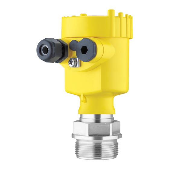
Pressure transmitter with ceramic measuring cell.
4...20 ma/hart
with sil qualification
Hide thumbs
Also See for VEGABAR 82:
- Operating instructions manual (104 pages) ,
- Quick setup manual (24 pages) ,
- Product information (16 pages)
Table of Contents
Advertisement
Quick Links
Download this manual
See also:
Quick Setup Manual
Advertisement
Table of Contents

Related Manuals for Vega VEGABAR 82


Summary of Contents for Vega VEGABAR 82
- Page 1 Quick setup guide Pressure transmitter with ceramic measuring cell VEGABAR 82 4 … 20 mA/HART With SIL qualification Document ID: 46308...
- Page 2 You can find supplementary information in the corresponding, more detailed Operating Instructions Manual as well as the Safety Manual that comes with instruments with SIL qualification. These manuals are available on the supplied DVD or in the download area of "www.vega. com". Operating instructions VEGABAR 82 - 4 … 20 mA/HART with SIL qualification: Document-ID 45030 Safety Manual VEGABAR series 80 - Two-wire 4 …...
-
Page 3: Authorised Personnel
During work on and with the device the required personal protective equipment must always be worn. Appropriate use The VEGABAR 82 is a pressure transmitter for process pressure and hydrostatic level measurement. You can find detailed information about the area of application in chapter "Product description". Operational reliability is ensured only if the instrument is properly used according to the specifications in the operating instructions manual as well as possible supplementary instructions. -
Page 4: Sil Qualification According To Iec 61508
The instrument meets the specifications of IEC 61508: 2010 (Edi- tion 2). It is qualified for single-channel operation up to SIL2. The instrument can be used homogeneously redundant up to SIL3 in multi-channel architecture with HFT 1. Permissible process pressure The permissible process pressure is specified on the type label with "Process pressure", see chapter "Configuration". For safety reasons, this range may not be exceeded. This applies even if a measuring cell with a measuring range (order-related) higher than the permissible pressure range of the process fitting is installed. VEGABAR 82 • 4 … 20 mA/HART... -
Page 5: Configuration
Test certificate (PDF) - optional Go to www.vega.com, "VEGA Tools" and "Instrument search". Enter the serial number. Alternatively, you can access the data via your smartphone: • Download the smartphone app "VEGA Tools" from the "Apple App Store" or the "Google Play Store" • Scan the Data Matrix code on the type label of the instrument or • Enter the serial number manually in the app... -
Page 6: Mounting 3.1 General Instructions For Use Of The Instrument
Fig. 2: Position of the filter element - non-Ex, Ex-ia and Ex-d-ia version Single chamber housing plastic, stainless steel (precision casting) Single chamber housing Aluminium Single chamber housing, stainless steel electropolished Double chamber housing plastic Double chamber housing Aluminium Filter element VEGABAR 82 • 4 … 20 mA/HART... - Page 7 With the following instruments a blind plug is installed instead of the filter element: • Instruments in protection IP 66/IP 68 (1 bar) - ventilation via capil- laries in non-detachable cable • Instruments with absolute pressure VEGABAR 82 • 4 … 20 mA/HART...
-
Page 8: Connecting To Power Supply 4.1 Connecting
1 cm (0.4 in) of insulation from the ends of the individual wires 5. Insert the cable into the sensor through the cable entry Fig. 3: Connection steps 5 and 6 - Single chamber housing VEGABAR 82 • 4 … 20 mA/HART... -
Page 9: Single Chamber Housing
9. Tighten the compression nut of the cable entry gland. The seal ring must completely encircle the cable 10. Reinsert the display and adjustment module, if one was installed 11. Screw the housing lid back on The electrical connection is finished. Single chamber housing The following illustration applies to the non-Ex, Ex-ia and Ex-d ver- sion. VEGABAR 82 • 4 … 20 mA/HART... -
Page 10: Double Chamber Housing
For display and adjustment module or interface adapter For external display and adjustment unit Ground terminal for connection of the cable screen Information: Parallel use of an external display and adjustment unit and a display and adjustment module in the terminal compartment is not supported. VEGABAR 82 • 4 … 20 mA/HART... -
Page 11: Set Up With The Display And Adjustment Module 5.1 Insert Display And Adjustment Module
3. Screw housing lid with inspection window tightly back on Disassembly is carried out in reverse order. The display and adjustment module is powered by the sensor, an ad- ditional connection is not necessary. Fig. 7: Installing the display and adjustment module in the electronics compart- ment of the single chamber housing VEGABAR 82 • 4 … 20 mA/HART... -
Page 12: Parameter Adjustment
The instrument is shipped in locked condition. To prevent unintentional or unauthorized adjustment, the instrument is protected (locked) against all parameter changes while in normal operating condition. For each parameter change you have to enter the PIN of the instru- ment. In delivery status, the PIN is "0000". VEGABAR 82 • 4 … 20 mA/HART... - Page 13 4. Depending on the application, carry out the adjustment e.g. in the menu items "Min. adjustment" and "Max. adjustment". Parameterization example VEGABAR 82 always measures pressure independently of the pro- cess variable selected in the menu item "Application". To output the selected process variable correctly, an allocation of the output signal to 0 % and 100 % must be carried out (adjustment).
- Page 14 3. Serial number acknowledgement Afterwards you confirm that the serial number of your instrument was carried over correctly. This is used to check device communication. 4. Verify parameters Confirm the modified values one after the other. If the described process of parameter adjustment was run through completely and correctly, the instrument will be locked and hence ready for operation. VEGABAR 82 • 4 … 20 mA/HART...
- Page 15 Current output in % Displayed value 2 Ceramic measuring cell: Measuring cell tempera- ture in °C Metallic measuring cell: Electronics temperature in °C Display format 1 and 2 Number of positions after the decimal point, auto- matically Backlight Switched on VEGABAR 82 • 4 … 20 mA/HART...
- Page 16 4 … 20 mA HART mode Address 0 Special pa- rameter (SIL) Menu - Info Menu item Parameter Device name VEGABAR 8. Instrument version Hardware and software version Factory calibration Date date Sensor characteristics Order-specific characteristics VEGABAR 82 • 4 … 20 mA/HART...
-
Page 17: Supplement 6.1 Technical Data
< 35 V) ≤ 1.0 V (16 … 400 Hz) Permissible residual ripple - Ex-d-ia instrument Ʋ for U 24 V DC (18 V< U < 35 V) ≤ 1 V (16 … 400 Hz) Load resistor Ʋ Calculation )/0.022 A Ʋ Example - Non-Ex instrument with (24 V - 9.6 V)/0.022 A = 655 Ω = 24 V DC VEGABAR 82 • 4 … 20 mA/HART... - Page 18 Notes VEGABAR 82 • 4 … 20 mA/HART...
- Page 19 Notes VEGABAR 82 • 4 … 20 mA/HART...
-
Page 20: Information
Subject to change without prior notice © VEGA Grieshaber KG, Schiltach/Germany 2016 VEGA Grieshaber KG Phone +49 7836 50-0 Am Hohenstein 113...
Need help?
Do you have a question about the VEGABAR 82 and is the answer not in the manual?
Questions and answers