Vega VEGABAR 66 Operating Instructions Manual
4...20 ma/hart
Hide thumbs
Also See for VEGABAR 66:
- Operating instructions manual (76 pages) ,
- Operating instructions manual (76 pages) ,
- Operating instructions manual (80 pages)

Related Manuals for Vega VEGABAR 66


Summary of Contents for Vega VEGABAR 66
-
Page 1: Operating Instructions
Operating Instructions VEGABAR 66 4 ... 20 mA/HART Document ID: 27537 Process pressure/ Hydrostatic... -
Page 2: Table Of Contents
Menu schematic ......47 Saving the parameter adjustment data ... . 49 VEGABAR 66 • 4 ... 20 mA/HART... - Page 3 The corresponding instructions manuals are: 32036 - Welded socket and seals 27720 - External indication VEGADIS 61 34296 - Protective cover 30175 - Electronics module VEGABAR series 50 and 60 VEGABAR 66 • 4 ... 20 mA/HART...
-
Page 4: About This Document
This symbol indicates special instructions for Ex applications. List The dot set in front indicates a list with no implied sequence. à Action This arrow indicates a single action. Sequence Numbers set in front indicate successive steps in a procedure. VEGABAR 66 • 4 ... 20 mA/HART... -
Page 5: For Your Safety
During work on and with the device the required personal protective equipment must always be worn. 2.2 Appropriate use VEGABAR 66 is a suspension pressure transmitter for level and gauge measurement. You can find detailed information on the application range in chapter "Product description". -
Page 6: Safety Approval Markings And Safety Tips
The range of available functions depends on the respective software version of the individual components. The software version of VEGABAR 66 can be determined as follows: via PACTware on the type label of the electronics via the indicating and adjustment module You can view all software histories on our website www.vega.com. - Page 7 2 For your safety Chapter "Packaging, transport and storage" Chapter "Disposal" VEGABAR 66 • 4 ... 20 mA/HART...
-
Page 8: Product Description
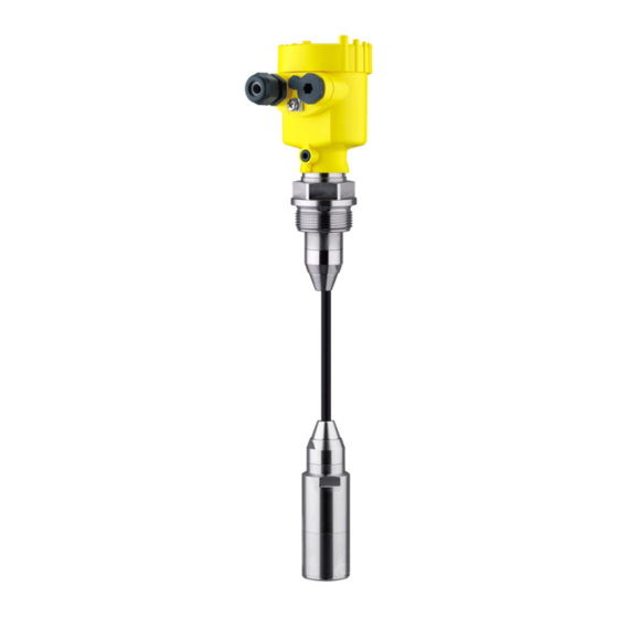
(optional) Supplementary instructions manual "Plug connector for con- tinuously measuring sensors" (optional) Ex-specific "Safety instructions" (with Ex-versions) if necessary, further certificates VEGABAR 66 with suspension cable consists of the following Components components: Transmitter Suspension cable External housing with electronics, optionally available with plug... - Page 9 3 Product description Fig. 1: Example of a VEGABAR 66 with suspension cable (left) and connection tube (right) Housing with integrated electronics Suspension cable Connection tube Screw connection Transmitter Protective cap The type label contains the most important data for identification and...
-
Page 10: Principle Of Operation
3 Product description 3.2 Principle of operation VEGABAR 66 is a suspension pressure transmitter for level Application area measurement in wells, basins and atmospherically open vessels. For use in atmospherically closed vessels under vacuum, the instrument is available with absolute pressure measuring ranges. -
Page 11: Packaging, Transport And Storage
Not exposed to corrosive media Protected against solar radiation Avoiding mechanical shock and vibration Storage and transport temperature see chapter "Supplement - Storage and transport temperature Technical data - Ambient conditions" Relative humidity 20 … 85 % VEGABAR 66 • 4 ... 20 mA/HART... -
Page 12: Mounting
Ventilation for the measuring cell is realised by means of a filter Ventilation element in the socket of the electronics housing. Ventilation for the electronics housing is realised via an additional filter element in the area of the cable glands. VEGABAR 66 • 4 ... 20 mA/HART... -
Page 13: Mounting Preparations
For the suspension cable version note the following points when selecting the mounting position: Sideways movements of the transmitter can cause measurement errors à Therefore, mount VEGABAR 66 in a calm area or in a suitable protective tube Information: We recommend the measuring instrument holder from the line of VEGA accessories (article no. - Page 14 It should only be removed when the sensor is deployed in extremely polluted water. Fig. 4: Mounting example: Version with connection tube in an open vessel Fig. 5: Mounting example: Version with suspension cable in a pump shaft VEGABAR 66 • 4 ... 20 mA/HART...
-
Page 15: Mounting Steps With Straining Clamp
Suspension cable Suspension opening Clamping jaws Mount VEGABAR 66 with straining clamp as follows: Hang the straining clamp on a suitable wall hook Lower VEGABAR 66 to the requested height Slide the clamping jaws upward and push the suspension cable... -
Page 16: Mounting Steps With Screwed Connection
Mount VEGABAR 66 with screwed connection as follows: Weld the welded socket into the vessel top Lower VEGABAR 66 to the requested height by means on the welded socket G1½ A or 1½ NPT on the vessel side Insert the suspension cable from below into the open screwed... -
Page 17: Mounting Steps With Lock Fitting
Turn the upper hexagon into the lower hexagon. Spanner width SW 41, torque max. 80 Nm. VEGABAR 66 is now temporarily hold by the washer disc. Tighten fixing screws (2) and (5) with an Allen wrench size 2.5. -
Page 18: Mounting Steps With Housing And Thread
Housing Seal Thread Mount VEGABAR 66 with housing and thread in the following way: Mount into the vessel Weld the welded socket G1½ A or 1½ NPT to the vessel top Insert the transmitter with connection tube or suspension cable... -
Page 19: Mounting Steps External Housing
The socket housing can be displaced by 180° to the wall mounting plate. Warning: The four screws of the socket housing must only be hand-screwed. A torque > 5 Nm (3.688 lbf ft) can damage the wall mounting plate. VEGABAR 66 • 4 ... 20 mA/HART... -
Page 20: Connecting To Power Supply
The data for power supply are specified in chapter "Technical data". Provide a reliable separation between the supply circuit and the mains circuits according to DIN VDE 0106 part 101. The VEGA power supply units VEGATRENN 149A Ex, VEGASTAB 690 as well as all VEGAMETs meet this requirement. -
Page 21: Connection Procedure
Check the hold of the wires in the terminals by lightly pulling on them 10 Connect the screen to the internal ground terminal, connect the outer ground terminal with potential equalisation VEGABAR 66 • 4 ... 20 mA/HART... - Page 22 The electrical connection is finished. Fig. 11: Connection steps 6 and 7 Proceed as follows: IP 68 version with exter- nal housing Loosen the four screws on the housing socket with an Allen key size 4 VEGABAR 66 • 4 ... 20 mA/HART...
- Page 23 5 cm of the cable mantle, strip approx. 1 cm insulation from the ends of the individual wires. After shortening the cable, fasten the type plate with sup- port back onto the cable. VEGABAR 66 • 4 ... 20 mA/HART...
-
Page 24: Wiring Plan, Single Chamber Housing
5.3 Wiring plan, single chamber housing The following illustrations apply to the non-Ex as well as to the Ex-ia version. Housing overview Fig. 13: Material versions, single chamber housing Plastic Aluminium Stainless steel Stainless steel casting VEGABAR 66 • 4 ... 20 mA/HART... -
Page 25: Wiring Plan, Double Chamber Housing
Fig. 15: Wiring plan, single chamber housing Voltage supply/Signal output 5.4 Wiring plan, double chamber housing The following illustration apply to non-Ex as well as Ex ia versions. The Exd version is described in the next subchapter. VEGABAR 66 • 4 ... 20 mA/HART... - Page 26 Display I ² C 5 6 7 8 Fig. 17: Electronics compartment, double chamber housing Plug connector for VEGACONNECT (I²C interface) Internal connection cable to the connection compartment Terminals for VEGADIS 61 VEGABAR 66 • 4 ... 20 mA/HART...
- Page 27 Plug connector for VEGACONNECT (I²C interface) Ground terminal for connection of the cable screen Spring-loaded terminals for voltage supply Wiring plan I 2 C Fig. 19: Wiring plan, double chamber housing Voltage supply/Signal output VEGABAR 66 • 4 ... 20 mA/HART...
-
Page 28: Wiring Plan Double Chamber Housing Ex D
Display I ² C 5 6 7 8 Fig. 21: Electronics compartment, double chamber housing Plug connector for VEGACONNECT (I²C interface) Internal connection cable to the connection compartment Terminals for VEGADIS 61 VEGABAR 66 • 4 ... 20 mA/HART... -
Page 29: Wiring Plan - Version Ip 66/Ip 68, 1 Bar
Fig. 23: Wiring plan double chamber housing Ex d Voltage supply/Signal output 5.6 Wiring plan - version IP 66/IP 68, 1 bar This version is only available for instruments with absolute pressure measuring ranges. VEGABAR 66 • 4 ... 20 mA/HART... -
Page 30: Wiring Plan, External Housing With Version Ip 68
(+) and blue (-) to power supply or to the processing system Shielding 5.7 Wiring plan, external housing with version IP 68 Overview Fig. 25: VEGABAR 66 in IP 68 version 25 bar, non-Ex and axial cable outlet, external housing VEGABAR 66 • 4 ... 20 mA/HART... - Page 31 Fig. 26: Electronics and connection compartment Plug connector for VEGACONNECT (I²C interface) Spring-loaded terminals for connection of the external indication VEGADIS Cable gland to VEGABAR Ground terminal for connection of the cable screen Spring-loaded terminals for voltage supply VEGABAR 66 • 4 ... 20 mA/HART...
- Page 32 Fig. 27: Connection of the sensor in the housing socket Brown Blue Yellow White Shielding Breather capillaries Wiring plan external electronics Display I 2 C Fig. 28: Wiring plan external electronics Power supply VEGABAR 66 • 4 ... 20 mA/HART...
-
Page 33: Switch On Phase
5 Connecting to power supply 5.8 Switch on phase After connecting VEGABAR 66 to power supply or after a voltage Switch on phase recurrence, the instrument carries out a self-check for approx. 30 seconds: Internal check of the electronics Indication of the instrument type, the firmware as well as the sensor TAGs (sensor designation) Output signal jumps briefly (approx. -
Page 34: Set Up With The Indicating And Adjustment Module Plicscom
Screw housing cover with inspection window tightly back on Removal is carried out in reverse order. The indicating and adjustment module is powered by the sensor, an additional connection is not necessary. VEGABAR 66 • 4 ... 20 mA/HART... - Page 35 Fig. 29: Mounting the indicating and adjustment module Note: If you intend to retrofit the instrument with an indicating and adjustment module for continuous measured value indication, a higher cover with an inspection glass is required. VEGABAR 66 • 4 ... 20 mA/HART...
-
Page 36: Adjustment System
The functions of the individual keys are shown in the above illustration. Approx. 10 minutes after the last pressing of a key, an automatic reset to measured value indication is triggered. Any values not confirmed with [OK] will not be saved. VEGABAR 66 • 4 ... 20 mA/HART... -
Page 37: Setup Procedure
DTM. HART mode Standard Address 0 VEGABAR 66 can be used for level as well as for process pressure Level or process pres- measurement. Default setting is level measurement. The mode can be sure measurement changed in the adjustment menu. - Page 38 Unit of measurement Density unit kg/dm³ ▶ Select the requested unit, e.g. kg/dm³ with [->] and confirm with [OK], the submenu "Density" appears. Selection options: mbar, bar, psi, Pa, kPa, MPa, inHg, mmHg, inH VEGABAR 66 • 4 ... 20 mA/HART...
- Page 39 +0000.0 mbar 0000.0 mbar Set the requested percentage value with [+] and [->]. Edit the requested mbar value with [OK]. Set the requested mbar value with [+] and [->]. Selection options: °C, °F. VEGABAR 66 • 4 ... 20 mA/HART...
- Page 40 "Outside parameter limits" appears. The editing procedure can be aborted with [ESC] or the displayed limit value can be accepted with [OK]. Process pressure measurement Set up VEGABAR 66 in the following sequence: Parameter ad- justment "Proc- Select application "Process pressure measurement"...
- Page 41 The actual measured value is displayed in addition to the menu items for zero/span adjustment. VEGABAR 66 is preset to application "Level measurement". Proceed Select application as follows when switching over to application "Process pressure "Process pressure...
- Page 42 53 mbar Select with [->], e.g. to accept actual measured value. Position correction Accept current measured value? ▶ Accept Edit Confirm with [OK] and move to min.(zero) adjustment with [->]. Selection options: °C, °F. VEGABAR 66 • 4 ... 20 mA/HART...
- Page 43 For an adjustment with pressure, you simply enter the displayed actual measured value. If the adjustment ranges are exceeded, the message "Outside parameter limits" appears. The editing procedure can be aborted with [ESC] or the displayed limit value can be accepted with [OK]. VEGABAR 66 • 4 ... 20 mA/HART...
- Page 44 [->] key. Caution: Note the following, if VEGABAR 66 is used as part of an overfill protection system according to WHG: If a linearisation curve is selected, the measuring signal is no longer compulsorily linear proportional to the level.
- Page 45 The values of the following menu items are not reset with "Reset: Menu section Function Reset value Basic settings Position correction no reset no reset Display Lighting no reset Service no reset Language HART mode no reset no reset Application VEGABAR 66 • 4 ... 20 mA/HART...
- Page 46 You will find a detailed description of these menu items in the operating instructions manual "Indicating and adjustment module". Special parameters are parameters which are set customer-specifically on the service level with the adjustment software PACTware. VEGABAR 66 • 4 ... 20 mA/HART...
-
Page 47: Menu Schematic
Basic adjustment ▶ Display Diagnostics Service Info Displayed value Displayed value Display unit ▼ Scaling 0 % = 0.0 ▼ ▼ Pressure Scaled Volume 100 % = 100.0 ▼ Lighting ▼ Switched off VEGABAR 66 • 4 ... 20 mA/HART... - Page 48 Display Diagnostics Service ▶ Info Sensor type Date of manufacture Last change using PC Sensor characteristics e.g. 16. May 2008 Software version Display now? Serial number e.g. 3.50 e.g. 16. May 2008 12345678 VEGABAR 66 • 4 ... 20 mA/HART...
-
Page 49: Saving The Parameter Adjustment Data
They are hence available for multiple use or service purposes. If VEGABAR 66 is equipped with an indicating and adjustment module, the most important data can be read out of the sensor into indicating and adjustment module. -
Page 50: Setup With Pactware And Other Adjustment Programs
VEGACONNECT Sensor External connection via I²C interface TWIST Fig. 32: Connection via I²C connection cable I²C bus (com.) interface on the sensor I²C connection cable of VEGACONNECT VEGACONNECT USB cable to the PC VEGABAR 66 • 4 ... 20 mA/HART... -
Page 51: Parameter Adjustment With Pactware
A detailed description is available in the online help of PACTware and the VEGA DTMs. Note: Keep in mind that for setup of VEGABAR 66, DTM-Collection in the actual version must be used. VEGABAR 66 • 4 ... 20 mA/HART... -
Page 52: Parameter Adjustment With Ams™ And Pdm
7 Setup with PACTware and other adjustment programs All currently available VEGA DTMs are provided in the DTM Collection on CD and can be obtained from the responsible VEGA agency for a token fee. This CD includes also the up-to-date PACTware version. -
Page 53: Maintenance And Fault Rectification
DTM. In many cases, the causes can be determined in this way and faults can be rectified. However, should these measures not be successful, call the VEGA 24 hour service hotline service hotline in urgent cases under the phone no. +49 1805 858550. - Page 54 Depending on the failure reason and measures taken, the steps Reaction after fault rec- described in chapter "Set up" must be carried out again, if necessary. tification Fault message can also appear if the pressure is higher than the nominal range. VEGABAR 66 • 4 ... 20 mA/HART...
-
Page 55: Calculation Of Total Deviation (Similar To Din 16086)
Level measurement 1500 mmWs Example Product temperature 40 °C, reference temperature 20 °C Selected: VEGABAR 66 with measuring range 0.2 bar Calculation ΔT: ΔT = 40 °C - 20 °C = 20 K Calculation of the set Turn Down: TD = 200 mbar/147 mbar, TD = 1.4 Basic accuracy digital output signal in percent: = √((F... -
Page 56: Exchanging The Electronics Module
These are not included in the electronics module without serial number. The serial number is stated on the type label of VEGABAR 66 or on the delivery note. 8.5 Software update... -
Page 57: Instrument Repair
Prepare update to the instrument via VEGACONNECT. Start PACTware and provide connection to the sensor, e.g. via the VEGA project assistant. Close the parameter window of the sensor, as far as open. Go in the PACTware menu bar to "Instrument data", "Additional Load software into sen- functions"... -
Page 58: Dismounting
Correct disposal avoids negative effects to persons and environment and ensures recycling of useful raw materials. Materials: see chapter "Technical data" If you have no possibility to dispose of the old instrument professionally, please contact us concerning return and disposal. VEGABAR 66 • 4 ... 20 mA/HART... -
Page 59: Supplement
Seal between housing socket and wall TPE (fixed connected) mounting plate Seal between housing and housing NBR (stainless steel housing), silicone (Alu/plastic cover housing) Inspection window in housing cover for Polycarbonate (UL-746-C listed) PLICSCOM Ground terminal 316Ti/316L VEGABAR 66 • 4 ... 20 mA/HART... - Page 60 20.5 mA, 22 mA, < 3.6 mA Max. output current 22 mA see load diagram under Power supply Load Fulfilled NAMUR recommendations NE 43 Dynamic behaviour output Run-up time approx. 10 s VEGABAR 66 • 4 ... 20 mA/HART...
- Page 61 +100 … +150 °C (+212 … +302 °F) Input variable Adjustment Adjustment range of the min./max. adjustment relating to the nominal measuring range: percentage value -10 … 110 % pressure value -20 … 120 % VEGABAR 66 • 4 ... 20 mA/HART...
- Page 62 0 … 900 psig 2900 psig -15 psig Absolute pressure 0 … 15 psi 500 psi 0 psi 0 … 35 psi 700 psi 0 psi Values less than -1 bar cannot be set. VEGABAR 66 • 4 ... 20 mA/HART...
- Page 63 Applies to digital interfaces (HART, Profibus PA, Foundation Fieldbus) as well as to analogue current output 4 … 20 mA. Specifications refer to the set span. Turn down (TD) = nominal measuring range/set span. Incl. non-linearity, hysteresis and non-repeatability. VEGABAR 66 • 4 ... 20 mA/HART...
- Page 64 Influence of the installation position < 0.2 mbar/20 Pa (0.003 psig) Limited by the overpressure resistance of the measuring cell. Limitation by the pressure-tightness of the cable connection. Limited by the overpressure resistance of the measuring cell. VEGABAR 66 • 4 ... 20 mA/HART...
- Page 65 < 2.5 mm² (AWG 14) tion Tested according to the regulations of German Lloyd, GL directive 2. Tested according to EN 60068-2-27. Depending on the version M12 x 1, according to DIN 43650, Harting, 7/ 8" FF. VEGABAR 66 • 4 ... 20 mA/HART...
- Page 66 1 x plug (depending on the version), 1 x blind stopper M20 x 1.5 Spring-loaded terminals for wire cross-sec- 2.5 mm² (AWG 14) tion up to Depending on the version M12 x 1, according to DIN 43650, Harting, 7/ 8" FF. VEGABAR 66 • 4 ... 20 mA/HART...
- Page 67 EEx-ia instrument 20 … 30 V DC EEx-d-ia instrument 20 … 36 V DC Permissible residual ripple < 100 Hz < 1 V 100 Hz … 10 kHz < 10 mV see diagram Load VEGABAR 66 • 4 ... 20 mA/HART...
- Page 68 Instruments with gauge pressure measuring ranges cannot detect the am- bient pressure when submerged, e.g. in water. This can lead to falsification of the measured value. Only with instruments with absolute pressure ranges. VEGABAR 66 • 4 ... 20 mA/HART...
- Page 69 Depending on the version, instruments with approvals can have different technical data. For these instruments, the corresponding approval documents have to be taken into account. These are part of the delivery or can be downloaded under www.vega.com via "VEGA Tools" and "serial number search" as well as via "Downloads" and "Approvals".
-
Page 70: Dimensions
Fig. 36: Housing versions in protection IP 66/IP 67 (with integrated indicating and adjustment module the housing is 9 mm/0.35 in higher) Plastic housing Stainless steel housing Special steel casting housing Aluminium double chamber housing Aluminium housing VEGABAR 66 • 4 ... 20 mA/HART... - Page 71 Fig. 37: Housing versions in protection IP 66/IP 68, 1 bar (with integrated indicating and adjustment module the housing is 9 mm/0.35 in higher) Stainless steel housing Special steel casting housing Aluminium double chamber housing Aluminium housing VEGABAR 66 • 4 ... 20 mA/HART...
- Page 72 65 mm ") 42mm ") 40mm ") 90 mm (3 ") 110 mm (4 ") ~ 66 mm (2 ") Fig. 38: IP 68 version with external housing Lateral cable outlet Axial cable outlet VEGABAR 66 • 4 ... 20 mA/HART...
- Page 73 ø 44 mm ø 40 mm ") ") Fig. 39: VEGABAR 66 - standard version with straining clamp with threaded fitting G1½ A (1½ NPT) with thread G1½ A (1½ NPT), transmitter with PE plastic coating with direct cable outlet Lock fitting...
- Page 74 ø 21,3 mm ") ") ø 32 mm ") Fig. 40: VEGABAR 66 - transmitter 32 mm with straining clamp with threaded fitting G1½ A (1½ NPT) with thread G1½ A (1½ NPT) with direct cable outlet VEGABAR 66 • 4 ... 20 mA/HART...
- Page 75 SW 46 mm ") G1½A / SW 46 mm 1½”NPT ") G1½A / 1½”NPT Fig. 41: VEGABAR 66 - PVDF version with threaded fitting G1½ A (1½ NPT) with thread G1½ A (1½ NPT) VEGABAR 66 • 4 ... 20 mA/HART...
- Page 76 " " " " 4xø " " 3" 4" 10" 8xø " " " " " Fig. 42: VEGABAR 66 - flange connection Flanges according to DIN 2501 Flanges according to ANSI B16.5 VEGABAR 66 • 4 ... 20 mA/HART...
- Page 77 ø 64 mm ø 78 mm (3 ") ø 92 mm (3 ") ") ø 8 mm ") ø 40 mm ") Fig. 43: VEGABAR 66 - hygienic fittings Tri-Clamp 2" Bolting DN 50 VEGABAR 66 • 4 ... 20 mA/HART...
-
Page 78: Industrial Property Rights
Les lignes de produits VEGA sont globalement protégées par des droits de propriété intellectuelle. Pour plus d'informations, on pourra se référer au site http://www.vega.com VEGA lineas de productos están protegidas por los derechos en el campo de la propiedad industrial. Para mayor información revise la pagina web http://www.vega.com Линии... - Page 79 10 Supplement VEGABAR 66 • 4 ... 20 mA/HART...
- Page 80 All statements concerning scope of delivery, application, practical use and operating conditions of the sensors and processing systems correspond to the information avail- able at the time of printing. © VEGA Grieshaber KG, Schiltach/Germany 2008 Subject to change without prior notice 27537-EN-081209...
Need help?
Do you have a question about the VEGABAR 66 and is the answer not in the manual?
Questions and answers