Vega VEGABAR 81 Quick Setup Manual
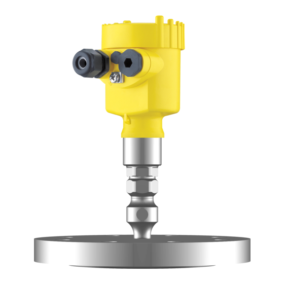
Pressure transmitter with chemical seal
Hide thumbs
Also See for VEGABAR 81:
- Operating instructions manual (96 pages) ,
- Quick setup manual (20 pages) ,
- Product information (16 pages)

Subscribe to Our Youtube Channel
Related Manuals for Vega VEGABAR 81


Summary of Contents for Vega VEGABAR 81
- Page 1 Quick setup guide Pressure transmitter with chemical seal VEGABAR 81 Profibus PA Document ID: 46302...
-
Page 2: Table Of Contents
Operating Instructions Manual as well as the Safety Manual that comes with instruments with SIL qualification. These manuals are available on the supplied DVD or in the download area of "www.vega. com". Operating instructions VEGABAR 81 - Profibus PA: Document-... -
Page 3: For Your Safety
During work on and with the device the required personal protective equipment must always be worn. Appropriate use The VEGABAR 81 is a pressure transmitter for process pressure and hydrostatic level measurement. You can find detailed information about the area of application in chapter "Product description". -
Page 4: Permissible Process Pressure
The environment management system is certified according to DIN EN ISO 14001. Please help us fulfill this obligation by observing the environmental instructions in this manual: • Chapter "Packaging, transport and storage" • Chapter "Disposal" VEGABAR 81 • Profibus PA... -
Page 5: Product Description
Alternatively, you can access the data via your smartphone: • Download the smartphone app "VEGA Tools" from the "Apple App Store" or the "Google Play Store" • Scan the Data Matrix code on the type label of the instrument or •... -
Page 6: Mounting
Fig. 2: Position of the filter element - non-Ex, Ex-ia and Ex-d-ia version Single chamber housing plastic, stainless steel (precision casting) Single chamber housing Aluminium Single chamber housing, stainless steel electropolished Double chamber housing plastic Double chamber housing Aluminium Filter element VEGABAR 81 • Profibus PA... - Page 7 With the following instruments a blind plug is installed instead of the filter element: • Instruments in protection IP 66/IP 68 (1 bar) - ventilation via capil- laries in non-detachable cable • Instruments with absolute pressure VEGABAR 81 • Profibus PA...
-
Page 8: Connecting To The Bus System
1 cm (0.4 in) of insulation from the ends of the individual wires 5. Insert the cable into the sensor through the cable entry Fig. 3: Connection steps 5 and 6 - Single chamber housing VEGABAR 81 • Profibus PA... -
Page 9: Single Chamber Housing
10. Reinsert the display and adjustment module, if one was installed 11. Screw the housing lid back on The electrical connection is finished. Single chamber housing The following illustration applies to the non-Ex, Ex-ia and Ex-d ver- sion. VEGABAR 81 • Profibus PA... -
Page 10: Double Chamber Housing
Electronics compartment 6 7 8 Fig. 6: Electronics compartment, double chamber housing Internal connection to the terminal compartment Contact pins for the display and adjustment module or interface adapter Selection switch for bus address VEGABAR 81 • Profibus PA... - Page 11 For external display and adjustment unit Ground terminal for connection of the cable screen Information: Parallel use of an external display and adjustment unit and a display and adjustment module in the terminal compartment is not supported. VEGABAR 81 • Profibus PA...
-
Page 12: Set Up With The Display And Adjustment Module
The display and adjustment module is powered by the sensor, an ad- ditional connection is not necessary. Fig. 8: Installing the display and adjustment module in the electronics compart- ment of the single chamber housing VEGABAR 81 • Profibus PA... -
Page 13: Parameter Adjustment - Quick Setup
In the first menu item you have to enter a sensor address. The selec- tion switches on the electronics module are preset to sensor address 126. This means that the sensor address can be changed via the display and adjustment module. VEGABAR 81 • Profibus PA... - Page 14 Enter the percentage value and the corresponding value for the max. level. 7. Min. adjustment In this menu item you carry out the min. adjustment for level Enter the percentage value and the corresponding value for the min. level. VEGABAR 81 • Profibus PA...
-
Page 15: Parameter Adjustment - Extended Adjustment
Menu and parameter Menu - Setup overview Menu item Parameter Default setting Instrument ad- dress Measurement Sensor loop name Application Application process pressure Slave for elec- Deactivated tronic differential pressure VEGABAR 81 • Profibus PA... - Page 16 Display format 1 and 2 Number of positions after the decimal point, auto- matically Backlight Switched on Menu - Diagnosis Menu item Parameter Default setting Sensor status Pressure Actual measured value Peak value Temperature Actual temperature values from meas- uring cell, electronics Simulation Process pressure VEGABAR 81 • Profibus PA...
- Page 17 Menu - Info Menu item Parameter Device name VEGABAR 8. Instrument version Hardware and software version Factory calibration Date date Profibus Ident Number Identification number of the instrument on a Profi- bus system Sensor characteristics Order-specific characteristics VEGABAR 81 • Profibus PA...
-
Page 18: Supplement
FISCO model Ʋ EEx-ia instrument - Power supply 13.5 … 24 V DC ENTITY model Ʋ Ex-d-ia instrument No lighting (integrated ia barrier) Number of sensors per DP/PA segment coupler, max. Ʋ Non-Ex Ʋ Ex VEGABAR 81 • Profibus PA... - Page 19 Notes VEGABAR 81 • Profibus PA...
-
Page 20: Information
Subject to change without prior notice © VEGA Grieshaber KG, Schiltach/Germany 2016 VEGA Grieshaber KG Phone +49 7836 50-0 Am Hohenstein 113...
Need help?
Do you have a question about the VEGABAR 81 and is the answer not in the manual?
Questions and answers