Vega VEGABAR 17 Operating Instructions Manual
Hide thumbs
Also See for VEGABAR 17:
- Operating instructions manual (36 pages) ,
- Operating instructions manual (37 pages) ,
- Operating instructions manual (37 pages)
Table of Contents
Advertisement
Quick Links
Advertisement
Table of Contents

Related Manuals for Vega VEGABAR 17


Summary of Contents for Vega VEGABAR 17
-
Page 1: Operating Instructions
Operating Instructions VEGABAR 17 Process pressure... - Page 2 Technical data ......24 Dimensions ....... 30 VEGABAR 17...
- Page 3 You can find them listed in chapter "Product description". Instructions manuals for accessories and replacement parts Tip: To ensure reliable setup and operation of your VEGABAR 17, we offer accessories and replacement parts. The associated documents are: 32036 - Welded socket and seals VEGABAR 17...
-
Page 4: Function
This symbol indicates special instructions for Ex applications. List The dot set in front indicates a list with no implied sequence. à Action This arrow indicates a single action. Sequence Numbers set in front indicate successive steps in a procedure. VEGABAR 17... -
Page 5: Authorised Personnel
During work on and with the device the required personal protection equipment must always be worn. 2.2 Appropriate use VEGABAR 17 is a pressure transmitter for measurement of gauge pressure, absolute pressure and vacuum. You can find detailed information on the application range in chapter "Product description". -
Page 6: Safety Approval Markings And Safety Tips
2.6 CE conformity This device fulfills the legal requirements of the applicable EC guidelines. By attaching the CE mark, VEGA provides a confirmation of successful testing. You can find the CE conformity declaration in the download area of "www.vega.com". -
Page 7: Configuration
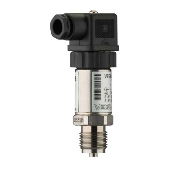
Ex-specific "Safety instructions" (with Ex-versions) if necessary, further certificates Configuration Fig. 1: VEGABAR 17 with plug connector according to DIN 43650-A Housing with electronics Process fitting Plug connector The type label contains the most important data for identification and... -
Page 8: Principle Of Operation
3 Product description 3.2 Principle of operation VEGABAR 17 is a pressure transmitter for measurement of gauge Area of application pressure, absolute pressure or vacuum. Measured products are gases, vapours and liquids. The front flush versions are also suitable for use in viscous or contaminated products. - Page 9 Dry and dust free Not exposed to corrosive media Protected against solar radiation Avoiding mechanical shock and vibration Storage and transport temperature see chapter "Supplement - Storage and transport temperature Technical data - Ambient conditions" Relative humidity 20 … 85 % VEGABAR 17...
-
Page 10: General Instructions
We recommend using lock fittings, measuring instrument holders and siphons from our line of accessories. 4.3 Mounting steps For mounting VEGABAR 17, a welded socket is required. You can find Welding the socket these components in the supplementary instructions manual "Welded socket and seals". - Page 11 4 Mounting à Screw VEGABAR 17 into the welded socket. Tighten the hexagon screw on the process fitting. Wrench size, see chapter "Dimen- sions", torque see chapter "Technical data". Fig. 2: Installation of VEGABAR 17 VEGABAR 17...
-
Page 12: Preparing The Connection
For the version with round plug connector M12 x 1, the suitable confectioned connection cable (article no. ASL.1S.) is available from the line of VEGA accessory with 5 m, 10 m or 25 m length. VEGABAR 17... -
Page 13: Connection Procedure
Connection via angle plug connector Loosen the screw on the rear of the plug connector Remove the plug connector and seal from VEGABAR 17 Remove the plug insert out of the plug housing Fig. 3: Loosen the plug insert Cable gland... - Page 14 Plug insert Plug seal Snap the plug insert into the plug housing and insert the sensor seal Plug the plug insert with seal to VEGABAR 17 and tighten the screw The electrical connection is finished. Proceed as follows: Connection via angle...
- Page 15 Connect the wire ends to the screw terminals according to the wiring plan Fig. 6: Connection to the screw terminals Cable gland Cover Plug housing Plug insert Plug seal Snap the plug insert into the plug housing and insert the sensor seal VEGABAR 17...
-
Page 16: Wiring Plan
Fig. 7: Wiring plan, angle plug connector according to DIN 43650-A, top view to VEGABAR 17 Voltage supply and signal output Round plug connector M12 x 1 Fig. 8: Wiring plan, round plug connector M12 x 1, top view to VEGABAR 17 Voltage supply and signal output VEGABAR 17... -
Page 17: Vegabar
(+) power supply and signal output green (-) power supply and signal output blue = cable screen Terminal housing – – Fig. 10: Wiring plan, terminal housing To power supply or the processing system Control instrument (4 … 20 mA measurement) VEGABAR 17... -
Page 18: Setup Procedure
6.1 Setup procedure After mounting and electrical connection, VEGABAR 17 is ready for operation. VEGABAR 17 delivers a current of 4 … 20 mA according to the actual process pressure. Further settings are not necessary. 6.2 Recalibration Zero and span can be readjusted via potentiometer. - Page 19 Screw on the housing cover in connected status Fig. 13: Adjustment zero and span zero span Adjust zero in unpressurized condition Set a span with a sufficiently precise reference pressure Check zero At least 3-times as exact as the pressure transmitter. VEGABAR 17...
- Page 20 6 Set up Screw the housing cover on VEGABAR 17...
-
Page 21: Maintenance
Fault rectification cases, the causes can be determined this way and the faults rectified. However, should these measures not be successful, call the VEGA 24 hour service hotline service hotline in urgent cases under the phone no. +49 1805 858550. -
Page 22: Instrument Repair
If a repair is necessary, please proceed as follows: You can download a return form (23 KB) from our Internet homepage www.vega.com under: "Downloads - Forms and certificates - Repair form". By doing this you help us carry out the repair quickly and without having to call back for needed information. -
Page 23: Dismounting Steps
Correct disposal avoids negative effects to persons and environment and ensures recycling of useful raw materials. Materials: see chapter "Technical data" If you have no possibility to dispose of the old instrument professionally, please contact us concerning return and disposal. VEGABAR 17... -
Page 24: Technical Data
For measuring ranges up to 25 bar not available. Halocarbon oil: In general in oxygen applications as well as in oil and grease-free applications, no with vacuum measuring ranges, not with ab- solute measuring ranges < 1 bar VEGABAR 17... - Page 25 0 … 400 bar/0 … 40 MPa 800 bar/80 MPa -1 bar/-100 kPa 0 … 600 bar/0 … 60 MPa 1200 bar/120 MPa -1 bar/-100 kPa 0 … 1000 bar/0 … 100 MPa 1500 bar/150 MPa -1 bar/-100 kPa VEGABAR 17...
- Page 26 Long-term stability (similar to DIN 16086, DINV 19259-1 and IEC 60770-1) Long-term drift of the zero signal < 0.2 %/year Relating to the adjusted span, incl. non-linearity, hysteresis and non-repro- ducibility. Relating to the set span, incl. hysteresis and repeatability. Under reference conditions, relating to the adjusted span. VEGABAR 17...
- Page 27 (176°F) 55°C (131°F) 130°C 150°C Proz (266°F) (302°F) Fig. 14: Temperature derating VEGABAR 17 Storage and transport temperature -30 … +105 °C (-22 … +221 °F) Process conditions Product temperature Standard -30 … +100 °C (-22 … +212 °F) additional -40 …...
- Page 28 RA ≤ (U-10V)/0,02 A- (length of the cable version in m x 0.14 Ω) Version with plug see diagram Version with terminal housing see diagram Ω Fig. 15: Voltage diagram VEGABAR 17 with plug Voltage limit Supply voltage Max. load VEGABAR 17...
- Page 29 Depending on the version, instruments with approvals can have different technical data. For these instruments, the corresponding approval documents have to be taken into account. These are part of the delivery or can be downloaded under www.vega.com via "VEGA Tools" and "serial number search" as well as via "Downloads" and "Approvals".
-
Page 30: Dimensions
G1/2B Fig. 17: VEGABAR 17 - dimensions with * in brackets apply to Ex versions, GDX = G½ B manometer connection, TBX = G½ B, inner G¼ B, 84L/84B = G1 B front-flush max. 25 bar, 851/85L/85B = G1 B front-flush with O-ring up to 1.6 bar, 861/86L/86B = G½... - Page 31 G1/2B Fig. 18: VEGABAR 17 - terminal housing, GDX = G½ B manometer connection, TBX = G½ B, inner G¼ B, 84L/84B = G1 B front-flush max. 25 bar, 851/85L/85B = G1 B front-flush with O-ring up to 1.6 bar, 861/86L/86B = G½ B front- flush with O-ring >...
- Page 32 9 Supplement VEGABAR 17...
- Page 33 9 Supplement VEGABAR 17...
- Page 34 9 Supplement VEGABAR 17...
- Page 35 9 Supplement VEGABAR 17...
- Page 36 All statements concerning scope of delivery, application, practical use and operating conditions of the sensors and processing systems correspond to the information avail- able at the time of printing. © VEGA Grieshaber KG, Schiltach/Germany 2008 Subject to change without prior notice 27636-EN-081029...
Need help?
Do you have a question about the VEGABAR 17 and is the answer not in the manual?
Questions and answers