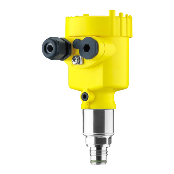
Vega VEGABAR 83 Operating Instructions Manual
Pressure transmitter with metallic
measuring cell.
4...20 ma/hart
with sil qualification
Hide thumbs
Also See for VEGABAR 83:
- Operating instructions manual (96 pages) ,
- Quick setup manual (24 pages) ,
- Product information (16 pages)

Related Manuals for Vega VEGABAR 83


Summary of Contents for Vega VEGABAR 83
-
Page 1: Operating Instructions
Operating Instructions Pressure transmitter with metallic measuring cell VEGABAR 83 4 … 20 mA/HART With SIL qualification Document ID: 45036... -
Page 2: Table Of Contents
Objective ........................37 6.2 SIL qualification ......................37 Application area ......................37 Safety concept of the parameterization ................38 Set up with the display and adjustment module ..............40 Insert display and adjustment module ................40 VEGABAR 83 • 4 … 20 mA/HART... - Page 3 12.6 Trademark ........................103 Safety instructions for Ex areas Take note of the Ex specific safety instructions for Ex applications. These instructions are attached as documents to each instrument with Ex approval and are part of the operating instructions manual. Editing status: 2017-11-14 VEGABAR 83 • 4 … 20 mA/HART...
-
Page 4: About This Document
Symbols used Document ID This symbol on the front page of this instruction refers to the Docu- ment ID. By entering the Document ID on www.vega.com you will reach the document download. Information, tip, note This symbol indicates helpful additional information. -
Page 5: For Your Safety
During work on and with the device the required personal protective equipment must always be worn. Appropriate use The VEGABAR 83 is a pressure transmitter for process pressure and hydrostatic level measurement. You can find detailed information about the area of application in chapter "Product description". Operational reliability is ensured only if the instrument is properly used according to the specifications in the operating instructions manual as well as possible supplementary instructions. -
Page 6: Eu Conformity
Germany. The published NAMUR recommendations are accepted as the standard in field instrumentation. The device fulfils the requirements of the following NAMUR recom- mendations: • NE 21 – Electromagnetic compatibility of equipment • NE 43 – Signal level for fault information from measuring transduc- • NE 53 – Compatibility of field devices and display/adjustment components • NE 107 – Self-monitoring and diagnosis of field devices Not fulfilled when connecting to an external display and adjustment unit. VEGABAR 83 • 4 … 20 mA/HART... -
Page 7: Installation And Operation In The Usa And Canada
That is why we have introduced an environment management system with the goal of continuously improving company environmental pro- tection. The environment management system is certified according to DIN EN ISO 14001. Please help us fulfil this obligation by observing the environmental instructions in this manual: • Chapter "Packaging, transport and storage" • Chapter "Disposal" VEGABAR 83 • 4 … 20 mA/HART... -
Page 8: Product Description
Alternatively, you can access the data via your smartphone: • Download the VEGA Tools app from the "Apple App Store" or the "Google Play Store" • Scan the Data Matrix code on the type label of the instrument or •... -
Page 9: Principle Of Operation
Optional instrument features are also described in this operating instructions manual. The respective scope of delivery results from the order specification. Principle of operation Measured variables The VEGABAR 83 is suitable for the measurement of the following process variables: • Process pressure •... - Page 10 3 Product description Fig. 2: Process pressure measurement VEGABAR 83 Electronic differential Depending on the version, the VEGABAR 83 is also suitable for pressure electronic differential pressure measurement. For this, the instrument is combined with a slave sensor. Fig. 3: Electronic differential pressure measurement through Master/Slave combination You can find detailed information in the operating instructions of the respective slave sensor.
- Page 11 3 Product description VEGABAR 83 is suitable for applications in virtually all industries. It is Application area used for the measurement of the following pressure types. • Gauge pressure • Absolute pressure • Vacuum Measured products are gases, vapours and liquids.
- Page 12 Pressure types The measuring cell design depends on the selected pressure type. Relative pressure: the measuring cell is open to the atmosphere. The ambient pressure is detected in the measuring cell and compen- sated. It thus has no influence on the measured value. VEGABAR 83 • 4 … 20 mA/HART...
-
Page 13: Supplementary Cleaning Procedures
Caution: The VEGABAR 83 in this version may not be used in oxygen ap- plications. For this purpose, instruments are available in the special version "Oil and grease-free for oxygen applications". -
Page 14: Packaging, Transport And Storage
Smartphone/tablet (iOS or Android operating system) • PC/notebook with Bluetooth USB adapter (Windows operating system) You can find further information in the operating instructions "Display and adjustment module PLICSCOM" (Document-ID 36433). Bluetooth function with VEGADIS 82 can only be used at a later date. VEGABAR 83 • 4 … 20 mA/HART... - Page 15 Slave sensors VEGABAR 83 an electronic differential pressure measurement. You can find further information in the operating instructions of the respective slave sensor. VEGADIS 81 The VEGADIS 81 is an external display and adjustment unit for VEGA plics sensors. ® For sensors with double chamber housing the interface adapter "VEGADIS adapter" is also required for VEGADIS 81.
- Page 16 The supplementary electronics is a replacement part for 4 … 20 mA/ ics for double chamber HART sensors with double chamber housing. housing You can find further information in the operating instructions "Supple- mentary electronics for 4 … 20 mA/HART - two-wire" (Document-ID 42764). VEGABAR 83 • 4 … 20 mA/HART...
-
Page 17: Mounting
The free openings for the cable glands are therefore covered with red dust protection caps as transport protection. The dust protection caps do not provide sufficient protection against moisture. VEGABAR 83 • 4 … 20 mA/HART... -
Page 18: Ventilation And Pressure Compensation
Ventilation and pressure compensation are carried out with VEGABAR 83 via a filter element. It is air permeable and moisture- blocking. Caution: The filter element causes a time-delayed pressure compensation. When quickly opening/closing the housing cover, the measured value can change for approx. 5 s by up to 15 mbar. For effective ventilation, the filter element must always be free of buildup. VEGABAR 83 • 4 … 20 mA/HART... - Page 19 • Instruments with absolute pressure Instruments in Ex-d ver- The filter element is integrated in the process assembly. It is located in sion a rotatable metal ring and has the following function: • Atmospheric pressure compensation (with relative pressure meas- uring ranges) VEGABAR 83 • 4 … 20 mA/HART...
- Page 20 The filter element is mounted into the electronics housing. It has the following functions: • Ventilation of the electronics housing • Atmospheric pressure compensation (with relative pressure meas- uring ranges) → Turn the housing so that the filter element points downward after the instrument is installed. This provides better protection against buildup. VEGABAR 83 • 4 … 20 mA/HART...
-
Page 21: Process Pressure Measurement
Instruments with absolute pressure have a blind plug mounted instead of the filter element. Process pressure measurement Measurement setup in Keep the following in mind when setting up the measuring system: gases • Mount the instrument above the measuring point Possible condensation can then drain off into the process line. VEGABAR 83 • 4 … 20 mA/HART... - Page 22 Keep the following in mind when setting up the measuring system: Measurement setup in vapours • Connect via a siphon • Do not insulate the siphon • Fill the siphon with water before setup VEGABAR 83 • 4 … 20 mA/HART...
- Page 23 < 100 °C on the transmitter is ensured. Measurement setup in Keep the following in mind when setting up the measuring system: liquids • Mount the instrument below the measuring point The effective pressure line is always filled with liquid and gas bubbles can bubble up to the process line. VEGABAR 83 • 4 … 20 mA/HART...
-
Page 24: Level Measurement
• Mount the instrument below the min. level • Do not mount the instrument close to the filling stream or emptying area • Mount the instrument so that it is protected against pressure shocks from the stirrer Fig. 15: Measurement setup for level measurement VEGABAR 83 • 4 … 20 mA/HART... -
Page 25: External Housing
1. Mark the holes according to the following drilling template 2. Fasten wall mounting plate with 4 screws 90 mm (3.54") 70 mm (2.76") 8 mm (0.12") (0.32") Fig. 17: Drilling template - wall mounting plate VEGABAR 83 • 4 … 20 mA/HART... -
Page 26: Connecting To Power Supply
Prior to setup you have to replace these protective caps with ap- proved cable glands or close the openings with suitable blind plugs. VEGABAR 83 • 4 … 20 mA/HART... -
Page 27: Connecting
4. Remove approx. 10 cm (4 in) of the cable mantle, strip approx. 1 cm (0.4 in) of insulation from the ends of the individual wires 5. Insert the cable into the sensor through the cable entry VEGABAR 83 • 4 … 20 mA/HART... - Page 28 "Technical data - Electromechanical data". 7. Check the hold of the wires in the terminals by lightly pulling on them 8. Connect the screen to the internal ground terminal, connect the external ground terminal to potential equalisation VEGABAR 83 • 4 … 20 mA/HART...
-
Page 29: Single Chamber Housing
The following illustrations apply to the non-Ex as well as to the Ex-ia version. Electronics compartment 4...20mA 6 7 8 Fig. 21: Electronics compartment - double chamber housing Internal connection to the terminal compartment For display and adjustment module or interface adapter VEGABAR 83 • 4 … 20 mA/HART... - Page 30 Current output (I) - Voltage supply of the sensor and signal output (with HART) Additional current output (II) - Voltage supply and signal output (without HART) Ground terminal for connection of the cable screen VEGABAR 83 • 4 … 20 mA/HART...
-
Page 31: Ex-D-Ia Double Chamber Housing
For display and adjustment module or interface adapter Internal connection to the plug connector for external display and adjust- ment unit (optional) Note: HART multidrop mode is not possible when using an Ex-d-ia instru- ment. VEGABAR 83 • 4 … 20 mA/HART... -
Page 32: Double Chamber Housing With Vegadis-Adapter
VEGADIS adapter Internal plug connection Plug connector M12 x 1 Assignment of the plug connector Fig. 28: View to the plug connector M12 x 1 Pin 1 Pin 2 Pin 3 Pin 4 VEGABAR 83 • 4 … 20 mA/HART... -
Page 33: Housing Ip 66/Ip 68 (1 Bar)
Brown (+) and blue (-) to power supply or to the processing system Shielding External housing with version IP 68 (25 bar) Overview Fig. 30: VEGABAR 83 in IP 68 version 25 bar with axial cable outlet, external housing Transmitter Connection cable External housing VEGABAR 83 •... -
Page 34: Power Supply
Cable gland for voltage supply Cable gland for connection cable, transmitter Terminal compartment, housing socket 1 2 3 4 Fig. 32: Connection of the sensor in the housing base Yellow White Black Shielding Breather capillaries VEGABAR 83 • 4 … 20 mA/HART... -
Page 35: Connection Example
Ground terminal for connection of the cable screen Connection example Connection example, ad- ditional current output 4...20mA 4...20mA Fig. 34: Connection example VEGABAR 83 additional current output Supply and signal circuit, sensor Signal circuit, additional current output Input card PLC Sensor Circuit... -
Page 36: Switch-On Phase
Output signal at instruments with current output jumps to the set fault current Then the actual measured value is outputted to the signal cable. The value takes into account settings that have already been carried out, e.g. default setting. VEGABAR 83 • 4 … 20 mA/HART... -
Page 37: Functional Safety (Sil)
SIL rating and can be also found on our homepage via the instrument search. Application area The instrument can be used, for example, for process pressure and hydrostatic level measurement of liquids in safety-instrumented sys- VEGABAR 83 • 4 … 20 mA/HART... -
Page 38: Safety Concept Of The Parameterization
The DTM suitable for the signal conditioning instrument in con- junction with an adjustment software according to the FDT/DTM standard, e. g. PACTware Note: For operation of the VEGABAR 83 an actual DTM Collection is re- quired. The modification of safety-relevant parameters is only possible with active connection to the instrument (online mode). Safe parameterization... - Page 39 Warning: Instrument reset In case of a reset to basic settings, all safety-relevant parameters will also be reset to default. Therefore all safety-relevant parameters must be checked or readjusted. VEGABAR 83 • 4 … 20 mA/HART...
-
Page 40: Set Up With The Display And Adjustment Module
The display and adjustment module is powered by the sensor, an ad- ditional connection is not necessary. Fig. 35: Installing the display and adjustment module in the electronics compart- ment of the single chamber housing VEGABAR 83 • 4 … 20 mA/HART... -
Page 41: Adjustment System
If you intend to retrofit the instrument with a display and adjustment module for continuous measured value indication, a higher lid with an inspection glass is required. Adjustment system Fig. 37: Display and adjustment elements LC display Adjustment keys • Key functions [OK] key: VEGABAR 83 • 4 … 20 mA/HART... - Page 42 (with inspection window) of the sensor housing. Fig. 38: Display and adjustment elements - with adjustment via magnetic pen LC display Magnetic pen Adjustment keys Bluetooth symbol Lid with inspection window VEGABAR 83 • 4 … 20 mA/HART...
-
Page 43: Measured Value Indication
- Display, Menu language". Parameter adjustment Main menu The main menu is divided into five sections with the following func- tions: Setup: Settings, e.g., for measurement loop name, application, units, position correction, adjustment, signal output Display: Settings, e.g., for language, measured value display, lighting VEGABAR 83 • 4 … 20 mA/HART... - Page 44 In digital systems and in the documentation of larger plants, a singular desig- nation must be entered for exact identification of individual measuring points. The available digits include: • Letters from A … Z • Numbers from 0 … 9 VEGABAR 83 • 4 … 20 mA/HART...
- Page 45 Setup - Application In this menu item you activate/deactivate the slave sensor for elec- tronic differential pressure and select the application. VEGABAR 83 can be used for process pressure and level measure- ment. Default setting is process pressure measurement. The mode can be changed in this adjustment menu.
- Page 46 Setup - Adjustment VEGABAR 83 always measures pressure independently of the pro- cess variable selected in the menu item "Application". To output the selected process variable correctly, an allocation of the output signal to 0 % and 100 % must be carried out (adjustment).
- Page 47 The editing procedure can be aborted with [ESC] or the displayed limit value can be accepted with [OK]. Setup - Span adjustment Proceed as follows: 1. Select with [->] the menu item Span adjustment and confirm with [OK]. VEGABAR 83 • 4 … 20 mA/HART...
- Page 48 Setup - Max. adjustment Proceed as follows: Level 1. Select with [->] the menu item Max. adjustment and confirm with [OK]. 2. Edit the percentage value with [OK] and set the cursor to the requested position with [->]. VEGABAR 83 • 4 … 20 mA/HART...
- Page 49 (SIL). Setup - Current output In the menu item "Current output mode" you determine the output (mode) characteristics and reaction of the current output in case of fault. VEGABAR 83 • 4 … 20 mA/HART...
- Page 50 You then have to carry out the character string comparison. This is used to check the character presentation. Confirm if the two character strings are identical. The verification texts are provided in German and in the case of all other menu languages, in English. 3. Serial number acknowledgement VEGABAR 83 • 4 … 20 mA/HART...
- Page 51 Otherwise the instrument remains in the released and hence unsafe condition. Information: As long as the VEGABAR 83 is powered, the display and adjustment module remains in the actually set adjustment menu. An automatic, time-controlled reset to the measured value indication is not carried out.
- Page 52 7 Set up with the display and adjustment module • Polish • Czech • Turkish In delivery status, the VEGABAR 83 is set to English. Display - Displayed value In this menu item, you define which measured value is displayed. 1 and 2 The default setting for the display value is "Lin. percent". Display - Display format In this menu item you define the number of decimal positions with 1 and 2 which the measured value is displayed.
- Page 53 Additional settings - After a reset, certain parameter adjustments made by the user are Reset reset. The following reset functions are available: Delivery status: Restores the parameter settings at the time of shipment from the factory, incl. the order-specific settings. Any user- VEGABAR 83 • 4 … 20 mA/HART...
- Page 54 Reset - Display Menu item Default value Menu language No reset Displayed value 1 Pressure Displayed value 2 Ceramic measuring cell: Measuring cell temperature in °C Metallic measuring cell: Electronics temperature in °C VEGABAR 83 • 4 … 20 mA/HART...
-
Page 55: Instrument Settings
• Write to sensor: Save data from the display and adjustment mod- ule back into the sensor The following data or settings for adjustment of the display and ad- justment module are saved: VEGABAR 83 • 4 … 20 mA/HART... - Page 56 (SIL). Additional settings - Cur- In menu item "Current output, variable" you specify which measured rent output 1 and 2 (size) variable the current output refers to. For instruments with SIL qualification, the selection is limited to lin. percent. VEGABAR 83 • 4 … 20 mA/HART...
- Page 57 PC. Info - Sensor character- In this menu item, the features of the sensor such as approval, pro- istics cess fitting, seal, measuring range, electronics, housing and others are displayed. VEGABAR 83 • 4 … 20 mA/HART...
-
Page 58: Saving The Parameterisation Data
If it is necessary to exchange a sensor, the display and adjustment module is inserted into the replacement instrument and the data are likewise written into the sensor via the menu item "Copy device settings". VEGABAR 83 • 4 … 20 mA/HART... -
Page 59: Setup With Pactware
Interface adapter, for example VEGACONNECT 4 Note: With power supply units with integrated HART resistance (internal resistance approx. 250 Ω), an additional external resistance is not necessary. This applies, e.g. to the VEGA instruments VEGATRENN 149A, VEGAMET 381, VEGAMET 391. Common Ex separators are VEGABAR 83 • 4 … 20 mA/HART... -
Page 60: Parameter Adjustment
In the standard version, all functions for complete setup are already included. An assistant for simple project configuration simplifies the adjustment considerably. Saving/printing the project as well as import/export functions are also part of the standard version. VEGABAR 83 • 4 … 20 mA/HART... -
Page 61: Saving The Parameterisation Data
The standard version is available as a download under www.vega.com/downloads and "Software". The full version is avail- able on CD from the agency serving you. Saving the parameterisation data We recommend documenting or saving the parameterisation data via PACTware. -
Page 62: Set Up With Other Systems
They can then be transferred to a Field Communicator. In the HART communication, the Universal Commands and a part of the Common Practice Commands are supported. VEGABAR 83 • 4 … 20 mA/HART... -
Page 63: Diagnosis, Asset Management And Service
10 s, with electronic differential pressure also the static pressure. The requested values and recording conditions are set via a PC with PACTware/DTM or the control system with EDD. Data are thus read out and also reset. VEGABAR 83 • 4 … 20 mA/HART... -
Page 64: Asset Management Function
PACTware/DTM or EDD. Out of specification: The measured value is unreliable because an instrument specification was exceeded (e.g. electronics temperature). This status message is inactive by default. It can be activated by the user via PACTware/DTM or EDD. Maintenance: Due to external influences, the instrument function is limited. The measurement is affected, but the measured value is VEGABAR 83 • 4 … 20 mA/HART... - Page 65 Error in the calibration carried Exchanging the electronics Bit 10 of Byte 0 … 5 • out in the factory Send instrument for repair Error in the cali- • Error in the EEPROM bration VEGABAR 83 • 4 … 20 mA/HART...
- Page 66 Use instrument with higher tronics temperature temperature range • • S603 Operating voltage below speci- Check electrical connection Bit 23-1 of • fied range If necessary, increase operating Byte 14 … 24 Impermissible oper- voltage ating voltage VEGABAR 83 • 4 … 20 mA/HART...
-
Page 67: Rectify Faults
Evaluation of fault messages via the adjustment device • Checking the output signal • Treatment of measurement errors Further comprehensive diagnostics options are available with a PC with PACTware and the suitable DTM. In many cases, the reasons can be determined in this way and faults rectified. VEGABAR 83 • 4 … 20 mA/HART... -
Page 68: Exchange Process Module On Version Ip 68 (25 Bar)
24 hour service hotline Should these measures not be successful, please call in urgent cases the VEGA service hotline under the phone no. +49 1805 858550. The hotline is also available outside normal working hours, seven days a week around the clock. -
Page 69: Exchanging The Electronics Module
10 Diagnosis, asset management and service Fig. 44: VEGABAR 83 in IP 68 version, 25 bar and lateral cable outlet, external housing Process module Plug connector Fixing screw Cable assembly Connection cable External housing 3. Loosen the plug connector 4. Mount the new process module on the measuring point 5. -
Page 70: Software Update
Make sure that you are using the correct software with SIL qualifica- tion. Instruments with SIL qualification can only be updated with a respec- tive software. An accidental update with a wrong software version is impossible. Caution: Instruments with approvals can be bound to certain software versions. Therefore make sure that the approval is still effective after a software update is carried out. You can find detailed information in the download area at www.vega.com. VEGABAR 83 • 4 … 20 mA/HART... -
Page 71: How To Proceed If A Repair Is Necessary
Clean the instrument and pack it damage-proof • Attach the completed form and, if need be, also a safety data sheet outside on the packaging • Please contact the agency serving you to get the address for the return shipment. You can find the agency on our home page www.vega.com. VEGABAR 83 • 4 … 20 mA/HART... -
Page 72: Dismount
Pass the instrument directly on to a spe- cialised recycling company and do not use the municipal collecting points. These may be used only for privately used products according to the WEEE directive. VEGABAR 83 • 4 … 20 mA/HART... -
Page 73: Supplement
Transmission liquid with measuring ranges up to 40 bar. With measuring ranges from 100 bar dry measuring cell. Halocarbon oil: Generally in oxygen applications, not with vacuum measuring ranges, not with absolute meas- uring ranges < 1 bar VEGABAR 83 • 4 … 20 mA/HART... - Page 74 Ʋ 7/16 NPT for tube ¼" 40 Nm (29.50 lbf ft) Ʋ 9/16 NPT for tube 3/8" 50 Nm (36.88 lbf ft) Between transmitter and external electronics housing. Fix connected to the sensor. VEGABAR 83 • 4 … 20 mA/HART...
- Page 75 0 … 40 bar/0 … 4000 kPa 120 bar/+12 MPa 0 bar abs. Nominal measuring ranges and overload capacity in psi Nominal range Overload capacity, max. pressure Overload capacity, min. pressure Gauge pressure VEGABAR 83 • 4 … 20 mA/HART...
- Page 76 0 … +10 bar/0 … +1000 kPa +50 bar/+5000 kPa -1 bar/-100 kPa 0 … +25 bar/0 … +2500 kPa +50 bar/+5000 kPa -1 bar/-100 kPa -1 … 0 bar/-100 … 0 kPa +35 bar/+3500 kPa -1 bar/-100 kPa VEGABAR 83 • 4 … 20 mA/HART...
- Page 77 0 … 15 psi 510 psi 0 psi 0 … 30 psi 725 psi 0 psi 0 … 150 psi 1300 psi 0 psi 0 … 300 psi 1900 psi 0 psi Adjustment ranges Specifications refer to the nominal measuring range, pressure values lower than -1 bar cannot be VEGABAR 83 • 4 … 20 mA/HART...
- Page 78 4 … 20 mA (passive) Range of the output signal 3.8 … 20.5 mA (default setting) Signal resolution 0.3 µA Last valid measured value not possible with SIL. The output values can be assigned individually. VEGABAR 83 • 4 … 20 mA/HART...
- Page 79 : dead time; t : rise time; t : jump response time Process variable Output signal VEGABAR 83 VEGABAR 83 - IP 68 (25 bar) Dead time ≤ 25 ms ≤ 50 ms Rise time (10 … 90 %) ≤ 55 ms ≤ 150 ms Step response time (ti: 0 s, 10 … 90 %) ≤ 80 ms...
- Page 80 70 °C -40 °C 10 °C 50 °C 100 °C 150 °C -0,15 -0,3 -0,45 -0,6 -0,75 T / °C -0,9 Fig. 46: Basic temperature error F at TD 1 : 1 TBasis Different availability depending on measuring range and process fitting VEGABAR 83 • 4 … 20 mA/HART...
- Page 81 Additional factor through measuring cell version Measuring cell - Standard Measuring cell version 0.075 %, 0.1 % 0.2 % Factor FMZ Additional factor through Turn Down VEGABAR 83 • 4 … 20 mA/HART...
- Page 82 Measuring range 1 bar < 0.15 % x TD/year Measuring range 0.4 bar < 0.35 % x TD/year With ceramic/metallic measuring cell with gold-coated diaphragm, the values must be multiplied with factor 3. VEGABAR 83 • 4 … 20 mA/HART...
-
Page 83: Ambient Conditions
40 °C (104 °F) 0 °C (32 °F) 85 °C 105 °C (185 °F) (221 °F) Fig. 49: Temperature derating VEGABAR 83, version up to +105 °C (+221 °F) Process temperature Ambient temperature Not with measuring ranges ≥100 bar in conjunction with flange 2500 lbs. VEGABAR 83 • 4 … 20 mA/HART... - Page 84 (32 °F) 85 °C 150 °C (185 °F) (302 °F) Fig. 50: Temperature derating VEGABAR 83, version up to +150 °C (+302 °F) Process temperature Ambient temperature SIP process temperature (SIP = Sterilization in place) Vapour stratification for 2 h +150 °C (+302 °F)
- Page 85 (140 °F) 0 °C (32 °F) 110 °C 150 °C (230 °F) (302 °F) Fig. 51: Temperature derating VEGABAR 83, version up to +150 °C (+302 °F) Process temperature Ambient temperature 80 °C (176 °F) 65 °C (149 °F) 0 °C (32 °F)
- Page 86 Wires, strain relief, breather capillaries, screen braiding, metal foil, mantle 2 g with housing version stainless steel double chamber IP 66/IP 68 (0.2 bar), only with absolute pressure. Breather capillaries not with Ex-d version. VEGABAR 83 • 4 … 20 mA/HART...
- Page 87 Configuration, connection cable Max. cable length Screened 4 … 20 mA/HART 50 m ● 4 … 20 mA/HART SIL Profibus PA, Foundation Fieldbus 25 m ● Interface to the slave sensor Data transmission Digital (I²C-Bus) Configuration, connection cable 4-wire, screened VEGABAR 83 • 4 … 20 mA/HART...
- Page 88 (16 … 400 Hz) Load resistor Ʋ Calculation )/0.022 A Ʋ Example - Non-Ex instrument with (24 V - 9.6 V)/0.022 A = 655 Ω = 24 V DC Potential connections and electrical separating measures in the instrument Electronics Not non-floating Ground terminal Galvanically connected with the metal process fitting VEGABAR 83 • 4 … 20 mA/HART...
-
Page 89: Calculation Of The Total Deviation
Instruments with approvals can have different technical specifications depending on the version. For that reason the associated approval documents of these instruments have to be carefully noted. They are part of the delivery or can be downloaded under www.vega.com, "Instrument search (serial number)" as well as in the download area. 12.2 Calculation of the total deviation The total deviation of a pressure transmitter indicates the maximum measurement error to be ex- pected in practice. -
Page 90: Calculation Of The Total Deviation - Practical Example
12.3 Calculation of the total deviation - Practical example Data Pressure measurement in the pipeline 4 bar (400 KPa), product temperature 40 °C VEGABAR 83 with measuring range 10 bar, deviation < 0.1 %, process fitting G1 (piezoresistive measuring cell) The required values for the temperature error F... - Page 91 - 2. step: Total deviation F total total perf stab = 0.26 % (result of step 1) perf = (0.1 % x TD) stab = (0.1 % x 2.5) stab = 0.25 % stab VEGABAR 83 • 4 … 20 mA/HART...
-
Page 92: Dimensions
The example shows that the measurement error in practice can be considerably higher than the basic accuracy. Reasons are temperature influence and Turn down. 12.4 Dimensions The following dimensional drawings represent only an extract of the possible versions. Detailed dimensional drawings can be downloaded at www.vega.com under "Downloads" and "Drawings". Plastic housing ~ 69 mm ~ 84 mm (2.72") - Page 93 Fig. 57: Housing version with protection rating IP 66/IP 68 (1 bar) - with integrated display and adjustment module the housing is 9 mm/0.35 in higher Aluminium - single chamber Aluminium - double chamber VEGABAR 83 • 4 … 20 mA/HART...
- Page 94 Fig. 59: Housing version with protection rating IP 66/IP 68 (1 bar) - with integrated display and adjustment module the housing is 9 mm/0.35 in higher Stainless steel single chamber (electropolished) Stainless steel single chamber (precision casting) Stainless steel double chamber housing (precision casting) VEGABAR 83 • 4 … 20 mA/HART...
- Page 95 ø 80 mm (3.15") M20x1,5/ ½ NPT Fig. 60: Housing version with protection rating IP 69K - with integrated display and adjustment module the housing is 9 mm/0.35 in higher Stainless steel single chamber (electropolished) VEGABAR 83 • 4 … 20 mA/HART...
- Page 96 (1.64") ~ 66 mm (2.60") 110 mm x 90 mm (4.33" x 3.54") Fig. 61: VEGABAR 83, IP 68 version with external housing Lateral cable outlet Axial cable outlet Plastic single chamber Stainless steel single chamber Seal 2 mm (0.079 in), (only with 3A approval)
- Page 97 ( 1.42 ") ½ NPT ½ NPT ¼ NPT Fig. 62: VEGABAR 83, threaded fitting not front-flush DU G½, EN 837; manometer connection C2 M20 x 1.5 EN 837; manometer connection DN G½, inside G¼, ISO 228-1 LF ½ NPT, inside ¼ NPT, ASME B1.20.1 LY ½...
- Page 98 ø 40 mm ø 40 mm (2.17") (1.59") (1.59") Fig. 63: VEGABAR 83, threaded fitting front-flush LU G½, ISO 228-1; front-flush; with O-ring C5 G1, ISO 228-1 DA G1½, DIN3852-A AF M44 x 1.25 DIN 13; pressure screw: Aluminium AG M44 x 1.25 DIN 13; pressure screw: 316L C9 1½...
- Page 99 ø 105 mm (3.60") (4.13") Fig. 64: VEGABAR 83, hygienic fitting 150 °C (piezoresistive/strain gauge measuring cell) AR Clamp 2" PN 16 (ø 64 mm) DIN 32676, ISO 2852 ES Hygienic connection with compression nut F40 PN 25 FR Varivent N50-40 PN 25 EZ Collar socket DN 40 PN 40, DIN 11851 E3 Collar socket DN 50 PN 25 Form A, DIN 11864;...
- Page 100 (3.07") (3.07") ø 105 mm (4.13") Fig. 65: VEGABAR 83, hygienic fitting 150 °C (METEC measuring cell) ® AR Clamp 2" PN 16 (ø 64 mm) DIN 32676, ISO 2852 ES Hygienic fitting with compression nut F 40 PN 25...
- Page 101 0.94" 6“ 4xø 0.75" 5“ 0.06" Fig. 66: VEGABAR 83, flange connection 150 °C (piezoresistive/strain gauge measuring cell) Flange connection according to DIN 2501 Flange connection according to ASME B16.5 Order-specific Order-specific For the version with "Second Line of Defense", the measure of length increases by 17 mm (0.67 in).
- Page 102 6“ 4xø 0.75" 5“ 0.12" Fig. 67: VEGABAR 83, flange connection 180 °C/200 °C (ceramic/metallic measuring cell) Flange connection according to DIN 2501 Flange connection according to ASME B16.5 Temperature adapter up to 180 °C Temperature screen sheet up to 200 °C...
-
Page 103: Industrial Property Rights
Les lignes de produits VEGA sont globalement protégées par des droits de propriété intellec- tuelle. Pour plus d'informations, on pourra se référer au site www.vega.com. VEGA lineas de productos están protegidas por los derechos en el campo de la propiedad indus- trial. Para mayor información revise la pagina web www.vega.com. - Page 104 – Mode 57 Linearisation 49 Maintenance 63 Measured value memory 63 Measurement setup 21, 22, 23, 24 NAMUR NE 107 64 – Function check 66 Parameterization example 46 Peak value indicator – Pressure 52 VEGABAR 83 • 4 … 20 mA/HART...
- Page 105 Notes VEGABAR 83 • 4 … 20 mA/HART...
- Page 106 Notes VEGABAR 83 • 4 … 20 mA/HART...
- Page 107 Notes VEGABAR 83 • 4 … 20 mA/HART...
- Page 108 Subject to change without prior notice © VEGA Grieshaber KG, Schiltach/Germany 2017 VEGA Grieshaber KG Phone +49 7836 50-0 Am Hohenstein 113...
Need help?
Do you have a question about the VEGABAR 83 and is the answer not in the manual?
Questions and answers