Vega VEGABAR 66 Operating Instructions Manual
Suspension pressure transmitter with
certec measuring cell
Hide thumbs
Also See for VEGABAR 66:
- Operating instructions manual (80 pages) ,
- Operating instructions manual (76 pages) ,
- Operating instructions manual (80 pages)

Related Manuals for Vega VEGABAR 66


Summary of Contents for Vega VEGABAR 66
-
Page 1: Operating Instructions
Operating Instructions Suspension pressure transmitter with CERTEC ® measuring cell VEGABAR 66 4 … 20 mA/HART - climate compensated Document ID: 36738... -
Page 2: Table Of Contents
Insert display and adjustment module ................31 Adjustment system ......................32 Setup steps ........................33 Menu schematic ......................42 6.10 Saving the parameter adjustment data ................44 Set up with PACTware and other adjustment programs VEGABAR 66 • 4 … 20 mA/HART - climate compensated... - Page 3 Disposal ......................... 53 10 Supplement 10.1 Technical data ........................ 54 10.2 Dimensions ........................63 Supplementary documentation Information: Supplementary documents appropriate to the ordered version come with the delivery. You can find them listed in chapter "Product descrip- tion". Editing status: 2013-03-11 VEGABAR 66 • 4 … 20 mA/HART - climate compensated...
-
Page 4: About This Document
This arrow indicates a single action. Sequence Numbers set in front indicate successive steps in a procedure. Battery disposal This symbol indicates special information about the disposal of bat- teries and accumulators. VEGABAR 66 • 4 … 20 mA/HART - climate compensated... -
Page 5: For Your Safety
During work on and with the device the required personal protective equipment must always be worn. Appropriate use VEGABAR 66 is a pressure transmitter for measurement of gauge pressure and vacuum. You can find detailed information on the application range in chapter "Product description". Operational reliability is ensured only if the instrument is properly used according to the specifications in the operating instructions manual as well as possible supplementary instructions. -
Page 6: Ce Conformity
With respect to compatibility, the NAMUR recommendation NE 53 is fulfilled. This applies also to the corresponding display and adjust- ment components. VEGA instruments are generally upward and downward compatible. • Sensor software for DTM VEGABAR 66 HART, PA or FF • DTM VEGABAR 66 for adjustment software PACTware • Display and adjustment module for sensor software The parameter adjustment of the basic sensor functions is independ- ent of the software version. -
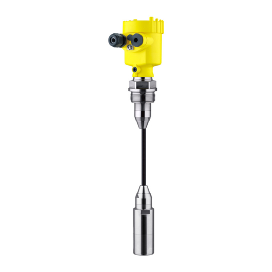
Page 7: Product Description
PLICSCOM" (optional) – Supplementary instructions manual 31708 "Heating for display and adjustment module" (optional) – Supplementary instructions manual "Plug connector for con- tinuously measuring sensors" (optional) – Ex-specific "Safety instructions" (with Ex versions) – if necessary, further certificates VEGABAR 66 with suspension cable consists of the following com- Constituent parts ponents: • Transmitter • Suspension cable •... - Page 8 3 Product description Fig. 1: Example of a VEGABAR 66 with suspension cable (left) and connection tube (right) Housing with integrated electronics Suspension cable Connection tube Threaded fitting Transmitter Protective cap The nameplate contains the most important data for identification and Type plate use of the instrument: VEGABAR 66 • 4 … 20 mA/HART - climate compensated...
-
Page 9: Principle Of Operation
Tools" and "serial number search". In addition to the type label outside, you can also find the serial num- ber on the inside of the instrument. Principle of operation VEGABAR 66 4 … 20 mA/HART - climate compensated is a suspen- Application area sion pressure transmitter for level measurement in wells, basins and atmospherically open vessels under difficult conditions (cold medium and warm humid environment). -
Page 10: Operation
Ascertained transit damage or con- cealed defects must be appropriately dealt with. Storage Up to the time of installation, the packages must be left closed and stored according to the orientation and storage markings on the outside. Unless otherwise indicated, the packages must be stored only under the following conditions: • Not in the open VEGABAR 66 • 4 … 20 mA/HART - climate compensated... -
Page 11: Accessories And Replacement Parts
Electronics module The electronics module is a replacement part for pressure transmitter VEGABAR. One version is available for each type of signal output. You find further information in the operating instructions "Electronics module VEGABAR series 50 and 60 " (Document-ID 30175). VEGABAR 66 • 4 … 20 mA/HART - climate compensated... -
Page 12: Mounting
Fig. 3: Measures against moisture penetration Ventilation and pressure The ventilation of the electronics housing as well as the atmospheric compensation pressure compensation for the measuring cell are realised via a filter element in the area of the cable gland. VEGABAR 66 • 4 … 20 mA/HART - climate compensated... -
Page 13: Mounting Preparations
• Sideways movements of the transmitter can cause measurement errors 1. Therefore, mount VEGABAR 66 in a calm area or in a suitable protective tube • The suspension cable has a capillary for atmospheric pressure compensation 2. - Page 14 4 Mounting Fig. 5: Mounting example: Version with connection tube in an open vessel Fig. 6: Mounting example: Version with suspension cable in a pump shaft VEGABAR 66 • 4 … 20 mA/HART - climate compensated...
-
Page 15: Mounting Steps With Straining Clamp
4. Hold the suspension cable, push the clamping jaws downward and fix them with a light blow Removal is carried out in reverse order. Mounting steps with screwed connection Fig. 8: Threaded fitting Suspension cable Seal screw Cone bushing Seal cone Threaded fitting Seal VEGABAR 66 • 4 … 20 mA/HART - climate compensated... -
Page 16: Mounting Steps With Lock Fitting
Mount VEGABAR 66 with screwed connection as follows: 1. Weld the welded socket into the vessel top 2. Lower VEGABAR 66 to the requested height by means on the welded socket G1½ or 1½ NPT on the vessel side 3. Insert the suspension cable from below into the open screwed connection 4. -
Page 17: Mounting Steps With Housing And Thread
4. Adjust the connection tube of VEGABAR 66 to the requested height and hold it 5. Turn the upper hexagon into the lower hexagon. Spanner width SW 41, torque max. 80 Nm. VEGABAR 66 is now temporarily hold by the washer disc. 6. Tighten fixing screws (2) and (5) with an Allen wrench size 2.5. -
Page 18: Mounting Steps, External Housing
180° to the wall mounting plate. Warning: The four screws of the socket housing must only be hand screwed. A torque > 5 Nm (3.688 lbf ft) can damage the wall mounting plate. VEGABAR 66 • 4 … 20 mA/HART - climate compensated... -
Page 19: Connecting To Power Supply
The data for power supply are specified in chapter "Technical data". Provide a reliable separation between the supply circuit and the mains circuits according to DIN EN 61140 VDE 0140-1. The VEGA power supply units VEGATRENN 149A Ex, VEGASTAB 690 as well as all VEGAMETs and VEGASCANs meet this requirement. -
Page 20: Connection Procedure
5. Insert the cable into the sensor through the cable entry 6. Lift the opening levers of the terminals with a screwdriver (see following illustration) 7. Insert the wire ends into the open terminals according to the wir- ing plan VEGABAR 66 • 4 … 20 mA/HART - climate compensated... - Page 21 IP 68 version with exter- Proceed as follows: nal housing 1. Loosen the four screws on the housing base with an Allen key size 4 2. Remove the mounting plate from the housing socket VEGABAR 66 • 4 … 20 mA/HART - climate compensated...
-
Page 22: Wiring Plan, Single Chamber Housing
5 cm of the cable mantle, strip approx. 1 cm insulation from the ends of the individual wires. After shortening the cable, fasten the type plate with support back onto the cable. VEGABAR 66 • 4 … 20 mA/HART - climate compensated... -
Page 23: Wiring Plan, Double Chamber Housing
Voltage supply, signal output Wiring plan, double chamber housing The following illustration apply to non-Ex as well as Ex ia versions. The Exd version is described in the next subchapter. VEGABAR 66 • 4 … 20 mA/HART - climate compensated... - Page 24 Connection compartment I 2 C Fig. 17: Connection compartment, double chamber housing Spring-loaded terminals for voltage supply Plug connector for VEGACONNECT (I²C interface) Ground terminal for connection of the cable screen VEGABAR 66 • 4 … 20 mA/HART - climate compensated...
-
Page 25: Wiring Plan, Double Chamber Housing Ex D
I 2 C 5 6 7 8 Fig. 19: Electronics compartment, double chamber housing Plug connector for VEGACONNECT (I²C interface) Internal connection cable to the connection compartment Terminals for VEGADIS 61 VEGABAR 66 • 4 … 20 mA/HART - climate compensated... -
Page 26: Wiring Plan - Version Ip 66/Ip 68, 1 Bar
Wiring plan - version IP 66/IP 68, 1 bar Wire assignment, con- nection cable Fig. 22: Wire assignment, connection cable brown (+) and blue (-) to power supply or to the processing system Shielding VEGABAR 66 • 4 … 20 mA/HART - climate compensated... -
Page 27: Wiring Plan, External Housing With Version Ip 68
5 Connecting to power supply Wiring plan, external housing with version IP 68 Overview Fig. 23: VEGABAR 66 in IP 68 version 25 bar, non-Ex and axial cable outlet, external housing VEGABAR 66 • 4 … 20 mA/HART - climate compensated... - Page 28 Spring-loaded terminals for voltage supply Ground terminal for connection of the cable screen Cable gland to the process component Spring-loaded terminals for connection of the external indication VEGADIS Plug connector for VEGACONNECT (I²C interface) VEGABAR 66 • 4 … 20 mA/HART - climate compensated...
-
Page 29: Switch-On Phase
Fig. 26: Wiring plan external electronics Voltage supply Switch-on phase Switch-on phase After connecting VEGABAR 66 to power supply or after a voltage recurrence, the instrument carries out a self-check for approx. 30 seconds: • Internal check of the electronics •... - Page 30 5 Connecting to power supply Then the corresponding current is outputted to the cable (the value corresponds to the actual level as well as the settings already carried out, e.g. factory setting). VEGABAR 66 • 4 … 20 mA/HART - climate compensated...
-
Page 31: Set Up With The Display And Adjustment Module Plicscom
4. Screw housing cover with inspection window tightly back on Removal is carried out in reverse order. The display and adjustment module is powered by the sensor, an ad- ditional connection is not necessary. VEGABAR 66 • 4 … 20 mA/HART - climate compensated... -
Page 32: Adjustment System
Fig. 28: Display and adjustment elements LC display Indication of the menu item number Adjustment keys • Key functions [OK] key: – Move to the menu overview – Confirm selected menu – Edit parameter VEGABAR 66 • 4 … 20 mA/HART - climate compensated... -
Page 33: Setup Steps
HART mode Standard Address 0 Level or process pres- VEGABAR 66 can be used for level as well as for process pressure sure measurement measurement. Default setting is level measurement. The mode can be changed in the adjustment menu. Depending on the application only the respective subchapter "Level or process pressure measurement" is of importance. There, you find... - Page 34 "Units of measurement" will be displayed. 3. Activate the selection with [OK] and select the requested unit with [->] (in the example m). Selection options: mbar, bar, psi, Pa, kPa, MPa, inHg, mmHg, inH VEGABAR 66 • 4 … 20 mA/HART - climate compensated...
- Page 35 Min. adjustment +000.0 % +0000.0 mbar 0000.0 mbar 2. Set the requested percentage value with [+] and [->]. 3. Confirm with [OK] and edit the requested mbar value. Selection options: °C, °F. VEGABAR 66 • 4 … 20 mA/HART - climate compensated...
- Page 36 3. Carry out a position correction 4. Carrying out zero adjustment 5. Carry out span adjustment In the menu item "Adjustment unit" you select the physical unit in which the adjustment should be carried out, e.g. mbar, bar, psi… The position correction compensates the influence of the mounting position or static pressure on the measurement. It does not influence the adjustment values. VEGABAR 66 • 4 … 20 mA/HART - climate compensated...
- Page 37 1. Push the [OK] button in the measured value display, the menu overview is displayed. ▶ Basic adjustment Display Diagnostics Service Info 2. Confirm the menu "Basic adjustment" with [OK], the menu item "Unit" will be displayed. Selection options: mbar, bar, psi, Pa, kPa, MPa, inHg, mmHg, inH VEGABAR 66 • 4 … 20 mA/HART - climate compensated...
- Page 38 000.0 % +0000.0 mbar 0000.0 mbar 2. Set the requested mbar value with [+] and [->]. 3. Confirm with [+] and move to span adjustment with [->]. The zero adjustment is finished. Selection options: °C, °F. VEGABAR 66 • 4 … 20 mA/HART - climate compensated...
- Page 39 Linearization curve Linear Enter the requested parameters via the appropriate keys, save your settings and jump to the next menu item with the [->] key. VEGABAR 66 • 4 … 20 mA/HART - climate compensated...
- Page 40 6 Set up with the display and adjustment module PLICSCOM Caution: Note the following if the VEGABAR 66 with corresponding approval is used as part of an overfill protection system according to WHG (Water Resources Act): If a linearization curve is selected, the measuring signal is no longer linearly proportional to the level. This must be taken into consideration by the user, particularly when setting the switching point on the limit signal indicator.
- Page 41 Optional settings Additional adjustment and diagnosis options such as e.g. scaling, simulation or trend curve presentation are shown in the following menu schematic. You will find a detailed description of these menu With instruments with signal output 4 … 20 mA/HART VEGABAR 66 • 4 … 20 mA/HART - climate compensated...
-
Page 42: Menu Schematic
▶ Display Diagnostics Service Info ▼ Displayed value Display unit Scaling Displayed value 0 % = 0.0 ▼ ▼ Scaled Pressure Volume ▼ 100 % = 100.0 Backlight ▼ Switched off VEGABAR 66 • 4 … 20 mA/HART - climate compensated... - Page 43 Deactivated! Address 0 Application ▼ Level Info Basic adjustment Display Diagnostics Service ▶ Info Instrument type Calibration date Last change using PC Sensor characteristics Software version Display now? Serial number VEGABAR 66 • 4 … 20 mA/HART - climate compensated...
-
Page 44: Saving The Parameter Adjustment Data
They are thus available for multiple use or service purposes. If VEGABAR 66 is equipped with a display and adjustment module, the most important data can be read out of the sensor into the display and adjustment module. -
Page 45: Set Up With Pactware And Other Adjustment Programs
I²C connection cable of VEGACONNECT VEGACONNECT USB cable to the PC Necessary components: • VEGABAR 66 • PC with PACTware and suitable VEGA DTM • VEGACONNECT • Power supply unit or processing system VEGABAR 66 • 4 … 20 mA/HART - climate compensated... -
Page 46: Parameter Adjustment With Pactware
PACTware and the VEGA DTMs. Note: Keep in mind that for setup of VEGABAR 66, DTM-Collection in the actual version must be used. All currently available VEGA DTMs are included as a DTM Collection on a CD. -
Page 47: Parameter Adjustment With Ams™ And Pdm
That way they are available for multiple use or service purposes. The VEGA DTM Collection and PACTware in the licensed, profession- al version provide suitable tools for systematic project documentation and storage. VEGABAR 66 • 4 … 20 mA/HART - climate compensated... -
Page 48: Maintenance And Fault Rectification
24 hour service hotline Should these measures not be successful, please call in urgent cases the VEGA service hotline under the phone no. +49 1805 858550. The hotline is available to you 7 days a week round-the-clock. Since we offer this service world-wide, the support is only available in the English language. -
Page 49: Calculation Of Total Deviation (According To Din 16086)
With the analogue signal output there is also the error of the current output F Fault message can also appear if the pressure is higher than the nominal range. VEGABAR 66 • 4 … 20 mA/HART - climate compensated... - Page 50 Total deviation analogue output signal in percent: total perf stab = (0.1 % x 1.4)/year stab = 1.4 % stab = 0.73 % + 1.4 % = 2.13 % total VEGABAR 66 • 4 … 20 mA/HART - climate compensated...
-
Page 51: Exchanging The Electronics Module
The electronics module with serial number includes order- specific data such as factory setting, seal material etc. These are not included in the electronics module without serial number. The serial number is stated on the type label of VEGABAR 66 or on the delivery note. Software update The software version of VEGABAR 66 can be determined as follows: •... -
Page 52: Instrument Repair
Attach the completed form and, if need be, also a safety data sheet outside on the packaging • Please ask the agency serving you for the address of your return shipment. You can find the respective contact data on our website www.vega.com under: "Company - VEGA worldwide" VEGABAR 66 • 4 … 20 mA/HART - climate compensated... -
Page 53: Dismounting
Correct disposal avoids negative effects on humans and the environ- ment and ensures recycling of useful raw materials. Materials: see chapter "Technical data" If you have no way to dispose of the old instrument properly, please contact us concerning return and disposal. VEGABAR 66 • 4 … 20 mA/HART - climate compensated... -
Page 54: Supplement
Ʋ Seal between housing and housing NBR (stainless steel housing), silicone (Alu/plastic hous- cover ing) Ʋ Inspection window in housing cover Polycarbonate (UL-746-C listed) for PLICSCOM Ʋ Ground terminal 316Ti/316L VEGABAR 66 • 4 … 20 mA/HART - climate compensated... - Page 55 10 % Fig. 32: Sudden change of the process variable. t : dead time; t : rise time; t : jump response time Process variable Output signal Depending on the respective instrument and the process fitting, the temperature can deviate from the real process temperature. VEGABAR 66 • 4 … 20 mA/HART - climate compensated...
- Page 56 0 … +10 bar/0 … +1000 kPa +90 bar/+9000 kPa -1 bar/-100 kPa 0 … +25 bar/0 … +2500 kPa +130 bar/+13000 kPa -1 bar/-100 kPa Nominal measuring ranges and overload capability in psig Values less than -1 bar cannot be set. VEGABAR 66 • 4 … 20 mA/HART - climate compensated...
- Page 57 Applies to the digital signal output (HART, Profibus PA, Foundation Fieldbus) as well as to ana- logue current output 4 … 20 mA and refers to the set span. Turn down (TD) is the ratio nominal measuring range/set span. Incl. non-linearity, hysteresis and non-repeatability. VEGABAR 66 • 4 … 20 mA/HART - climate compensated...
- Page 58 0 … 10 bar/0 … 1000 kPa 0 … 150 psig < (0.1 % x TD)/year 0 … 25 bar/0 … 2500 kPa 0 … 350 psig < (0.1 % x TD)/year VEGABAR 66 • 4 … 20 mA/HART - climate compensated...
-
Page 59: Ambient Conditions
< 0.2 mbar/20 Pa (0.003 psig) Limited by the overpressure resistance of the measuring cell. Limitation by the pressure-tightness of the cable connection. Limited by the overpressure resistance of the measuring cell. VEGABAR 66 • 4 … 20 mA/HART - climate compensated... - Page 60 Tested according to the guidelines of German Lloyd, GL directive 2. Tested according to EN 60068-2-27. Depending on the version M12 x 1, according to ISO 4400, Harting, 7/8" FF. VEGABAR 66 • 4 … 20 mA/HART - climate compensated...
- Page 61 Protection rating Ʋ unassembled IP 20 Ʋ mounted into the sensor without cover IP 40 Depending on the version M12 x 1, according to ISO 4400, Harting, 7/8" FF. With this extraction force, the suspension cable can be extracted out of the transmitter. VEGABAR 66 • 4 … 20 mA/HART - climate compensated...
- Page 62 (optionally available) Ʋ External housing IP 65 Overvoltage category Instruments with gauge pressure measuring ranges cannot detect the ambient pressure when submerged, e.g. in water. This can lead to falsification of the measured value. Only with instruments with absolute pressure ranges. VEGABAR 66 • 4 … 20 mA/HART - climate compensated...
-
Page 63: Dimensions
Approvals Instruments with approvals can have different technical data depending on the version. For that reason the associated approval documents of these instruments have to be carefully noted. They are part of the delivery or can be downloaded under www.vega.com via "VEGA Tools" and "serial number search" as well as via "Downloads" and "Approvals". 10.2 Dimensions The following dimensional drawings represent only an extract of the possible versions. Detailed dimensional drawings can be downloaded on www.vega.com under "Downloads" and "Drawings". - Page 64 ø 80 mm ø 77 mm (3.31") (3.15") (3.03") M16x1,5 M20x1,5 M20x1,5/ ½ NPT M20x1,5/ ½ NPT Single chamber version, electropolished Single chamber version, precision casting Double chamber version, precision casting VEGABAR 66 • 4 … 20 mA/HART - climate compensated...
- Page 65 (1.65") 110 mm x 90 mm (4.33" x 3.54") 40mm (1.57") Fig. 41: External housing - Stainless steel version Lateral cable outlet Axial cable outlet Seal 2 mm (0.079 in) VEGABAR 66 • 4 … 20 mA/HART - climate compensated...
- Page 66 Fig. 42: VEGABAR 66, standard version with straining clamp With threaded fitting G1½ (1½ NPT) With thread G1½ (1½ NPT), transmitter with PE plastic coating with direct cable outlet Lock fitting VEGABAR 66 • 4 … 20 mA/HART - climate compensated...
- Page 67 ø 32 mm ") Fig. 43: VEGABAR 66, transmitter 32 mm with straining clamp With threaded fitting G1½ (1½ NPT) With thread G1½ (1½ NPT) with direct cable outlet Lock fitting VEGABAR 66 • 4 … 20 mA/HART - climate compensated...
- Page 68 SW 46 mm ") G1½A / SW 46 mm 1½”NPT ") G1½A / 1½”NPT Fig. 44: VEGABAR 66, PVDF version With threaded fitting G1½ (1½ NPT) With thread G1½ (1½ NPT) VEGABAR 66 • 4 … 20 mA/HART - climate compensated...
- Page 69 " 4xø " 3" " " 4" 10" 8xø " " " " " Fig. 45: VEGABAR 66, flange connection Flanges according to DIN 2501 Flanges according to ANSI B16.5 VEGABAR 66 • 4 … 20 mA/HART - climate compensated...
- Page 70 ø 92 mm (3 ") ø 8 mm ") ø 40 mm ") Fig. 46: VEGABAR 66, hygienic fittings Clamp 2" (ø64 mm) PN16 DIN 32676, ISO 2852/316L Bolting DN 50 VEGABAR 66 • 4 … 20 mA/HART - climate compensated...
- Page 71 Les lignes de produits VEGA sont globalement protégées par des droits de propriété intellec- tuelle. Pour plus d'informations, on pourra se référer au site www.vega.com. VEGA lineas de productos están protegidas por los derechos en el campo de la propiedad indus- trial. Para mayor información revise la pagina web www.vega.com.
- Page 72 HART multidrop 33 – External electronics 29 Hotline 48 – Single chamber housing 23 Installation position 12 Zero adjustment 38 Linearization curve 39 Maintenance 48 Max. adjustment 36 Min. adjustment 35 Moisture 12 Mounting VEGABAR 66 • 4 … 20 mA/HART - climate compensated...
- Page 73 Notes VEGABAR 66 • 4 … 20 mA/HART - climate compensated...
- Page 74 Notes VEGABAR 66 • 4 … 20 mA/HART - climate compensated...
- Page 75 Notes VEGABAR 66 • 4 … 20 mA/HART - climate compensated...
- Page 76 Subject to change without prior notice © VEGA Grieshaber KG, Schiltach/Germany 2013 VEGA Grieshaber KG Phone +49 7836 50-0 Am Hohenstein 113...