Vega VEGABAR 66 Operating Instructions Manual
Submersible pressure transmitter with
certec measuring cell
Hide thumbs
Also See for VEGABAR 66:
- Operating instructions manual (80 pages) ,
- Operating instructions manual (76 pages) ,
- Operating instructions manual (80 pages)

Related Manuals for Vega VEGABAR 66


Summary of Contents for Vega VEGABAR 66
- Page 1 Operating Instructions Submersible pressure transmitter with CERTEC measuring cell ® VEGABAR 66 Foundation Fieldbus Document ID: 36740...
-
Page 2: Table Of Contents
Insert display and adjustment module ................32 Adjustment system ......................33 Setup steps ........................34 Menu schematic ......................42 6.10 Saving the parameter adjustment data ................43 Set up with PACTware and other adjustment programs VEGABAR 66 • Foundation Fieldbus... - Page 3 Disposal ......................... 51 10 Supplement 10.1 Technical data ........................ 52 10.2 Information on Foundation Fieldbus ................60 10.3 Dimensions ........................63 Supplementary documentation Information: Supplementary documents appropriate to the ordered version come with the delivery. You can find them listed in chapter "Product descrip- tion". Editing status:2014-04-24 VEGABAR 66 • Foundation Fieldbus...
-
Page 4: About This Document
Action This arrow indicates a single action. Sequence of actions Numbers set in front indicate successive steps in a procedure. Battery disposal This symbol indicates special information about the disposal of bat- teries and accumulators. VEGABAR 66 • Foundation Fieldbus... -
Page 5: For Your Safety
During work on and with the device the required personal protective equipment must always be worn. Appropriate use Model VEGABAR 66 is a pressure transmitter for level and gauge measurement. You can find detailed information about the area of application in chapter "Product description". Operational reliability is ensured only if the instrument is properly used according to the specifications in the operating instructions manual as well as possible supplementary instructions. -
Page 6: Safety Label On The Instrument
That is why we have introduced an environment management system with the goal of continuously improving company environmental pro- tection. The environment management system is certified according to DIN EN ISO 14001. Please help us fulfill this obligation by observing the environmental instructions in this manual: • Chapter "Packaging, transport and storage" • Chapter "Disposal" VEGABAR 66 • Foundation Fieldbus... -
Page 7: Product Description
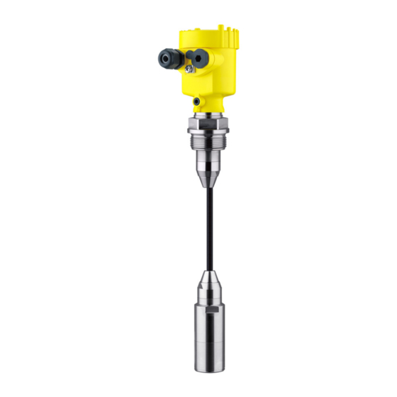
– Operating instructions manual 27835 "Display and adjustment module PLICSCOM" (optional) – Supplementary instructions manual 31708 "Heating for display and adjustment module" (optional) – Supplementary instructions manual "Plug connector for con- tinuously measuring sensors" (optional) Constituent parts VEGABAR 66 with suspension cable consists of the following com- ponents: • Transmitter • Suspension cable •... - Page 8 3 Product description Fig. 1: Example of a VEGABAR 66 with suspension cable (left) and connection tube (right) Housing with integrated electronics Suspension cable Connection tube Threaded fitting Transmitter Protective cap Type label The type label contains the most important data for identification and use of the instrument: VEGABAR 66 • Foundation Fieldbus...
-
Page 9: Principle Of Operation
Principle of operation Application area The VEGABAR 66 is a suspension pressure transmitter for level measurement in wells, basins and atmospherically open vessels. For use in atmospherically closed vessels under vacuum, the instru- ment is available with absolute pressure measuring ranges. -
Page 10: Operation
IEC 61158-2 DD/CFF The DD (Device Descriptions) and CFF (capability files) necessary for planning and configuration of your FF (Foundation Fieldbus) com- munication network are available in the download area of the VEGA homepage www.vega.com under "Services - Downloads - Software - Foundation Fieldbus". The appropriate certificates are also available there. A CD with the appropriate files and certificates can be ordered via e-mail under info@de.vega.com or by phone from one of the VEGA agencies under the order number "DRIVER.S". -
Page 11: Accessories And Replacement Parts
Interface adapter The interface adapter VEGACONNECT 4 enables the connection of communication-capable instruments to the USB interface of a PC. For parameter adjustment of these instruments, an adjustment software such as PACTware with VEGA-DTM is required. You can find further information in the operating instructions "Interface adapter VEGACONNECT" (Document-ID 32628). External display and VEGADIS 61 is suitable for external measured value indication and adjustment unit adjustment of plics®... - Page 12 You will find additional information in the supplementary instructions manual "Protective cover" (Document-ID 34296). The electronics module is a replacement part for pressure transmitter Electronics module VEGABAR. One version is available for each type of signal output. You find further information in the operating instructions "Electronics module VEGABAR series 50 and 60 " (Document-ID 30175). VEGABAR 66 • Foundation Fieldbus...
-
Page 13: Mounting
(e.g. through cleaning processes) or on cooled or heated vessels. Fig. 3: Measures against moisture penetration Ventilation and pressure The ventilation of the electronics housing as well as the atmospheric compensation pressure compensation for the measuring cell are realised via a filter element in the area of the cable gland. VEGABAR 66 • Foundation Fieldbus... -
Page 14: Mounting Preparations
• Sideways movements of the transmitter can cause measurement errors 1. Therefore, mount VEGABAR 66 in a calm area or in a suitable protective tube • The suspension cable has a capillary for atmospheric pressure compensation 2. - Page 15 4 Mounting Fig. 5: Mounting example: Version with connection tube in an open vessel Fig. 6: Mounting example: Version with suspension cable in a pump shaft VEGABAR 66 • Foundation Fieldbus...
-
Page 16: Mounting Steps With Straining Clamp
Suspension cable Suspension opening Clamping jaws Mount VEGABAR 66 with straining clamp as follows: 1. Hang the straining clamp on a suitable wall hook 2. Lower VEGABAR 66 to the requested height 3. Slide the clamping jaws upward and push the suspension cable between them 4. -
Page 17: Mounting Steps With Screwed Connection
Mount VEGABAR 66 with screwed connection as follows: 1. Weld the welded socket into the vessel top 2. Lower VEGABAR 66 to the requested height by means on the welded socket G1½ or 1½ NPT on the vessel side 3. Shift the suspension cable from below through the opened threaded fitting 4. -
Page 18: Mounting Steps With Lock Fitting
4. Adjust the connection tube of VEGABAR 66 to the requested height and hold it 5. Turn the upper hexagon into the lower hexagon. Spanner width SW 41, torque max. 80 Nm. VEGABAR 66 is now temporarily hold by the washer disc. 6. Tighten fixing screws (2) and (5) with an Allen wrench size 2.5. -
Page 19: Mounting Steps With Housing And Thread
Seal Thread Mount into the vessel Mount VEGABAR 66 with housing and thread in the following way: 1. Weld the welded socket G1½ or 1½ NPT to the vessel top 2. Insert the transmitter with connection tube or suspension cable into the opening 3. - Page 20 The socket housing can be displaced by 180° to the wall mounting plate. Warning: The four screws of the socket housing must only be hand screwed. A torque > 5 Nm (3.688 lbf ft) can damage the wall mounting plate. VEGABAR 66 • Foundation Fieldbus...
-
Page 21: Connecting To Power Supply
Connect only in the complete absence of line voltage • If overvoltage surges are expected, overvoltage arresters should be installed according to Foundation Fieldbus specification Tip: We recommend VEGA overvoltage arrester B63-32. In hazardous areas you must take note of the respective regulations, conformity and type approval certificates of the sensors and power supply units. Voltage supply The instrument requires a operating voltage of 9 … 32 V DC. Operat- ing voltage and the digital bus signal are carried on the same two-wire connection cable. -
Page 22: Connection Procedure
10. Connect the screen to the internal ground terminal, connect the outer ground terminal to potential equalisation 11. Tighten the compression nut of the cable entry gland. The seal ring must completely encircle the cable 12. Screw the housing cover back on The electrical connection is finished. VEGABAR 66 • Foundation Fieldbus... - Page 23 1. Loosen the four screws on the housing base with an Allen key size 4 2. Remove the mounting plate from the housing socket Fig. 13: Components of the external housing Screws Wall mounting plate Cable gland VEGABAR 66 • Foundation Fieldbus...
-
Page 24: Wiring Plan, Single Chamber Housing
Remove approx. 5 cm of the cable mantle, strip approx. 1 cm insulation from the ends of the individual wires. After shortening the cable, fasten the type plate with support back on the cable. VEGABAR 66 • Foundation Fieldbus... -
Page 25: Wiring Plan, Double Chamber Housing
Electronics compartment Typ: Display I ² C 5 6 7 8 Fig. 16: Electronics compartment, double chamber housing Simulation switch ("on" = simulation mode) Connection for VEGACONNECT (I²C interface) Internal connection cable to the connection compartment VEGABAR 66 • Foundation Fieldbus... - Page 26 Spring-loaded terminals for voltage supply Plug connector for VEGACONNECT (I²C interface) Ground terminal for connection of the cable screen Wiring plan I 2 C Fig. 18: Wiring plan, double chamber housing Voltage supply, signal output VEGABAR 66 • Foundation Fieldbus...
-
Page 27: Wiring Plan, Double Chamber Housing Ex D
Connection for VEGACONNECT (I²C interface) Internal connection cable to the connection compartment Terminal compartment Fig. 20: Connection compartment, Ex-d-ia double chamber housing Spring-loaded terminals for power supply and cable screen Ground terminal for connection of the cable screen VEGABAR 66 • Foundation Fieldbus... -
Page 28: Wiring Plan - Version Ip 66/Ip 68, 1 Bar
Voltage supply, signal output Wiring plan - version IP 66/IP 68, 1 bar Wire assignment, con- nection cable Fig. 22: Wire assignment, connection cable brown (+) and blue (-) to power supply or to the processing system Shielding VEGABAR 66 • Foundation Fieldbus... -
Page 29: Wiring Plan, External Housing With Version Ip 68
5 Connecting to power supply Wiring plan, external housing with version IP 68 Overview Fig. 23: VEGABAR 66 in IP 68 version 25 bar, non-Ex and axial cable outlet, external housing Electronics and terminal compartment Typ: Display I ² C 5 6 7 8 Fig. - Page 30 Spring-loaded terminals for Foundation Fieldbus connection Simulation switch ("on" = simulation mode) Terminal compartment, housing socket 1 2 3 4 Fig. 25: Connection of the sensor in the housing base Brown Blue Yellow White Shielding Breather capillaries VEGABAR 66 • Foundation Fieldbus...
-
Page 31: Switch-On Phase
Shielding Breather capillaries Switch-on phase Switch-on phase After VEGABAR 66 is connected to voltage supply or after voltage recurrence, the instrument carries out a self-check for approx. 30 seconds. The following steps are carried out: • Internal check of the electronics •... -
Page 32: Set Up With The Display And Adjustment Module Plicscom
4. Screw housing cover with inspection window tightly back on Disassembly is carried out in reverse order. The display and adjustment module is powered by the sensor, an ad- ditional connection is not necessary. VEGABAR 66 • Foundation Fieldbus... -
Page 33: Adjustment System
Adjustment system Fig. 28: Display and adjustment elements LC display Indication of the menu item number Adjustment keys • Key functions [OK] key: VEGABAR 66 • Foundation Fieldbus... -
Page 34: Setup Steps
[OK] will not be saved. Setup steps Level or process pres- VEGABAR 66 can be used for level as well as for process pressure sure measurement measurement. Default setting is level measurement. The mode can be changed in the adjustment menu. - Page 35 3. Activate the selection with [OK] and select the requested unit with [->] (in the example m). 4. Confirm with [OK], the submenu "Density unit" appears. Unit of measurement Density unit ▶ kg/dm³ Selection options: mbar, bar, psi, Pa, kPa, MPa, inHg, mmHg, inH VEGABAR 66 • Foundation Fieldbus...
- Page 36 2. Set the requested percentage value with [+] and [->]. 3. Confirm with [OK] and edit the requested mbar value. 4. Set the requested mbar value with [+] and [->]. 5. Confirm with [+] and move to max. adjustment with [->]. The min. adjustment is finished. Selection options: °C, °F. VEGABAR 66 • Foundation Fieldbus...
- Page 37 If the adjustment ranges are exceeded, the message "Outside param- eter limits" appears. The editing procedure can be aborted with [ESC] or the displayed limit value can be accepted with [OK]. Process pressure measurement Parameter adjustment Set up VEGABAR 66 in the following sequence: "Process pressure meas- 1. Select application "Process pressure measurement" urement" 2. Select the unit of measurement 3. Carry out a position correction 4. Carrying out zero adjustment...
- Page 38 2. Confirm the menu "Basic adjustment" with [OK], the menu item "Unit" will be displayed. Unit Unit of measurement ▼ Temperature unit ▼ °C 3. Activate the selection with [OK] and select "Units of measure- ment with [->]. Selection options: mbar, bar, psi, Pa, kPa, MPa, inHg, mmHg, inH VEGABAR 66 • Foundation Fieldbus...
- Page 39 3. Confirm with [+] and move to span adjustment with [->]. The zero adjustment is finished. Information: The zero adjustment shifts the value of the span adjustment. The span, i.e. the difference between these values, however, remains unchanged. Information: For an adjustment with pressure, simply enter the actual measured value indicated at the bottom of the display. Selection options: °C, °F. VEGABAR 66 • Foundation Fieldbus...
- Page 40 The following safety-relevant data are not read out or written: • • Application Copy sensor data Copy sensor data? Reset The reset function resets all parameters adjusted by the user to the delivery status and the peak values to the actual values. VEGABAR 66 • Foundation Fieldbus...
- Page 41 Optional settings Additional adjustment and diagnosis options such as e.g. scaling, simulation or trend curve presentation are shown in the following menu schematic. You will find a detailed description of these menu items in the operating instructions manual "Display and adjustment module". Special parameters are parameters which are set customer-specifically on the service level with the adjustment software PACTware. VEGABAR 66 • Foundation Fieldbus...
-
Page 42: Menu Schematic
Backlight ▼ AI-Out Switched off Diagnostics Basic adjustment Display ▶ Diagnostics Service Info Peak value indicator Sensor status Trend curve 3.3.1 p-min.: -5.8 mbar p-max.: 167.5 mbar Start trend curve? T-min.: -12.5 °C T-max.: +85.5 °C VEGABAR 66 • Foundation Fieldbus... -
Page 43: Saving The Parameter Adjustment Data
They are thus available for multiple use or service purposes. If VEGABAR 66 is equipped with a display and adjustment module, the most important data can be read out of the sensor into the display and adjustment module. -
Page 44: Set Up With Pactware And Other Adjustment Programs
Fig. 30: Connection via VEGACONNECT externally I²C bus (com.) interface on the sensor I²C connection cable of VEGACONNECT VEGACONNECT USB cable to the PC Necessary components: • VEGABAR 66 • PC with PACTware and suitable VEGA DTM VEGABAR 66 • Foundation Fieldbus... -
Page 45: Parameter Adjustment With Pactware
PACTware and the VEGA DTMs. Note: Keep in mind that for setup of VEGABAR 66, DTM-Collection in the actual version must be used. All currently available VEGA DTMs are included as a DTM Collection on a CD. -
Page 46: Maintenance And Fault Rectification
24 hour service hotline Should these measures not be successful, please call in urgent cases the VEGA service hotline under the phone no. +49 1805 858550. The hotline is manned 7 days a week round-the-clock. Since we offer this service worldwide, the support is only available in the English language. The service is free, only standard call charges are incurred. -
Page 47: Calculation Of Total Deviation (According To Din 16086)
: Long-term drift • stab : Temperature coefficient (influence of medium or ambient temperature) • : Deviation • : Error current output Example Level measurement 1500 mmWs Fault message can also appear if the pressure is higher than the nominal range. VEGABAR 66 • Foundation Fieldbus... -
Page 48: Exchanging The Electronics Module
8 Maintenance and fault rectification Product temperature 40 °C, reference temperature 20 °C VEGABAR 66 with measuring range 0.2 bar Deviation < 0.1 % Calculation ΔT: ΔT = 40 °C - 20 °C = 20 K Calculation of the set Turn Down: TD = 200 mbar/147 mbar, TD = 1.4 Basic accuracy digital output signal in percent: = √((F... -
Page 49: Software Update
The electronics module with serial number includes order- specific data such as factory setting, seal material etc. These are not included in the electronics module without serial number. The serial number is stated on the type label of VEGABAR 66 or on the delivery note. Software update The software version of VEGABAR 66 can be determined as follows: •... -
Page 50: How To Proceed If A Repair Is Needed
Clean the instrument and pack it damage-proof • Attach the completed form and, if need be, also a safety data sheet outside on the packaging • Please contact the agency serving you to get the address for the return shipment. You can find the agency on our home page www.vega.com. VEGABAR 66 • Foundation Fieldbus... -
Page 51: Dismount
These may be used only for privately used products according to the WEEE directive. Correct disposal avoids negative effects on humans and the environ- ment and ensures recycling of useful raw materials. Materials: see chapter "Technical data" If you have no way to dispose of the old instrument properly, please contact us concerning return and disposal. VEGABAR 66 • Foundation Fieldbus... -
Page 52: Supplement
Ʋ Seal between housing socket and wall TPE (fixed connected) mounting plate Ʋ Seal between housing and housing NBR (stainless steel housing), silicone (Alu/plastic hous- cover ing) Ʋ Inspection window in housing cover Polycarbonate (UL-746-C listed) for PLICSCOM Ʋ Ground terminal 316Ti/316L VEGABAR 66 • Foundation Fieldbus... - Page 53 (-58 … +32 °F) and +100 … +150 °C (+212 … +302 °F) Input variable Adjustment Adjustment range of the min./max. adjustment relating to the nominal measuring range: Ʋ Percentage value -10 … 110 % Ʋ Pressure value -20 … 120 % VEGABAR 66 • Foundation Fieldbus...
- Page 54 +500 psig -15 psig 0 … +35 psig +700 psig -15 psig 0 … +70 psig +950 psig -15 psig 0 … +150 psig +1300 psig -15 psig Values less than -1 bar cannot be set. VEGABAR 66 • Foundation Fieldbus...
- Page 55 < 0.05 %/10 K x TD ture range Thermal change, current output Applies also to the analogue 4 … 20 mA current output and refers to the set span. Incl. non-linearity, hysteresis and non-repeatability. VEGABAR 66 • Foundation Fieldbus...
- Page 56 PN 16 or PN 40 Ʋ Flange GFK 10 bar Limited by the overpressure resistance of the measuring cell. Limitation by the pressure-tightness of the cable connection. Limited by the overpressure resistance of the measuring cell. VEGABAR 66 • Foundation Fieldbus...
- Page 57 – 1 x closing cap ½ NPT, 1 x blind plug ½ NPT – 1 x plug (depending on the version), 1 x blind stopper M20 x 1.5 – 2 x blind plug M20 x 1,5 Tested according to the guidelines of German Lloyd, GL directive 2. Tested according to EN 60068-2-27. Depending on the version M12 x 1, according to ISO 4400, Harting, 7/8" FF. VEGABAR 66 • Foundation Fieldbus...
- Page 58 Ʋ Max. length 1000 m (3281 ft) Ʋ Min. bending radius at 25 °C/77 °F 25 mm (0.985 in) Ʋ Diameter approx. 8 mm (0.315 in) Ʋ Colour - Non-Ex version Black Ʋ Colour - Ex-version Blue VEGABAR 66 • Foundation Fieldbus...
- Page 59 Voltage supply Operating voltage Ʋ Non-Ex instrument 9 … 32 V DC Ʋ Ex-ia instrument 9 … 24 V DC Depending on the version M12 x 1, according to ISO 4400, Harting, 7/8" FF. With this extraction force, the suspension cable can be extracted out of the transmitter. VEGABAR 66 • Foundation Fieldbus...
-
Page 60: Information On Foundation Fieldbus
Approvals Instruments with approvals can have different technical specifications depending on the version. For that reason the associated approval documents of these instruments have to be carefully noted. They are part of the delivery or can be downloaded under www.vega.com via "VEGA Tools" and "Instrument search" as well as via "Downloads" and "Approvals". 10.2 Information on Foundation Fieldbus Block diagram, measured value processing The following illustration shows the Transducer Block and Function block in simplified form. - Page 61 Channel = 2: Secondary Value 1 Channel = 3: Secondary Value 2 AI 3 Channel = 4: Temperature Fig. 32: Transducer Block VEGABAR 66 TB Transducer Block Function Block (AI =Analogue Input) Diagram, adjustment The following illustration shows the function of the adjustment:...
- Page 62 – 0: "non-specific" • display_source_selector – Selects the type of value that is displayed on the indication-/adjustement-module – "0: ""Physical value"" 1: ""Percent value"" 2: ""Lin percent value"" 6: ""Out(AI1)"" 7: ""Level"" 8: ""Out(AI2)"" 9: ""Out(AI3)""" • max_peak_sensor_value – Holds the maximum sensor value. Write access resets to current value. Unit derives from 'Sen- sor_range.unit' – Write access resets to current value • min_peak_sensor_value – Holds the minimum sensor value. Write access resets to current value. Unit derives from 'Sen- sor_range.unit' VEGABAR 66 • Foundation Fieldbus...
-
Page 63: Dimensions
• min_peak_temperature_value – Holds the minimum process temperature. Write access resets to current value. Unit derives from 'Temperature.unit' – Write access resets to current value 10.3 Dimensions The following dimensional drawings represent only an extract of the possible versions. Detailed dimensional drawings can be downloaded at www.vega.com under "Downloads" and "Drawings". VEGABAR 66 • Foundation Fieldbus... - Page 64 Aluminium housing in protection rating IP 66/IP 68, 1 bar ~ 105 mm ~ 150 mm (4.13") (5.91") ø 86 mm ø 86 mm (3.39") (3.39") M16x1,5 M20x1,5 M20x1,5 M20x1,5/ ½ NPT Single chamber version Double chamber version VEGABAR 66 • Foundation Fieldbus...
- Page 65 (4.06") ø 86 mm ø 80 mm ø 79 mm (3.39") (3.15") (3.11") M16x1,5 M20x1,5 M20x1,5/ ½ NPT M20x1,5/ ½ NPT Single chamber version, electropolished Single chamber version, precision casting Double chamber version, precision casting VEGABAR 66 • Foundation Fieldbus...
- Page 66 (4.33" x 3.54") 41,6 mm (1.64") ~ 66 mm (2.60") 110 mm x 90 mm (4.33" x 3.54") Fig. 39: IP 68 version with external housing - plastic version Lateral cable outlet Axial cable outlet VEGABAR 66 • Foundation Fieldbus...
- Page 67 10 Supplement 68 mm (2.68") 42mm (1.65") 110 mm x 90 mm (4.33" x 3.54") 40mm (1.57") Fig. 40: External housing - Stainless steel version Lateral cable outlet Axial cable outlet Seal 2 mm (0.079 in) VEGABAR 66 • Foundation Fieldbus...
- Page 68 ") ø 44 mm ø 40 mm ") ") Fig. 41: VEGABAR 66, standard version with straining clamp With threaded fitting G1½ (1½ NPT) With thread G1½ (1½ NPT), transmitter with PE plastic coating with direct cable outlet Lock fitting...
- Page 69 ø 8 mm ø 21,3 mm ") ") ø 32 mm ") Fig. 42: VEGABAR 66, transmitter 32 mm with straining clamp With threaded fitting G1½ (1½ NPT) With thread G1½ (1½ NPT) with direct cable outlet Lock fitting VEGABAR 66 • Foundation Fieldbus...
- Page 70 10 Supplement VEGABAR 66, PVDF version SW 46 mm ") G1½A / SW 46 mm 1½”NPT ") G1½A / 1½”NPT Fig. 43: VEGABAR 66, PVDF version With threaded fitting G1½ (1½ NPT) With thread G1½ (1½ NPT) VEGABAR 66 • Foundation Fieldbus...
- Page 71 4xø " " " " 4xø 3" " " " " 4" 10" 8xø " " " " " Fig. 44: VEGABAR 66, flange connection Flanges according to DIN 2501 Flanges according to ANSI B16.5 VEGABAR 66 • Foundation Fieldbus...
- Page 72 ø 78 mm (3 ") ") ø 92 mm (3 ") ø 8 mm ") ø 40 mm ") Fig. 45: VEGABAR 66, hygienic fittings Clamp 2" (ø64 mm) PN16 DIN 32676, ISO 2852/316L Slotted nut DN 50 VEGABAR 66 • Foundation Fieldbus...
- Page 73 Les lignes de produits VEGA sont globalement protégées par des droits de propriété intellec- tuelle. Pour plus d'informations, on pourra se référer au site www.vega.com. VEGA lineas de productos están protegidas por los derechos en el campo de la propiedad indus- trial. Para mayor información revise la pagina web www.vega.com.
- Page 74 Max. adjustment 37 Min. adjustment 36 Moisture 13 Mounting – in the basin 19 – in the vessel 19 Mounting external housing 19 Position correction 36, 39 Pressure compensation 13 Process conditions 13 Recycling 51 VEGABAR 66 • Foundation Fieldbus...
- Page 75 Notes VEGABAR 66 • Foundation Fieldbus...
- Page 76 Subject to change without prior notice © VEGA Grieshaber KG, Schiltach/Germany 2014 VEGA Grieshaber KG Phone +49 7836 50-0 Am Hohenstein 113...
Need help?
Do you have a question about the VEGABAR 66 and is the answer not in the manual?
Questions and answers