
Related Manuals for Viavi 8000 V2 Platform


Summary of Contents for Viavi 8000 V2 Platform
- Page 1 8000 V2 Platform Scalable Test Platform designed for installation, commissioning, maintenance and troubleshooting of fiber networks User Manual...
- Page 3 8000 V2 Platform Scalable Test Platform designed for installation, commissioning, maintenance and troubleshooting of fiber networks User Manual Viavi Solutions 1-844-GO-VIAVI www.viavisolutions.com...
- Page 5 In the European Union, all equipment purchased from Viavi after 2005-08-13 can be returned for disposal at the end of its useful life. Viavi will ensure that all waste equipment returned is reused,...
- Page 6 Instructions for returning waste equipment to Viavi can be found in the Environmental section of Viavi’s web site at www.viavisolutions.com. If you have questions concerning disposal of your equipment, contact Viavi’s WEEE Program Management team at...
-
Page 7: Table Of Contents
......2 About the 8000 V2 Platform ........3 Main features . - Page 8 Defining the regional settings of the system Defining the screen parameters of the 8000 V2 Platform ........26 Backlight .
- Page 9 Table of Contents ..... . .31 Configuring the power meter ....31 Configuring measurement parameters .
- Page 10 Table of Contents ......47 High Mag. / Low Mag........48 Camera mode .
- Page 11 Establishing connection ...92 Connecting the 8000 V2 Platform and the PC ....92 Configuring the 8000 V2 Platform .
- Page 12 Connection via a local network .107 Accessing the internal memory of the 8000 V2 Platform ......108 Sending files by mail .
- Page 13 ........138 connected Transferring the 8000 V2 Platform interface via WIFI on a PC ....141...
- Page 14 Options and accessories ..158 References of options for the 8000 V2 Platform ......159 References of accessories .
- Page 15 Interpreting alarms Formating the USB memory stick onto the 8000 V2 Platform ......178 Erase disk/harddisk .
- Page 16 Table of Contents Index User Manual 78100000202 Rev. 003...
-
Page 17: About This Guide
About This Guide The 8000 V2 Platform of Viavi provides a handhled modular platform designed for the construction, turn-up and maintenance of fiber networks. The topics discussed in this chapter are as follows: – “Purpose and scope” on page xviii –... -
Page 18: Purpose And Scope
Assumptions This guide is intended for novice, intermediate, and experienced users who want to use the 8000 V2 Platform effectively and efficiently. We are assuming that you have basic computer and mouse/track ball experience and are familiar with basic telecommunication concepts and terminology. - Page 19 About This Guide Conventions Table 1 Typographical conventions (Continued) Description Example Text you must type exactly as Type: in the dia- a:\set.exe shown appears in this log box type- face. Variables appear in this type- Type the new hostname face. Book references appear in this Refer to Newton’s Telecom typeface.
- Page 20 About This Guide Conventions This symbol represents a risk of electrical shock. NOTE This symbol represents a Note indicating related information or tip. This symbol, located on the equipment or its packaging indicates that the equipment must not be disposed of in a land- fill site or as municipal waste, and should be disposed of according to your national regulations.
-
Page 21: 8000 V2 Platform Overview
8000 V2 Platform Overview Chapter 1 This chapter provides a general description of the 8000 V2 Platform. Topics discussed in this chapter include the following: – “Unpacking the instrument” on page 2 – “About the 8000 V2 Platform” on page 2 –... -
Page 22: Unpacking The Instrument
Chapter 1 8000 V2 Platform Overview Unpacking the instrument Unpacking the instrument 1 Remove the 8000 V2 Platform and its accessories from the packing case. 2 Check that the module and accessories ordered are all there. If any part is missing or damaged please contact your local Viavi agent. -
Page 23: Main Features
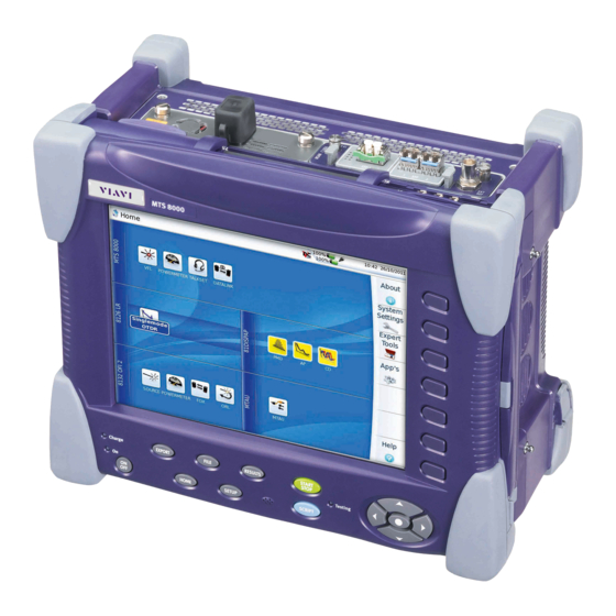
Main features Modules and plug-in units are easily interchangeable in the field, reducing the number of instruments to be carried. The 8000 V2 Platform employs multi-tasking for the simultaneous perfor- mance of several operations: – acquisitions – modifications of parameters –... - Page 24 Chapter 1 8000 V2 Platform Overview Main features – Remote the screen of the 8000 V2 Platform onto a PC and issue commands from the keyboard of the PC – ... Fig. 2 MTS/T-BERD 8000 V2 with modules & Battery pack 10.4’’...
-
Page 25: Hard Keys And Indicators
This button is used to enter a sequence of commands and execute it NOTE All these functions, except , depend on the modules used and the measurements made: refer to the user manuals of the corre- sponding modules of the 8000 V2 Platform. User Manual 78100000202 Rev. 003... -
Page 26: Front Panel Indicators
Front panel The 8000 V2 Platform is equipped with three indicators, lit into a different color according to the status of the equipment. indicators Table 6... -
Page 27: Safety Information
Safety information Chapter 2 This chapter gives the main information on the safety conditions when using the 8000 V2 Platform: – “Battery and AC/DC safety information” on page 8 – “Precautions relating to optical connections” on page 8 – “Laser Safety instructions” on page 9 User Manual 78100000202 Rev. -
Page 28: Battery And Ac/Dc Safety Information
If another adapter or battery is used, it may damage the 8000 V2 Plat- form itself. Using the 8000 V2 Platform with a battery other than the one supplied by the manufacturer of the 8000 V2 Platform may entail risks of fire or explo- sion. -
Page 29: Laser Safety Instructions
The optical connectors must therefore be clean and dust-free. If the optical connection is not being used, protect the connections of 8000 V2 Platform using the protective caps. Laser Safety instructions The provisions contained in two standards define the safety procedures... - Page 30 Chapter 2 Safety information Laser Safety instructions User Manual 78100000202 Rev. 003...
-
Page 31: Starting Up
“Fitting and removing a module carrier or a module” on page 12 – “Choosing the position of the instrument and fitting the carrying handle/strap” on page 17 – “Charging the battery” on page 19 – “Switching the 8000 V2 Platform on and off” on page 21 User Manual 78100000202 Rev. 003... -
Page 32: Fitting And Removing A Module Carrier Or A Module
Fitting and removing a module carrier or a module Fitting and removing a module carrier or a module The 8000 V2 Platform must be switched off, and if it is operating on the mains, its supply cable must be unplugged. -
Page 33: Fitting A Module
Chapter 3 Starting up Fitting and removing a module carrier or a module Torque wrench (optional) If you want to ensure that you don’t apply too much pressure when connecting or disconnecting modules, you can optionally use a torque wrench capable of applying 1.5 N-m (13.3 in-lb). A torque wrench with the ability to apply up to 20 in-lb in 0.1 in-lb increments will be adequate. - Page 34 Chapter 3 Starting up Fitting and removing a module carrier or a module Base Unit Mating Connector Fig. 7 Base Unit Mating Connector Module Mating Connector Fig. 8 Module Mating Connector To align the connectors properly: Position the Module over the base unit, with the Module’s mating connector directly over the mating connector on the base unit.
- Page 35 Chapter 3 Starting up Fitting and removing a module carrier or a module Module or Module Carrier align align parallel position Base Unit Fig. 9 Proper alignment of Module and Base Unit Slowly lower the Module until it is just over the holes on the base unit, and then gently but firmly press the center of the module to attach it to the base unit.
-
Page 36: Removing The Module
Chapter 3 Starting up Fitting and removing a module carrier or a module After the Module is secured to the base unit, put the hex key back in the groove in the Battery Module, and then do the following: Position the battery module over the Module, with the battery module’s mating connector directly over the mating connector on the Module. -
Page 37: Choosing The Position Of The Instrument And Fitting The Carrying Handle/Strap
Choosing the position of the instrument and fitting the carrying handle/strap Setting the Depending on the conditions of use of the 8000 V2 Platform, the instru- ment may be placed on a flat surface or held in the hand. standard stand User Manual 78100000202 Rev. -
Page 38: Installing The Kickstand (Option)
To change the stand from “seated user” position to “standing user” posi- tion, press both sides to slide the stand towards the upper end of its groove. Installing the A kickstand may be installed on the 8000 V2 Platform, if the option has been ordered with the equipment. kickstand (option) –... -
Page 39: Charging The Battery
Chapter 3 Starting up Charging the battery – To fit a strap (or a handle), position each stud against the attach- ment point provided for the purpose on the sides of the cover, and press. – To detach the strap (or handle) from the instrument, lift the stud away from its attachment to open the internal clip, and pull. -
Page 40: Charging The Battery
Example: level display When two batteries are set in the battery pack of the 8000 V2 Platform, both battery icons are displayed on the upper banner, each one with its charge level. Example:... -
Page 41: Switching The 8000 V2 Platform On And Off
Next time the key is pressed, they are recalled. Resetting the If the 8000 V2 Platform freezes, prolonged pressure (about 4 s.) on the key will reset the instrument 8000 V2 Platform User Manual... - Page 42 Chapter 3 Starting up Switching the 8000 V2 Platform on and off User Manual 78100000202 Rev. 003...
-
Page 43: Configuring The 8000 V2 Platform
– “Defining the screen parameters of the 8000 V2 Platform” on page 26 – “Defining the Audio parameters of the 8000 V2 Platform” on page 27 – “Defining the Automatic shutdown of the 8000 V2 Platform” on page 28 User Manual... -
Page 44: Displaying The System Settings Screen
Chapter 4 Configuring the 8000 V2 Platform Displaying the System Settings screen Displaying the System Settings screen To display the System Settings screen, you must: Press the H hard key to reach the Home page. Fig. 15 Home page Press the menu key System Settings to open the System Settings screen. -
Page 45: Defining The Regional Settings Of The System
Defining the regional settings of the system Defining the regional settings of the system When the 8000 V2 Platform is delivered, it is automatically configured with the System Settings set by default in factory, especially the language and date/time (Language: English / Date format: dd/mm/yyy / Time format: 24 hours clock). -
Page 46: Defining The Screen Parameters Of The 8000 V2 Platform
– Min backlight level: -5 – Max backlight level: +5 If the 8000 V2 Platform is operating on battery, it is advisable to choose a minimum lighting level, acceptable for the user, to keep endurance as long as possible. Contrast... -
Page 47: Screen Saver
Screen Saver Click on Screen Saver if you wish to activate a screen saver to the equip- ment, to extend the life of the battery, in case the 8000 V2 Platform is not used for some time. Instead of the normal screen, a small animated picture of the 8000 V2 Platform is displayed on the blackened screen. -
Page 48: Defining The Automatic Shutdown Of The 8000 V2 Platform
In the Utility box, click on Auto off parameter. Choose a time after which the 8000 V2 Platform will be switched off automatically, if no action has been done for that period: 5, 10 or 30 minutes. Select if the 8000 V2 Platform must not be switched off, even if there is inactivity on the equipment. -
Page 49: Power Meter, Vfl (Visual Fault Locator) & Talkset
Power meter, VFL (Visual Chapter 5 Fault Locator) & Talkset A variety of built-in optical options are available when ordering. See references in Chapter 15 “Options and accessories”, for details. The topics discussed in this chapter are as follows: – “Connection to the power meter, VFL and Talkset”... -
Page 50: Connection To The Power Meter, Vfl And Talkset
«Reference Value» function. Using the Power meter The power meter function is an option chosen at the time of order and incorporated into the 8000 V2 Platform in the factory. To activate the function: Press the button... -
Page 51: Configuring The Power Meter
Chapter 5 Power meter, VFL (Visual Fault Locator) & Talkset Using the Power meter Configuring the power meter Configuring The measurement parameters can be accessed with the key. ETUP measurement parameters Fig. 19 Configuration of power measurement Wavelength Selecting wavelength: - Auto: the wavelength of the input signal will be automatically detected and selected to perform the measurement:... -
Page 52: Configuring The Alarm Parameters Of The Power Meter
Chapter 5 Power meter, VFL (Visual Fault Locator) & Talkset Using the Power meter Attenuator compensation Choice of level to be applied to the wavelength chosen for measurement to compensate for the loss due to the external attenuator (+XX.XX dB). First use the direction keys to choose the wavelength, then press >... -
Page 53: Table Of Results
Chapter 5 Power meter, VFL (Visual Fault Locator) & Talkset Using the Power meter Table of results For one and the same fiber, the power meter displays a table of 9 results corresponding to the different possible wavelengths. The first 4 results are displayed on the screen;... -
Page 54: Performing A Measurement
Chapter 5 Power meter, VFL (Visual Fault Locator) & Talkset Using the Power meter Click on Exit to go back to the Results page. Pressing the Pow. Reference key allows to reach the following function: Standard Reference Selects the current result as reference value to measure the attenuation of a link. -
Page 55: Vfl Function
Chapter 5 Power meter, VFL (Visual Fault Locator) & Talkset VFL Function Fix the plug over the optical input of the power meter so that no light can reach the photodiode of the power meter. If the zero adjustment is made without this plug, an error message may be displayed, as the photodiode will detect too much light. -
Page 56: Storing And Reloading Results
Store trace. Two files are being saved : – The first file is used with the 8000 V2 Platform and allows to retrieve all measurement results. It is saved with the extension «.Lts». – The second file is a ASCII file using tabulations to separate values. -
Page 57: Talkset/Datalink Function
Each end of the optical link must be provided with a 8000 V2 Platform equipped with the Talkset option. NOTE It is possible to use the talkset of the 8000 V2 Platform and to carry out measurements at the same time, on a different fiber. NOTE It is possible to use the Data transfer feature while using the optical telephone of the 8000 V2 Platform. -
Page 58: Establishing Communication
Adjusting The sound is transmitted to the earphones of the headset and, if this function has been activated, to the speaker in the 8000 V2 Platform base. volume level To activate the base loudspeaker and adjust the volume: Press the key. -
Page 59: Disconnection
Headset Volume (from 0 to 100). Disconnection When communication is over, deactivate the Talkset/Datalink function on one of the 8000 V2 Platform. This deactivation can be done by either 8000 V2 Platform. Then, the fiber used for Talkset can be disconnected safely. - Page 60 Chapter 5 Power meter, VFL (Visual Fault Locator) & Talkset Remote screen function via Talkset Your screen is now fully replaced by the distant screen, and every- thing you do on your 8000 V2 Platform is in fact done on the distant 8000 V2 Platform. An icon appears in the top banner of the 8000 V2 Platform.
-
Page 61: Scope
Scope Chapter 6 The scope function is a hot-plug feature enabled directly when inserting a Viavi scope supplied as an accessory (see "References of accesso- ries" page 159). The topics discussed in this chapter are as follows: – "Scope feature" page 42 –... -
Page 62: Scope Feature
P5000/P5000i Scope. Installation of tips The Pass/Fail analysis function on the 8000 V2 Platform can only be used with certain inspection tips mounted on the P5000i. Seven tips, patchcords and bulkheads types, are delivered with the Videoscope Kit (EDFSCOPE5KI) but many others can be used. -
Page 63: Configuring The P5000I Scope
Chapter 6 Scope Configuring the P5000i Scope Configuring the P5000i Scope Scope Plug in your Viavi scope into a USB port from the 8000 V2 Platform. connection Push the button Validate the Scope function Connect probe with the fiber being inspected. -
Page 64: File Parameters
Chapter 6 Scope Configuring the P5000i Scope – MM_: Pass/Fail criteria for multimode connectors from IEC 61300-3- 35 standard. Profiles contain the analysis parameters by which PASS/FAIL criteria are determined. Once the line is selected, you can also add a new profile, clicking on the Add Button (see "Adding a new profile"... -
Page 65: Link Description
Chapter 6 Scope Configuring the P5000i Scope To add a logo to a report generated from test results, select Logo parameter and press right direction key to display the file explorer page and select the image which will be used as logo on the report page (see “Generating a report”... -
Page 66: Adding A New Profile
Chapter 6 Scope Configuring the P5000i Scope Press Exit to return to the Results screen of the scope. Adding a new Once the Setup screen of the scope is displayed, you can add a specific profile which will be used for the test. profile The profile must be created via FiberChek2 , and stored on one... -
Page 67: Starting Up With The Scope
Chapter 6 Scope Starting up with the scope Starting up with the scope Once the FiberScope icon is validated: Press R hard key ESULTS Focus level for image sharpness Fig. 26 Example of the result using the P5000i scope Use the Focus Control button onto the P5000i scope (see Figure 22 on page 42) to adjust the image quality and sharpness. -
Page 68: Camera Mode
Chapter 6 Scope Launching a test of the connector and fiber end-face Camera mode If you are in Freeze mode, or in Mosaic mode, with a picture selected (see “Mosaic Mode” on page 49), press Camera menu key to return to live camera picture. -
Page 69: Overlay
Chapter 6 Scope Launching a test of the connector and fiber end-face A summary of test results is displayed on the right, upper part of the screen. – Zone A: represents the Core zone: it is Zone D the area surrounding the core Zone C –... - Page 70 Chapter 6 Scope Launching a test of the connector and fiber end-face Position 2: Snapshot Menu keys when Live saved on disk : connector picture is selected Selected picture Position 1 : Position 3 : Connector before being cleaned Position 4 : JPEG image Fig.
-
Page 71: Loading A Picture
Press the button. Select Explorer. Select the JPEG file to be loaded via the Explorer. Click on Load. Recognized pictures are images resulting from the Scope option and saved on disk via the 8000 V2 Platform. User Manual 78100000202 Rev. 003... -
Page 72: File Menu
49). File menu Saving the test Once the test has been performed, and the result is displayed on the 8000 V2 Platform screen: result in a jpg file Press F Click on Save key to save a jpg file of the test result on the disk of the 8000 V2 Platform. - Page 73 Chapter 6 Scope File menu On the right menu keys, press Load soft key. In the File Explorer, select the pdf report just created. Press Load. Logo, company & param- eters selected in the Setup page (see “Config- uring the Scope” on page Fig.
- Page 74 Chapter 6 Scope File menu User Manual 78100000202 Rev. 003...
-
Page 75: Applications
(GPL, LGPL, BSB or other). Their purpose is to bring more functionality to the 8000 V2 Plat- form. Viavi doesn’t provide any warranty or support regarding these free software. To access desktop applications, press the button , and the soft key App’s. -
Page 76: Navigation And Text Edition In The Application
Five ways can be used to enter text Enter text using an external keyboard which is connected to the 8000 V2 Platform via the USB port or using an external keyboard of a PC connected to the Platform. Enter text using the keyboard of the Application... -
Page 77: Pdf Viewer
Chapter 7 Applications PDF viewer Fig. 30 Keyboard of the Text Editor Use the arrow keys or the touchscreen to enter the text. Enter manually the text when a touch screen is used. Select Writing on the key Write the letter manually, using the stylus for touch screen You can click on Train, in order to draw each character on its cell. -
Page 78: Web Browser
V2 Platform or of an external keyboard, or by dragging the scroll bars with touchscreen or mouse. Web browser Configuring the Before using the Web Browser onto the 8000 V2 Platform, check/modify the proxy configuration in the System Settings page: Web access On the Home page, press System Settings menu key Select Use proxy parameter in the I/O Interfaces box –... -
Page 79: Opening An Internet Page
Once the Web Browser is displayed, you must enter the internet address. internet page Set the cursor in the address bar: Use the mouse connected via USB port on the 8000 V2 Platform or the mouse of the PC if the screen is deported via VNC appli- cation on the PC. -
Page 80: Navigation Into The Web Browser
Chapter 7 Applications Web browser Fig. 33 Internet page opened with the Web Browser Navigation into Once the Web Browser is open, push the key to display on the right of the screen, the buttons used to navigate. the Web Browser Icon Definition... -
Page 81: Opening A Pdf Document
Chapter 7 Applications Web browser Fig. 34 Creation of bookmarks – Click on to open the page of the bookmark selected in the list – Click on to delete the selected bookmark from the list – Click on to exit the bookmark menu and go back to the Web Browser page. -
Page 82: Text Editor
Quit the application using the Web browser application menu: click on the key Text Editor The Text Editor application allows to enter text on the 8000 V2 Platform and save it into a txt file Text Editor To open the Text editor: page In the Home page, press the App’s key... -
Page 83: Saving The Text In A File
Home page, and keep the application active. Calculator A calculator can be displayed and used onto the 8000 V2 Platform. In the Home page, press the App’s key In the Application screen, select the icon Calculator. -
Page 84: Calendar
Chapter 7 Applications Calendar Fig. 38 Calculator Press to exit the Calculator and go back to the Application page. Press button to go back to the Home page, and keep the Calcu- lator application active. Calendar The Application page also allows to use a calendar, in order to enter Notes, dates, events etc. -
Page 85: Create An Event In The Calendar
Chapter 7 Applications Calendar The page displays by default the calendar for the current date, in the daily mode. The today date corresponds to the date entered in the System Settings page. Create an event Once the Calendar application is active, whatever is the View displayed, you can add events to the calendar. -
Page 86: Create A Category
Chapter 7 Applications Calendar Create a The events saved in the calendar can be defined in a specific category category you can create. To do so: In the Tool Menu, select Category The dialog box opens Enter a name for this category Select a predefined color for this category, or click on to define a new color. - Page 87 Chapter 7 Applications Calendar Fig. 42 Create a new calendar Enter the Calendar Title, which will appear in the View page. You can also give a description of this calendar (for which use it has been created...) You can select a parent of this calendar; another calendar which will be used as model for this one.
-
Page 88: Views Of The Calendar
Chapter 7 Applications Calendar Fig. 43 New calendar in the list Click to Edit the calendar (see Figure 42). Click on to delete the calendar and reassign if necessary the events to another one. Views of the The calendar application allows to display different information on the screen. -
Page 89: Agenda
Chapter 7 Applications Calendar Fig. 44 Example of weekly calendar – : monthly calendar Fig. 45 Example of monthly calendar – : today calendar (same display as a daily calendar) Fig. 46 Example of daily calendar – You can choose the date for which the calendar will be displayed, by using the following fields: Once the date is entered, click on the weekly or monthly icon, to display the calendar for the week/month to which the date belongs. -
Page 90: Event Menu
Chapter 7 Applications Calendar Select Agenda in the View menu Click as many times as necessary on the View key to reach the agenda screen Fig. 47 View Agenda Once selected, you will have to enter the period you want to display on screen For example, in the Figure... -
Page 91: Alarms
Chapter 7 Applications Calendar – Delete: allows to delete the event selected. A confirmation will be asked. – Save: allows to save the event in a .ics format onto the disk of the Platform, or on the usb key connected to the equipment, if any, –... -
Page 92: Sidebar
Chapter 7 Applications Calendar Sidebar A sidebar can be configured, to display more or less information on the calendar screen. Three elements can be displayed on the sidebar: – Calendar: this displays a calendar of the month activated. – Calendar Selector (displayed by default when application is launched): this display a list of the calendars available, and allows to show or hide the events belonging to the calendar(s) –... -
Page 93: Exiting From The Calendar Application
Chapter 7 Applications Contacts – The sidebar will not be displayed if a monthly calendar is activated. – Click on the white dates to reach the previous or next month (or select a month on the upper toolbar). Calendar selector –... - Page 94 Chapter 7 Applications Contacts Fig. 51 New Contact NOTE You can select the Keyboard or Writing function to enter text (see "Entering text" page 56). If a category is modified / added / deleted via the eMail application, it will be automatically added / deleted in the Calendar application, and vice versa..
- Page 95 Chapter 7 Applications Contacts Fig. 52 New contact NOTE When a contact belongs to a category, a circle with the colour corre- sponding to the category is displayed next to its name. 10 You can use the menu Categories at the bottom of the screen to filter the contacts according to the category they belong to.
-
Page 96: Email Application
Fig. 53 eMail: Folder List page Configuring an In order to be able to send and receive e-mail onto the 8000 V2 Platform, you must first create and configure the user account. e-mail account Once the Index page is displayed, click on one the Basic parameter... -
Page 97: Basic Parameters
Chapter 7 Applications eMail Application Fig. 54 Account page Click on New button to create a new account (or on Edit if an existing account must be modified). The Page Index displays Basic parameters Click on Basic line to display the Basic screen and enter general information on the account. - Page 98 Chapter 7 Applications eMail Application – IMAP4: Internet Message Access Protocol – News (NNTP): Network News Transfer Protocol – Local mbox file – None (SMTP only): Simple Mail Transfer Protocol CAUTION Once the Protocol is selected, and the Apply key is pressed, if you go back to the Basic page, you cannot modify the Protocol previously defined.
-
Page 99: Receive Parameters
Chapter 7 Applications eMail Application – SMTP server (send): use this protocol in order to exclusively send mails and not to receive them. Once the Basic Page is completed, click on to validate this PPLY account. Receive In the page index, click on Receive and define the parameters for parameters the received messages. -
Page 100: Send Parameters
Chapter 7 Applications eMail Application – Show subscribed folders only – Bandwidth-efficient mode (prevents retrieving remote tags): NEWS (NNTP) – Maximum number of articles to download: Local Mbox file – Default inbox The following three parameters are available for all protocols: –... -
Page 101: Compose Parameters
Chapter 7 Applications eMail Application Once selected, you can choose the authentication method to be used: Automatic / PLAIN / LOGIN / CRAM-MD5 You can also enter a User ID and Password for authentification when sending messages. NOTE If those two fields are empty, the same user ID and password as the Receive parameters will be used. -
Page 102: Advanced Parameters
Chapter 7 Applications eMail Application Fig. 59 Mail Account - Template parameters The page allows to enter a text which can be used as template for the messages composed / replied / forwarded (select the correct tab). – Select Use template when composing new messages in order to automatically get the message from the template into the messages sent / replied / forwarded. -
Page 103: Sending An E-Mail
: Click on Close to close the account page and reach the E-mail page. Sending an e- Once the account has been correctly configured. you can send e-mail using the 8000 V2 Platform. mail In the account page, select the account to be used for sending message (icon... - Page 104 Chapter 7 Applications eMail Application In the Folder list, click on Address Book and select the contact to which an e-mail must be sent, and click on the Email button (see Figure 52); or directly click on the contact e-mail address. The screen displays a page to compose e-mail, in which the sender address is the one corresponding to the account previously selected.
-
Page 105: Exiting From The Email Application
Chapter 7 Applications File Explorer Fig. 63 Folder «Inbox» open On this screen you can also: – : Click to refresh the display and display the mail recently received. – : Click to reply to the message sender. – : Click to transfer the message to other recipients. –... - Page 106 Chapter 7 Applications File Explorer User Manual 78100000202 Rev.003...
-
Page 107: Stratasync
Stratasync Chapter 8 This chapter describes how to synchronize your 8000 V2 Platform to the Stratasync application. The topics discussed in this chapter are as follows: – "Principle and prerequisites of the Stratasync" page 88 – "Configuring and synchronizing the 8000 V2 Platform" page 89 User Manual 78100000202 Rev.003... -
Page 108: Principle And Prerequisites Of The Stratasync
The user must have subscribed to Stratasync, and by consequence, he must have acquired an account Identifier and a password. The Ethernet and Proxy parameters must have been correctly configured in the System Settings page of the 8000 V2 Platform (see “Ethernet > Mode” on page 93 “Proxy >... -
Page 109: Configuring And Synchronizing The 8000 V2 Platform
Chapter 8 Stratasync Configuring and synchronizing the 8000 V2 Platform Configuring and synchronizing the 8000 V2 Platform The 8000 V2 Platform can be configured to be synchronized with the Stratasync. Press System Settings in the Home page Check the configuration of the Ethernet and Proxy parameters. -
Page 110: Connecting The 8000 V2 Platform To Stratasync
Chapter 8 Stratasync Configuring and synchronizing the 8000 V2 Platform Connecting the Once 8000 V2 Platform is configured, in the Home page: 8000 V2 Press Expert Tools > Upgrades menu keys. Platform to Press Stratasync menu key Stratasync The synchronization with Stratasync starts... -
Page 111: Transferring The 8000 V2 Platform Interface
Chapter 9 Platform Interface The 8000 V2 Platform can be used in combination with a PC in order to transfer the Platform Interface onto a PC, or to access the internal memory or USB memory stick contents on the PC. -
Page 112: Establishing Connection
Chapter 9 Transferring the 8000 V2 Platform Interface Establishing connection Establishing connection The connection between 8000 V2 Platform and the PC can be done directly, or via a local network. The transfer of the interface can be done using a VNC window on PC. - Page 113 Enter the current password in the Edition keypad and press Enter to validate. Enter the new password and press Enter to validate. Ethernet > Mode Parameters of the local Ethernet network to which the 8000 V2 Platform is connected: Config 1 to 4 static mode enabling input of the configuration of 4 sites.
-
Page 114: Transferring The Interface
Note the IP Address displayed in the System Settings page. Wait about 10 seconds the connection is established. The 8000 V2 Platform Interface can now be transferred onto the PC, or the internal memory or USB key ocntents can be transferred on PC. -
Page 115: Virtual Control Buttons Bar
Click to install TightVNC software on your PC (not mandatory) Fig. 69 VNC window You can use keyboard mouse of the PC to control the 8000 V2 Platform (see “Equivalence between the keyboard and 8000 V2 Platform” on page 96). -
Page 116: Equivalence Between The Keyboard And 8000 V2 Platform
The virtual control buttons bar is displayed during a few seconds. You may click on any of these buttons to obtain exactly the same results than using the hard keys on the front panel of the 8000 V2 Platform. Equivalence between the keyboard and 8000 V2 Platform... -
Page 117: File Management
File management Chapter 10 The files management with the 8000 V2 Platform can be performed, wether a module is set onto the equipment or not. The topics discussed in this chapter are as follows: – “File Explorer Overview” on page 98 –... -
Page 118: File Explorer Overview
Chapter 10 File management File Explorer Overview File Explorer Overview To reach the File Explorer page – On the Home page, press App’s menu key and select the File Explorer icon. The File Explorer page appears. Fig. 71 File Explorer page Directories and Files selections Directory To select a directory from the explorer page:... -
Page 119: Files Selection
Chapter 10 File management Directories and Files selections Access to Selected directory sub-directory Sub-directory Fig. 72 Directory selection Files selection To select one or several files from the explorer page: Press on files that must be selected. To select a list of files using the keys of the Platform: Select and validate the first file of the list (underlined in red) Set the cursor on the last file of the list (underlined in blue) Maintain the right direction key... -
Page 120: Directories & Files Editing Functions
Chapter 10 File management Directories & Files editing functions Directories & Files editing functions Copy/Cut & To copy (cut) one or several files, or one directory, and paste them in another place: Paste files/ directories Select the directory / the file(s) (see “Directories and Files selec- tions”... -
Page 121: Working With Directories And Files From The Explorer
If different types of files have been selected in the Explorer, only the last one selected will open. File Types For files recognized by the 8000 V2 Platform, the types are symbolized by icons. E.g. Icon Type of FO file OTDR file (.SOR extension) -
Page 122: Sorting Files
JPEG / JPG file (.JPEG extension) PNG file (.PNG extension) XML file (.XML extension) With the 8000 V2 Platform, you can open and load any kind of Fiber Optic files (OTDR, OSA, PON, LTS) even if the corresponding module is not set into the Platform. -
Page 123: Transferring Files To A Pc With A Usb Cable
PC, this can be easily done using the USB cable. with a USB cable Establishing Connect the 8000 V2 Platform to a PC, plugging the USB cable on connection 8000 the mini USB port of the Platform toward a USB port on the PC. V2 Platform <-> PC... -
Page 124: Transferring Files Onto The Pc
Fig. 77 Open 8000 V2 Platform disk content The 8000 V2 Platform disk content opens onto the PC. Transferring files Select the file(s) from the 8000 V2 Platform to be transferred onto onto the PC the PC Fig. 78 Files selection from the 8000 V2 Platform Press Ctrl + C, or right click and select Copy. -
Page 125: Transferring Files To/From A Pc With A Ftp Server
The screen displays the results trace of the active function, or returns to the Home page if no function is active. Remove the mini USB plug from the 8000 V2 Platform USB port. Transferring It is possible, from a PC, to access the internal memory of the 8000 V2... -
Page 126: Connection Via A Local Network
Accessories > Dos Prompt, type ipconfig", then Enter. Note the IP address and the mask of the PC’s sub-network. Plug the RJ 45 connector of the 8000 V2 Platform into a hub or Ethernet switch with a straight-through Ethernet cable (see Figure 79 on page 105). -
Page 127: Accessing The Internal Memory Of The 8000 V2 Platform
On the PC, use an FTP client, and access to internal memory via an internet explorer (I.E, Mozilla Firefox...) or Windows Explorer. In the address bar, type the following address (10.33.16.216, being the IP address of the 8000 V2 Platform defined when the connection was configured; see Figure 81 on page 106): ftp://mts8000:acterna@10.33.16.216/disk/... -
Page 128: Sending Files By Mail
Explorer, select one / several files and click on Copy, then click on Paste on PC to transfer file Sending files by The 8000 V2 Platform can send files (traces or others) via e-mail, from mail the Explorer. Configuring the... -
Page 129: Sending Files From The Explorer
Chapter 10 File management Working with directories and files from the explorer If Sender Mode is set to Auto, any reply to an e-mail sent by the 8000 V2Platform will be lost. Relay Mode Auto or Manual. If the e-mail sending is performed via a SMTP network, select the Manual Relay mode and indicate the SMTP server address in the field Mail Relay, using the edition window. -
Page 130: Creating A Screenshot
Sent. Click on any key to follow. Creating a screenshot You can create captures of what is displayed on the screen, directly from the 8000 V2 Platform. Configuring the To configure the screenshot and choose the format of the generated file:... -
Page 131: Name Of The Screenshots Files
Fig. 85 Example of screenshot, open in the Web Browser of the 8000 V2 Platform Creating a report Once the results page of a function is opened (example: OTDR trace, Power Meter results...), it can be exported in a report, using the 8000 V2 Platform. -
Page 132: Creating The Report
Chapter 10 File management Creating a report On the line File format, select if the report file will be a JPG, PNG or PDF file. To display a Logo on the upper right of the report pages, click on Logo line and select the Logo to be displayed on the upper right of the page: Press to open the edition keypad... -
Page 133: Name Of The Report
The pdf files that can be merged are those generated via the Fast Report key on trace results page or via the E hardkey of the XPORT 8000 V2 Platform (see “Creating a report” on page 111) – The txt files that can be merged are those saved with the results trace (see OTDR Modules User Manual: E8100M02). -
Page 134: Storage Media
“Renaming a directory / file” on page 100). Storage media For saving or recalling data, the 8000 V2 Platform offers a wide choice of media, both built-in and external. Free space on selected media is clearly displayed at the bottom of the left panel. -
Page 135: External Usb Storage Media
250GB (with a minimum of about 100 GB are available for data storage).. External USB The 8000 V2 Platform is equipped with 3 USB ports as standard. One of these can be used to connect an external storage medium, in particular storage media a USB memory stick. -
Page 136: Cloud Storage
Before configuring the Cloud Storage on Platform, you must first create an account on a Cloud Platform on internet. The Cloud storage function onto the 8000 V2 Platform works exclu- sively with sites using the WebDav technology such as CloudSafe (https://secure.cloudsafe.com/pages/index.html) or Box... - Page 137 Fig. 89 Example of configuration Connecting Cloud Storage Once configuration has been established on the 8000 V2 Platform, it is ready to be connected with Cloud server: Select one parameter of the Cloud Storage window on 8000 V2 Platform Press Connect Cloud Storage menu key...
-
Page 138: Transferring Files Using Cloud Storage
Chapter 10 File management Storage media Transferring files Once connection between 8000 V2 Platform and cloud storage server is successfully established, the files can be transferred from one Platform using Cloud to the other. Storage Press H hard key. On the Home page, press App’s and select File Explorer icon. -
Page 139: Abbreviations For Storage Media
Chapter 10 File management Storage media Abbreviations The abbreviations used in the explorer for the different storage media for storage are: media Abbreviation Storage medium disk Internal flash memory harddisk Internal harddisk (option) usbflash USB memory stick cloud-storage Cloud storage media available on PC bluetooth-inbox Bluetooth storage media (option) a. - Page 140 Chapter 10 File management Storage media User Manual 78100000202 Rev. 003...
-
Page 141: Smart Access Anywhere
Smart Access Anywhere. This function allows one distant user, on a PC, to transfer the Platform Interface and work on 8000 V2 Platform or to access the internal memory / USB memory stick contents on the PC and perform files transfer from T-BERD/MTS to PC and vice-versa. -
Page 142: Connection Modes
Ethernet Cable. connection Fig. 91 Ethernet connection The WIFI connection can be used to access to 8000 V2 Platform from any location. This connection is available exclusively if the WIFI option is installed onto the T-BERD/MTS-8000 V2 which will be seen remotely. -
Page 143: Usb/Wifi Connection Through 3G Smartphone
3G WIFI. Smartphone To establish connection between 8000 V2 Platform and Smartphone using USB, connect the USB cable on 8000 V2 Platform and on 3G Smartphone connector. Fig. 93 USB connection through 3G Smartphone To establish connection between 8000 V2 Platform and 3G Smart- phone using WIFI, the WIFI option must be installed onto the 8000 V2 Platform. -
Page 144: Pre-Requisite For Using The Smart Access Anywhere Application
Pre-requisite for using the Smart Access Anywhere Application Pre-requisite for using the Smart Access Anywhere Application To access to a 8000 V2 Platform from any locations, specific require- ments are mandatory: – a licence installed on Platform which will be accessible from any locations. -
Page 145: Launching The Smartaccess Anywhere Application
Chapter 11 Smart Access Anywhere Launching the SmartAccess Anywhere application Enter Access Code (see step 1 on page 126) Fig. 95 Smart Access Anywhere: Connection page If the software version is not the last one available, a message displays, on the upper part of the screen to indicate the latest version available can be downloaded at the address: http://smartaccess.updatemyunit.net. -
Page 146: On The Distant Pc
Chapter 11 Smart Access Anywhere Launching the SmartAccess Anywhere application Fig. 97 Connection to SmartAccessAnywhere Server in progress Once connection is established with the server, the 8000 V2 Plat- form displays a message with the code to be used to access to the equipment remotely. -
Page 147: Using Remote Screen And File Transfer Applications
– transfer files from the equipment toward the PC, and vice-versa. Transferring the To display the remote 8000 V2 Platform onto the PC: interface onto On the Introduction page, click on the PC On the left menu, click on... - Page 148 Click on the upper banner of the 8000 V2 Platform screen to access to the virtual control buttons bar, which allows to emulate hard keys. You may click on any of these buttons to obtain exactly the same results than using the hard keys on the front panel of the 8000 V2 Platform.
- Page 149 Save and quit (Exit) Enter Quit without saving (Abort) Escape a. The Export function is available directly on the 8000 V2 Platform push- ing simultaneously the left and right arrow keys. Transferring To work on files (onto PC and onto unit):...
-
Page 150: Transferring Files
Chapter 11 Smart Access Anywhere Using Remote screen and File Transfer applications Double-click on one directory/storage media to display the contents (directories / sub-directories / files) Navigation buttons Return to the Home directory Select the PC drive in the list click Access to parent directory Transferring files... -
Page 151: Working With Files And Directories On 8000 V2 Platform
Once transfer is completed, the banner disappears and the transferred file is underlined in blue on PC explorer. Working with Renaming file or directory files and Select a file/directory stored on the 8000 V2 Platform hard disk or USB key. directories on Click on 8000 V2... -
Page 152: Modifying Connection Settings
Chapter 11 Smart Access Anywhere Connection information and settings A screen as the following one displays: Fig. 103 Session page This page gives information on connection «in real time». Modifying To modify the settings for connection to internet: connection Press Session menu key on left of the screen settings Disconnect from application pressing On the session screen (see... -
Page 153: Testing Connection
Chapter 11 Smart Access Anywhere Connection information and settings By default, the connection is defined to Smart-guess (default). To modify the current parameters, select Forced settings. The parameters for Port configurations turn automatically active. Modify, if necessary, the port used: Default port (22) is selected by default Select Alternative port (443) if necessary If the parameter Alternative port (443) is selected, you can defined... - Page 154 Chapter 11 Smart Access Anywhere Connection information and settings Once completed, the results for connection display: Fig. 106 Test results The screen displays, in two different tables: – the Upload and Download speed (in Kbyte/s) from Device to server. – the Latency between Device and server (in ms).
-
Page 155: Wifi Option
WIFI Option Chapter 12 The WIFI application is available on option with the 8000 V2 Platform, via a external USB key: ref E60EWIFI. The topics discussed in this chapter are as follows: – "Installation of the WIFI option in the Platform" page 136 –... -
Page 156: Installation Of The Wifi Option In The Platform
Installation of the WIFI option in the Platform The WIFI option is delivered on a USB key to be connected directly to one of the USB port of the 8000 V2 Platform. Plug the WIFI USB key to one of the USB port of the Platform A beep is emitted. -
Page 157: Connection To Ssid
In the AutoConnect parameter, select if the connection to SSID selected must be done automatically (On) or not (Off). Connection to SSID Once configuration is valid, connect the 8000 V2 Platform to the Wireless network: In the Setup screen, press Connect SSID menu key. -
Page 158: Configuring The Wifi Mode To Which The Platform Is Connected
8000 V2 Platform is connected. Dynamic in this mode, which requires a DHCP server, the 8000 V2 Platform requests an IP address from this server which will be allocated dynamically if dynamic host configuration is activated on the local network. - Page 159 Dynamic in this mode, which requires a DHCP server, the 8000 V2 Platform requests an IP address from this server which will be allocated dynamically if dynamic host configuration is activated on the local network.
-
Page 160: Transferring The 8000 V2 Platform Interface Via Wifi On A Pc
Considering 10.33.16.229 is the IP Address of the 8000 V2 Plat- form (as shown Figure 109 on page 139), enter the following address in the Internet Explorer window: http://10.33.16.229:5800 Press Enter to validate. The screen of the 8000 V2 Platform appears offset on your PC. User Manual 78100000202 Rev. 003... -
Page 161: Transferring Files To/From A Pc Via Wifi
On the PC, use an FTP client, and access to internal memory via an internet explorer (I.E, Mozilla Firefox...) or Windows Explorer. In the address bar, type the following address (10.33.16.229 being the IP address of the 8000 V2 Platform defined when the connection was configured): ftp://mts8000:acterna@10.33.16.229/disk/ This allows to access to internal memory. - Page 162 User name: mts8000 – Password: acterna The PC then displays the contents of the internal memory or of the USB memory stick from the 8000 V2 Platform. Internal memory open via Windows Explorer Internal memory open via Internet Explorer Fig. 112...
-
Page 163: Bluetooth Option
Bluetooth option Chapter 13 The Bluetooth interface allows the files transfer or to access the Platform interface remotely. It is an option that must be installed at the factory. The topics discussed in this chapter are as follows: – "Setting up a Bluetooth connection" page 144 –... -
Page 164: Setting Up A Bluetooth Connection
Chapter 13 Bluetooth option Setting up a Bluetooth connection Setting up a Bluetooth connection The Bluetooth option allows file transfers between the 8000 V2 Platform and another device On the Home page, press System Settings key Under I/O interfaces, select Bluetooth > Enable... - Page 165 If the desired device is not displayed on the screen, or if no devices are detected, press the Search Devices soft key. The 8000 V2 Platform is searching for the devices which could be used via Bluetooth with the equipment.
- Page 166 A baragraph is displayed during research Once the research is completed, a list of the available devices is displayed, with the level of detection of the 8000 V2 Platform Fig. 116 List of devices found Using the direction keys...
-
Page 167: Transferring Files Via Bluetooth
Chapter 13 Bluetooth option Transferring files via Bluetooth Transferring files via Bluetooth Once the connection has been established with a bluetooth device: Press the key and then press the System Settings soft key. Use the down arrow or touchscreen to move to the I/O Inter- faces settings and then to File export. -
Page 168: Transferring The Platform Interface On A Laptop Pc Via Bluetooth
Transferring the Platform interface on a laptop PC via Bluetooth If the 8000 V2 Platform is paired with a laptop equipped with Bluetooth, the interface can be transferred on this PC in order to work on the unit from the laptop PC. - Page 169 Bluetooth on PC Click on View Unit button to remote the screen on PC. The current screen of the 8000 V2 Platform displays on a new window on the PC. In the small window next to VNC window (see...
-
Page 170: Removing The Pairing
Chapter 13 Bluetooth option Removing the Pairing In the small window available with the VNC window (see Figure 121 on page 149) click on Stop Viewing button. The VNC window closes. At any time, the remote screen can be displayed back clicking on View Unit button. -
Page 171: Technical Specifications
Technical specifications Chapter 14 This chapter contains the technical specifications of the 8000 V2 Plat- form mainframe. The topics discussed in this chapter are as follows: – “Display specifications” on page 152 – “Memory” on page 152 – “Input/Output” on page 152 –... -
Page 172: Display Specifications
Power supply Batteries The instrument can be supplied with one or two Lithium Ion batteries. Endurance of the 8000 V2 Platform with two batteries Measurement conditions: - at +25 °C, - at nominal capacity (6 Ah), - 8000 V2 Platform equipped with an OTDR plug-in. -
Page 173: Mains Adapters
Chapter 14 Technical specifications Dimensions - Weight – Test carried out in accordance with Telcordia GR-196-CORE recom- mendations: lighter backlight for the screen, (3 acquisitions of 30s per 15 minutes and auto-off): up to 18.5 hours – With continuous acquisition: - up to 5.5 hours with normal screen lighting. -
Page 174: Environment
– Jolts of 15g, 1/2 sine, duration 6 ms, at 1 second intervals. Vibration The 8000 V2 Platform resists the following vibration tests: – Complete test comprising 6 cycles along each of the x, y and z axes. User Manual... -
Page 175: Flammability
– 3g acceleration test for the range 10 Hz to 200 Hz. Flammability The 8000 V2 Platform housing (in ABS, type V0) does not propagate fire. Characteristics of the options Power meter Specifications given for 25°C, after 20 minutes stabilization time and after zero setting. - Page 176 Chapter 14 Technical specifications Characteristics of the options User Manual 78100000202 Rev. 003...
-
Page 177: Options And Accessories
This chapter shows the references of the options and accessories of the 8000 V2 Platform. The topics discussed in this chapter are as follows: – “References of options for the 8000 V2 Platform” on page 158 – “References of accessories” on page 159 –... -
Page 178: References Of Options For The 8000 V2 Platform
T-BERD 8000 V2 Platform for transport (high pw) ETB8000EHP MTS-8000 V2 Platform for transport (high pw) EM8000EHP T-BERD 8000 V2 Platform for fiber optics (std pw) ETB8000E MTS-8000 V2 Platform for fiber optics (std pw) EM8000E Power Meter / VFL / Talkset options... -
Page 179: References Of Accessories
Chapter 15 Options and accessories References of accessories Smart Access Anywhere References Smart Access Anywhere for 8000 V2 Platform - L1: Remote SAA-8K-L1 coaching and file transfer for T-BERD/MTS-8000 V2 using Ether- net or WIFI hotspot connection Smart Access Anywhere for 8000 V2 Platform - L2: Remote... -
Page 180: References Of Manuals
Hard carrying case for multiple module configuration - NOT SUIT- E80HCASE1 ABLE FOR OSA Hard case for T-BERD//MTS-8000 V2 and OSA module E80HCASE-OSA Wrap-around case for 8000 V2 Platform and receptacle E80SCASE1 Soft carrying case for multiple-modules Platform E80SCASE2 References of manuals... -
Page 181: Chapter 16 Maintenance And Troubleshooting
Maintenance and Chapter 16 Troubleshooting This chapter describes how to maintain your unit and identify and correct problems related to the 8000 V2 Platform. The topics discussed in this chapter are as follows: – “Maintenance procedure” on page 162 –... -
Page 182: Maintenance And Troubleshooting Maintenance Procedure
Maintenance work on this instrument must only be undertaken by qualified personnel using suitable equipment. In most cases, it is advisable to contact the nearest Viavi Service Centre, which will undertake the appropriate troubleshooting and repair work. The performance and technical complexity of the 8000 V2 Platform class... -
Page 183: Cleaning The Optical Cable Connector
NOTE If your module has a universal connector, unscrew its adaptor to access the ferule. Accessing to On the 8000 V2 Platform, some screens allows to display information on different elements of the equipment. the 8000 V2 Platform To display the information on the 8000 V2 Platform... -
Page 184: Software Options Page
– The product contents: base, optical options, battery type, module installed and date of calibration for options concerned. The options set into the 8000 V2 Platform are marked with a green tick. Software options This page allows to visualize the software options available on the 8000 page V2 Platform. -
Page 185: Installing A New Version Of The Software
When the software is obtained from the Internet, it must be saved on a Internet storage medium before the software upgrade of the product can be carried out. To do this: Open Internet Explorer On the Viavi web site (http://www.viavisolutions.com), open the page of the product concerned –... -
Page 186: Installation From Jdsu Server
The update can be performed directly onto the equipment, using the JDSU Server JDSU server. Connect the 8000 V2 Platform to a PC via an Ethernet link. On the Home page, press System Settings key to open the System Settings page. -
Page 187: Installation From Another Server
The update can be performed directly onto the equipment, using an http address. Connect the 8000 V2 Platform to a PC via an Ethernet link. On the Home page, press System Settings key to open the System Settings page. -
Page 188: Installation From A Usb Memory Stick
The message Verify IP address of PC server appears. Click on Continue. The list of the software versions available on the PC is displayed next to the versions installed on the 8000 V2 Platform (see Figure 126 on page 167). -
Page 189: Launching The Upgrade
The message Are you sure? is displayed Click on Confirm. The list of the software versions available on the USB stick is displayed next to the versions installed on the 8000 V2 Platform. Launching the Whatever is the method selected for upgrade (Server, USB key...) and... -
Page 190: Checking New Upgrade On Jdsu Server
In this case, the upgrading starts automatically. Upgrading begins. The 8000 V2 Platform is automatically rebooted. Upgrading takes several minutes. Finally, the 8000 V2 Platform is automatically restarted. During the upgrade, the Testing indicator is lit in red. Do not push any button or remove the USB memory stick while the indicator is lit. -
Page 191: Upgrading From The Boot
The Testing indicator will be lit in red during upgrade. Do not push any key or remove the USB memory stick until the lit turns off. Once the upgrade is completed, the 8000 V2 Platform will automati- cally turrs on and display the Home page. Install Option This page allows to import the licence to get a software option. -
Page 192: Enter Manually The Licence
To import the license, you can either enter manually the licence code, given in the license file, (.lic file) or import this file with a USB memory stick connected to the 8000 V2 Platform. It is strongly recommended to perform the installation using the importation of Licence via a USB memory stick. -
Page 193: Import The License From The Usb Memory Stick
Chapter 16 Maintenance and Troubleshooting Maintenance procedure Fig. 130 Enter the Licence code The license file can be opened via a word processing software such as Word... The challenge code must be entered exactly as it is in the .lic file, paying attention to the lower-case and upper-case letters etc. -
Page 194: Locking The 8000 V2 Platform
In the page, press Expert Tools > Instrument Lock Out Platform Confirm the 8000 V2 Platform locking by clicking on Confirm (or use the Cancel key to cancel the process). The numeric keypad is displayed Entrer the password to lock the instrument: 42000. -
Page 195: Returning An Instrument
The returned instrument will then be repaired and calibrated. Guarantee Any repair operation supervening within the guarantee period of the instrument will be carried out at the expense of Viavi. However, for any conditions sub-assembly upon which work has been carried out otherwise than by Viavi Service Centers, the cost of a replacement sub-assembly will be invoiced. -
Page 196: Recycling Information
Chapter 16 Maintenance and Troubleshooting Recycling Information Recycling Information Viavi recommends that customers dispose of their instruments and peripherals in an environnmentally sound manner. Potential methods include reuse of parts or whole products and recycling of products components, and/or materials. -
Page 197: Formating The Usb Memory Stick Onto The 8000 V2 Platform
Formating the If the USB icon is displayed on the upper banner of the screen, when a USB memory stick is connected to the 8000 V2 Platform, this USB memory may means the memory stick must be formatted. stick onto the... -
Page 198: Erase Disk/Harddisk
Removing the To access the battery of the 8000 V2 Platform, proceed as follows: damaged battery Switch off the instrument and disconnect the mains supply. Turn the instrument face down on the work surface. -
Page 199: Setting A New Battery
Press gently but firmly to make sure it is correctly set. Put back the battery cover and screw it using the two central knurled screw. Put back the battery pack onto the 8000 V2 Platform. Fig. 136 Connector User Manual... -
Page 200: General Information On Warranty
Viavi for repair or replacement shall be borne by customer until delivery to Viavi. Upon delivery of such product, Viavi shall assume the risk of loss or damage until that time that the product being repaired or replaced is returned and delivered to customer. -
Page 201: Warranty Disclaimer
Viavi be liable for any indirect or consequential damages related to breach of this warranty. - Page 202 Chapter 16 Maintenance and Troubleshooting General information on warranty User Manual 78100000202 Rev. 003...
- Page 203 Index Carrying handle fitting Cleaning About page optical connectors Accessories plates, housings and screen Adapter Connectors specifications cleaning Application Contacts calculator CSV file calendar contacts eMail Attenuation accuracy of measurement eMail Account page advanced parameters basic parameters compose parameters Battery composing specifications receive parameters...
- Page 204 Index storage media transfer connection for PDF File process Platform File explorer access to the internal memory File Transfer Bluetooth assembly Smart Access Anywhere locking WIFI reset switching off switching on troubleshooting Position of the instrument Guarantee conditions Power meter alarm attenuator compensation connection...
- Page 205 Index Screen Smart Access Anywhere specifications WIFI Screenshot Services data Smart Access Anywhere access code Unpacking the instrument application connection settngs connection connection test disconnection creating directory upgrade via deleting file User manual Ethernet connection reference home page Licence 1 renaming file session information USB connection &...
- Page 206 Index User Manual 78100000202 Rev. 003...
- Page 208 E8000EM02/UM/01-16/AE Rev. 002, 01-16 English Viavi Solutions North America: 1.844.GO VIAVI / 1.844.468.4284 Latin America +52 55 5543 6644 EMEA +49 7121 862273 APAC +1 512 201 6534 All Other Regions: viavisolutions.com/contacts email TAC@viavisolutions.com...
Need help?
Do you have a question about the 8000 V2 Platform and is the answer not in the manual?
Questions and answers