Table of Contents
Advertisement
Quick Links
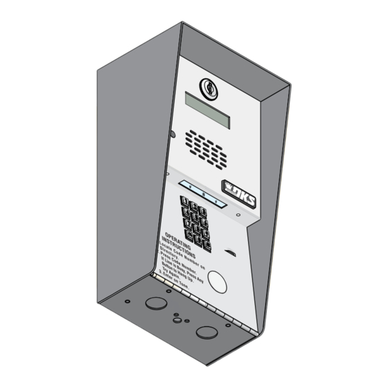
Installation/Owner's Manual
Use this manual for circuit board 1970-010 Revision U or higher.
1802
1802
1802
Access Plus
1808
1808
1808
Access Plus
1810
1810
1810
Access Plus
Date Installed:
Installer/Company Name:
Phone Number:
Leave Manual with Owner
UL Listed
PC Programmable Telephone Entry/Access Control System
S u
r f a
c e
1 8
0 2
- 0 9
2
Copyright 2016 DoorKing, Inc. All rights reserved.
1802 1808 1810 Access Plus
1802 1808 1810 Access Plus
1802 1808 1810 Access Plus
Control a main door, gate and six additional RS-485 entry points.
M o
u n
t
S u
r f a
1 1
2 2
3 3
4 4
5 5
7 7
6 6
8 8
9 9
0 0
1 8
0 8
- 0 8
5
S u
r f a
c e
M o
u n
t
1 1
2 2
4 4
3 3
5 5
7 7
6 6
8 8
9 9
0 0
1 8
1 0
- 0 9
5
Circuit Board
Serial Number
and Revision Letter:
c e
M o
u n
t
N A
N A
M E
M E
A d
A d
a m
a m
B e rn
B e rn
s J
s J
C O
C O
D E
D E
a rd
a rd
B ro
B ro
E
E
w n
w n
1
1
D a
D a
L
L
v is
v is
9
9
H o
H o
T
T
d g
d g
e s
e s
5
5
M il
M il
le r
le r
S
S
2
2
S m
S m
J
J
it h
it h
4
4
T h o
T h o
K
K
m a
m a
6
6
Z im
Z im
s W
s W
m e
m e
8
8
r R
r R
3
3
7
7
1 8
1 0
Copyright 2009 DoorKing, Inc. All rights reserved.
1810-162-A-6-16
F l u
s h
M o
u n
t
1 1
2 2
4 4
3 3
5 5
7 7
6 6
8 8
9 9
0 0
- 0 9
6
Advertisement
Chapters
Table of Contents
Troubleshooting

Summary of Contents for Intertek 1802
- Page 1 Installation/Owner’s Manual 1802 1808 1810 Access Plus 1802 1808 1810 Access Plus 1802 1808 1810 Access Plus PC Programmable Telephone Entry/Access Control System Use this manual for circuit board 1970-010 Revision U or higher. 1810-162-A-6-16 Control a main door, gate and six additional RS-485 entry points.
-
Page 2: Quick Guide
QUICK GUIDE: Terminals & LED Descriptions Phone In 18-PIN Terminal 1970-010 (Twisted Pair) 1. Phone In (Negative - Ring) Wireless 2. Phone In (Positive - Tip) Adapter 3. Ground (Required) 4. Phone Out (Positive - Tip) Phone Out (Twisted Pair) 5. -
Page 3: Quick Reference Table
Quick Reference Table Page # Section Command Factory Settings Section 2.1 Programming Master Code Program a Master Code Press Master NO Master Code Code Button Programmed Section 2.3 Programming Network Setup for a Computer Enable / Disable TCP / IP Support - System Reboot 2.3.1 * 5 0 Set the Unit’s IP Address (reboot required) -
Page 4: Specifications
SPECIFICATIONS For 1802/1808/1810 Access Plus with circuit board -4 8 - 4 5 J a c ( C a t5 ) Interface Board 1970-010 Rev U or higher ONLY. - 0 1 J 3 J M IC Control Board Both Boards Together - 1970-010... -
Page 5: Table Of Contents
Important Notices FCC - United States, DOC - Canada General Information Installation Guidelines and Safety Information SECTION 1 - INSTALLATION 1.1 Mount the Access Plus System 1.1.1 1802 Access Plus 1.1.2 1808 Access Plus 1.1.3 1810 Access Plus Surface Mount 9-11 1.1.4... - Page 6 TABLE OF CONTENTS 2.5 Directory Codes 2.5.0 Directory Codes 01 – 23 PRE-SET (1816 Access Plus Telephone Interface ONLY) 2.5.1 Directory Codes 24 – 50 Programming “Dial Phone Number” 2.5.2 Delete a Phone Number from Directory Codes 24 – 50 2.5.3 Delete ALL Phone Numbers from Directory Codes 24 –...
-
Page 7: Important Notices Fcc - United States, Doc - Canada
Important Notices FCC – United States This equipment has been tested and found to comply with the limits for a class A digital device, pursuant to Part 15 of the FCC Rules and Regulations. These limits are designed to provide reasonable protection against harmful interference when the equipment is operated in a commercial environment. -
Page 8: General Information Installation Guidelines And Safety Information
General Information • Prior to beginning the installation of the telephone entry system, we suggest that you become familiar with the instructions, illustrations, and wiring guidelines in this manual. This will help insure that you installation is performed in an efficient and professional manner. •... -
Page 9: Section 1 - Installation
SECTION 1 - INSTALLATION Installation of the Access Plus Telephone Entry System involves the installation of the hardware and the wiring of these compo- nents. Be sure that all dirt, metal or wood debris is removed from inside after mounting it. Any debris inside could damage the control board and cause the Access Plus system to malfunction during operation. -
Page 10: 1802 Access Plus
1.1.1 1802 Access Plus Surface mount units can be mounted directly to a wall, pilaster, post mounted using a DoorKing Adapter Plate (P/N 1802-111) with DoorKing mounting posts (P/N 1200-036, 1200-045, 1200-0046 and 1200-049). See next page. Be sure the unit is mounted securely and is not subject to vibration from closing doors or gates. - Page 11 1.1.1 1802 Access Plus Continued The illustrations below show typical installations but specific installations can vary from this. 1. Mount the enclosure using the mounting holes provided in the corners (see sections 1.2 and 1.3 for your chosen model dimensions). Be sure that mounting screws or nuts (Not supplied) do not protrude into the enclosure where they could cause a short on the back of the circuit board.
-
Page 12: 1808 Access Plus
1.1.2 1808 Access Plus 1808 units can be mounted directly to a wall, pilaster, post mounted using a DoorKing mounting post (P/N 1200-045 or 1200-046). Be sure the unit is mounted securely and is not subject to vibration from closing doors or gates. Creating Printed Directories for 1808 unit: WARNING! If this entry... -
Page 13: 1810 Access Plus Surface Mount
1.1.3 1810 Access Plus Surface Mount Surface mount units can be mounted directly to a wall, pilaster, post mounted using a DoorKing architectural style mounting post (P/N 1200-037 and 1200-038) or recessed in a wall with the surface mount recess kit (P/N 1803-150). Be sure the unit is mounted securely and is not subject to vibration from closing doors or gates. - Page 14 1.1.3 1810 Access Plus Surface Mount Continued The illustrations below show typical surface mount installations but specific installations can vary from this. 1. Mount the enclosure using the mounting holes provided in the corners. Be sure that mounting screws (Not supplied) do not protrude into the enclosure where they could cause a short on the back of the circuit board.
- Page 15 1.1.3 1810 Surface Mount Recess Kit Mount In a Surface c k n 1810 surface mount unit can be recessed into a wall or pilaster by using the optional surface mount recess kit if desired (P/N P l a s t i c 1803-150).
-
Page 16: 1810 Access Plus Flush Mount
1.1.4 1810 Access Plus Flush Mount Flush mount 1810 is installed with a flush mount kit P/N 1814-165 (stainless) or 1814-166 (gold). Flush mount kits are NOT INCLUDED with the flush mount entry system (See next page for flush mount kit installation). The flush mount units may also be installed ON the surface of a wall with a flush mount surface mounting kit if desired P/N 1814-152 (silver only). - Page 17 1.1.4 1810 Flush Mount Kit c k n The flush mount kit has two P l a s t i c parts; the rough-in box and the a c e Mount In a Surface trim ring. The rough-in box is installed in the wall first.
- Page 18 1.1.4 1810 Flush Mount Surface Mounting Kit Flush mount unit can be mounted ON a t i n ( N o t s u wall or pilaster and NOT IN the wall by c r e l i e d Mount On a Surface using the optional flush mount surface mounting kit (P/N 1814-152).
- Page 19 1.1.4 1810 Self-Standing Lighted Kiosk The flush mount kit (Sold separately, see previous page) is installed into P l a c k n s t i c the self-standing kiosk (P/N 1200-170) to secure the flush mount 1810 a c e in place.
-
Page 20: Postal Lock Installation
Post Office uses for gang mailboxes. These locks are not available to the public. The installer or the building owner/manager will have to call the Post Office and arrange for the installation of this lock into the access plus system. DoorKing 1802 & 1810 access plus systems are designed to accept installation of the postal lock. -
Page 21: Telephone Line Wire
1.3 Telephone Line Wire Be sure to observe electrical safety when working with phone lines. Phone lines carry electricity and the ring voltage can deliver a substantial jolt. In most residences, the phone cable contains four wires; green, red, black, yellow. The green and red are twisted to make one pair and the black and yellow are twisted to make another pair (This allowed for the addition of a second phone line since telephones use only two wires). -
Page 22: Vac Power Wiring Only
1.4 16.5 VAC Power Wiring ONLY! The Access Plus system operates ONLY on 16.5 VAC. DO NOT power the unit with 24 volt AC power. Use the supplied power transformer, 16 VAC, 20 VA (or U.L. listed equivalent) to power the telephone entry system. DO NOT power any other devices (electric strikes, magnetic locks, etc.) from the unit’s power transformer. -
Page 23: Wire One Unit To A Telco Line - Auto-Dialer
1.6 Wire ONE Unit to a Telco Line - Auto-Dialer Connect to Incoming Telephone Company’s 1877-010 Optional Phone Line Surge Suppressor Phone Line DoorKing Surge Suppressor P/N 1877-010 (or equivalent) is optional but Locate the telephone company demarcation device. highly recommended. IMPORTANT Identify the telephone line that will connect to the Access Plus For best protection, surge suppressor ground... -
Page 24: Wire One Unit To The Internet - Auto-Dialer
1.7 Wire ONE Unit to the Internet - Auto-Dialer Typical “Existing” Internet Source Internet Internet DSL/Cable Modem Router RJ-11 Phone Telephone Line (Cat5e) Connector For complete information, see section 1.3. Cat5e TIP (+): White/blue mark RING (-): Blue/white mark Phone Check Polarity of Telephone Line Jack Check for polarity on the phone “IN”... -
Page 25: Wire Multiple Units - Auto-Dialer: Telco/Internet
1.8 Wire Multiple Units - Auto-Dialer: Telco/Internet 1877-010 Optional Phone Line Surge Suppressor DoorKing Surge Suppressor P/N 1877-010 (or equivalent) is optional but highly recommended for Telco line. For best protection, surge suppressor ground wire MUST be PHONE LINE 3-ft. or less in length. Use minimum 12 AWG wire. Refer to INPUT OUTPUT instruction sheet included with surge board and section... -
Page 26: 1816 Access Plus Telephone Interface Wiring
1.9 1816 Access Plus Telephone Interface Wiring Telco Phone Line - OPTIONAL The RJ71 wiring configuration is not recognized by 1816 Access Plus Telephone Interface is used Relay 00 is reserved for Central Office (C.O.) all telephone companies. For Bell Canada (Ontario, in a complex to connect to the tenant/resident phone line ONLY when using Access Plus Quebec), refer to CA-79X block for interconnection... - Page 27 1.9 Continued 1816 Access Plus Telephone Interface Telephone Wire Run Table Decoder Wire Size Max Distance 2 3 4 5 6 7 8 Board DIP-switches 24 AWG 800 ft MUST be ON. 22 AWG 1600 ft 20 AWG 2200 ft 18 AWG 3600 ft DOORKING 1881-010 DECODER BOARD...
-
Page 28: Main Terminal Description
1.10 Main Terminal Description Phone In 1970-010 (Twisted Pair) 1. Phone In (Negative - Ring) Wireless 2. Phone In (Positive - Tip) Adapter 3. Ground (Required) 4. Phone Out (Positive - Tip) Phone Out (Twisted Pair) 5. Phone Out (Negative - Ring) 6. - Page 29 RS-485 Daisy Chain Wiring 1970-010 1970-010 Terminals 1 and 2 MUST be twisted. RS-485 DATA A (+) RS-485 DATA B (-) RS-485 RX MASTER MASTER RS-485 Common TERMINATION TERMINATION CODE CODE TERMINATION LAN DOWN BAD DNS MODEM / TCP ENB When 3 RS-485 wires are connected to terminal, DATA TRANSMIT...
-
Page 30: Rs-485 Daisy Chain Wiring
RS-485 Configurations CORRECT Configuration Samples Terminated Internal Addresses Device Device Address 001 for Relay 1 Term Sw Maximum of six (6) 002 for Relay 2 Address (Factory Set) devices allowed. Every RS-485 device (keypad, card reader, MicroPlus RF receiver) must have a unique address assigned to it, starting 1 Device CODE Any RS-485 Keypad,... -
Page 31: Rs-485 Configurations, Sample Of Multiple Unit Configuration Connection (Auto-Dialer Only)
Auto-Dialer ONLY - Sample of Multiple Units Configuration Connection Phone Company Maximum of 5 Units Maximum of 6 RS-485 Devices “Daisy Chain” per Unit Relay 3 Relay 4 Relay 5 Relay 6 Relay 7 Relay 8 Term Sw Term Sw Term Sw Term Sw Term Sw... -
Page 32: Network Connections
1.11.2 Network Connections There are a number of ways to communicate with the Access Plus system via a network connection. Before any programming can be attempted, you need to install the Access Plus programming software on the computer you want to use for this purpose. The computer must have a network card installed. - Page 33 Through the Internet (WAN) • Through the internet with a static IP address. This is a Wide Area Network (WAN) connection and will require a router and a DSL or cable modem with an internet connection. • Through the internet with a dynamic IP address. This is a Wide Area Network (WAN) connection and will require a router and a DSL or cable modem with an internet connection.
-
Page 34: Phone Modem Connection
1.11.3 Phone Modem Connection The Access Plus system has a dedicated phone line. A PC MUST be connected to a separate phone line to program the Access Plus system. Phone Modem Connection: DIFFERENT Access Plus system and PC connected on phone lines. -
Page 35: Section 2 - Programming
SECTION 2 - PROGRAMMING Before You Start Programming: IMPORTANT! Make sure the Access Plus system has power and we strongly suggest that you become familiar with these programming instructions before beginning any programming of the Access Plus system. The unit has been programmed at the factory with many of the programming parameters already set (default setting) for a typical residential application with a single unit. -
Page 36: Programming Methods
2.2 Programming Methods The Access Plus system can be programmed from a computer, the system keypad (Keypad on the unit) or from a touch-tone telephone. NAME CODE Adams J Bernard E Brown L Davis T Hodges S Miller J Smith K Thomas W Zimmer R Direct “System Keypad”... -
Page 37: Programming The Network Setup For A Computer
2.3 Programming the Network Setup for a Computer Before proceeding with any of the programming steps in this section, install the Access Plus Management software on the computer (PC ONLY) that will be used for this purpose. Be sure that the computer has a network card installed, or a modem installed in it (or connected to it) depending on which connection method will be used. -
Page 38: Sub-Net Mask (Reboot Required)
2.3.3 Sub-Net Mask (reboot required) Factory setting is: 255.255.255.000 All sub-net mask should be set to 255.255.255.000. This rarely needs to be changed, consult with your network expert first. Valid values for any of the three digit numbers is 000 to 255. 1. -
Page 39: System Parameters Programming
2.4 System Parameters Programming IMPORTANT! We strongly suggest that you read these programming instructions in their entirety before beginning any manual programming of the Access Plus system. The programming table on the next page provides a quick reference to: Programming from the System Keypad Follow the programming instructions as described in each section of this manual. -
Page 40: Quick Reference Table
Quick Reference Table Page # Section Command Factory Settings Section 2.1 Programming Master Code Program a Master Code Press Master NO Master Code Code Button Programmed Section 2.3 Programming Network Setup for a Computer Enable / Disable TCP / IP Support - System Reboot 2.3.1 * 5 0 Set the Unit’s IP Address (reboot required) -
Page 41: Single Or Multiple Systems
2.4.2 Single or Multiple Systems Factory setting is 1 (Single System). Set for single if the unit is the only unit connected to the phone line, or set to multiple if more than one unit is connected to the phone line. 1. -
Page 42: Talk Time
2.4.6 Talk Time Factory setting is 060 (60 Seconds). This programming sequence sets the maximum time allowed for conversation when the Access Plus unit places a call either through the 1816 Access Plus telephone interface (directory codes 01-23) or through the auto-dialer (directory codes 24-50). -
Page 43: Answer Incoming Call On X Rings
2.4.9 Answer Incoming Call on X Rings Factory setting is 06 (6 Rings). This programming section sets the number of rings that the unit will allow to pass through the system before it picks up the call. The number of rings to answer can be set from 1 to 99 rings and must be entered as a two-digit number. For example, if you want the unit to answer the call after the sixth ring, enter 0 6 in step 2. -
Page 44: Set Call Forward Microphone Gain And Speaker Volume
2.4.13 Set Call Forward Microphone Gain and Speaker Volume Factory setting is 71 (7 - Microphone, 1 - Speaker). This adjustment is required only if the Access Plus unit is being used in the auto-dialer mode (directory codes 24-50). This step will adjust the microphone gain (the remote handset loudness) and the speaker volume (the Access Plus unit loudness) during call forwarding operation. -
Page 45: Delete A Phone Number From Directory Codes
2.5.2 Delete a Phone Number from Directory Codes 24 – 50 This programming sequence deletes individual directory code dial-out phone numbers from the system memory. WARNING: once deleted, this CANNOT be undone. 1. Press 4 2 and enter the MASTER CODE. [ 4 2 _ _ _ _ (beep)] 2. -
Page 46: Additional Off-Line Relay Function
2.6.3 Additional Relay Off-Line Function Factory setting is 0 (No Devices Connected). This programming sequence sets how the remote RS-485 devices connected to the Access Plus unit will respond if the RS-485 communication link fails to a specific remote device. Entering a 1 in step 2 sets the remote device to GRANT ACCESS to any five-digit card, transmitter or access code, whether it has been programmed into the system or not at the specific device location where the RS-485 communication link failed. -
Page 47: Temporary Device Access Code Programming
2.6.7 Temporary Device Access Code Programming This programming sequence programs up to 10 temporary device access codes with a beginning and ending date and any time zone restrictions that may need to be applied. 1. Press 7 3 and enter the MASTER CODE. [ 7 3 _ _ _ _ (beep)] 2. -
Page 48: Time Functions
2.7 Time Functions 2.7.1 Time and Date Calendar Chip Programming This programming sequence programs the calendar chip in the Access Plus system for the current time and date. The calendar chip must be programmed if any of the time related features are going to be used. Note: The clock / calendar chip in the Access Plus system will keep time for approximately 48 hours if power to the system is lost or removed. -
Page 49: Access Code Time Zone Programming (Up To 4)
2.7.6 Access Code Time Zone Programming (Up to 4 zones) Factory setting in step 3 is 0 (Time Zones are OFF). This programming sequence sets up time zones (up to 4) that can be applied to the “Access Codes” programmed in section 2.6.4 into the Access Plus system. -
Page 50: Section 3 - Adjustments
SECTION 3 - ADJUSTMENTS Speaker Volume The speaker volume potentiometer is labeled SPEAKER VOL on the control board. The speaker volume should be adjusted for adequate sound. Adjusting the speaker volume too loud could cause feedback from the microphone. 1. Open the front of the telephone entry system and locate the speaker volume adjustment. 2. -
Page 51: Section 4 - User Instructions
SECTION 4 - USER INSTRUCTIONS 4.1 Resident Operating Instructions 4.1.1 Granting or Denying a Guest Access To place a call from the Access Plus unit to a residence, the guest locates the directory code of the resident they want to visit, and then enters that code on the unit’s keypad. -
Page 52: Remote Operation
4.2 Remote Operation 4.2.1 Remote Programming (Touch-Tone Phone) The Access Plus unit can be programmed and operated from a touch-tone telephone. Be sure that the ability for the unit to answer an incoming call has not been disabled (section 2.4.9). Note: The master code cannot be programmed remotely, it can only be programmed from the system keypad (section 2.1). -
Page 53: Section 5 - Maintenance
SECTION 5 - MAINTENANCE The DoorKing Access Plus system is essentially a maintenance free device. When the unit is properly installed, it should provide years of trouble free service. Maintenance is limited to updating the access codes on an as needed basis. The faceplate of the unit should be cleaned on a regular basis to keep contaminants in the air from sticking to the surface and possibly causing pitting. -
Page 54: Phone Line Polarity
5.2 Phone Line Polarity When troubleshooting Access Plus system operational problems, check phone line polarity. Crossed polarities can affect system operation. Phone Line Surge Suppressor 1877-010 Optional Phone Line Surge Suppressor DoorKing Surge Suppressor Central Office Telephone P/N 1877-010 (or equivalent) is optional but highly Phone Line Inside Device Company recommended for Telco line. -
Page 55: Troubleshooting Table
5.3 Troubleshooting Table Symptom Possible Solution(s) Board does not power up. • No power. Check for 16 VAC input power. • If OV LED is ON, input voltage is too high. Insure that the transformer connected to the input terminals is 16 VAC. -
Page 56: Access Plus Wiring Schematic
Speaker Orange Gray LED Light Board LED Note: 1802 - 1 LED Light Board LED Light Board LED Light Board 1808 - 2 LED Light Boards 1810 Surface mount - 3 LED Light Boards 1810 Flush mount - 2 LED Light Boards... -
Page 57: Accessories
5.5 Accessories RS-485 Card Readers P/N 1815-232 (uses DKS reader) P/N 1815-233 (uses AWID reader) P/N 1815-234 (uses HID reader) RS-485 Keypads P/N 1513-080 (surface mount, non-lighted) P/N 1513-081 (surface mount, lighted) P/N 1513-082, (flush mount, lighted) RS-485 RF Receiver P/N 8053-080 (MicroPlus receiver) Secondary Keypads: Allows remote activation of the system relays by use of the access codes. -
Page 58: Programmed Information Log Sheets
5.6 Programmed Information Log Sheets Complete the information in the tables on the following pages to maintain a record of the information that has been programmed into the Access Plus system. Access Plus system manual is available on-line at: www.dkaccess.com if extra log sheets are required. - Page 59 Directory Codes 1 – 23 / Pre-Set Numbers (1816 Telephone Interface ONLY) Directory Code Name Apartment Number 1810-162-A-6-16...
- Page 60 Directory Codes 24 – 50 / Dial-Out Phone Numbers Directory Code Name Phone Number 1810-162-A-6-16...
- Page 61 1-25 Access Codes Log Sheet (With Phone Numbers) Time Zone Restricted Information Access Code # and Device Type: Simple or Time Zone Relay: Momentary Type Time Zone Restricted Name / Phone Number (Optional) Number or Hold (Latch) 1810-162-A-6-16...
- Page 62 26-50 Access Codes Log Sheet (With Phone Numbers) Time Zone Restricted Information Access Code # and Device Type: Simple or Time Zone Relay: Momentary Type Time Zone Restricted Name / Phone Number (Optional) Number or Hold (Latch) 1810-162-A-6-16...
- Page 63 1-25 Access Codes Log Sheet (Access Only) Time Zone Restricted Information Access Code # and Device Type: Simple or Time Zone Relay: Momentary Type Time Zone Restricted Name Number or Hold (Latch) 1810-162-A-6-16...
- Page 64 26-50 Access Codes Log Sheet (Access Only) Time Zone Restricted Information Access Code # and Device Type: Simple or Time Zone Relay: Momentary Type Time Zone Restricted Name Number or Hold (Latch) 1810-162-A-6-16...
- Page 65 1-10 Temporary Access Codes Log Sheet (When using software ONLY) Relay: Temporary Device Beginning Ending Time Zone Momentary Name Access Code # Type Date Date Number or Hold (Latch) (section 2.6.7) 1-10 Temporary Access Codes Log Sheet extra log sheet Relay: Temporary Device...
-
Page 66: 1810-162
Installation/Owner’s Manual 1802 1808 1810 Access Plus 1802 1808 1810 Access Plus 1802 1808 1810 Access Plus PC Programmable Telephone Entry/Access Control System Use this manual for circuit board 1970-010 Revision U or higher. 1810-162-A-6-16 Control a main door, gate and six additional RS-485 entry points.
Need help?
Do you have a question about the 1802 and is the answer not in the manual?
Questions and answers