Table of Contents
Advertisement
Quick Links
Advertisement
Table of Contents
Troubleshooting

Related Manuals for Allied Telesis AT-220-28GS Series


Summary of Contents for Allied Telesis AT-220-28GS Series
- Page 1 Questo manuale d’istruzione è fornito da trovaprezzi.it. Scopri tutte le offerte per Allied Telesis x220-28GS o cerca il tuo prodotto tra le migliori offerte di Switch AT-x220-28GS Gigabit Ethernet Switch Installation Guide 613-02546-00 REV A...
- Page 2 Telesis, Inc. be liable for any incidental, special, indirect, or consequential damages whatsoever, including but not limited to lost profits, arising out of or related to this manual or the information contained herein, even if Allied Telesis, Inc. has been advised of, known, or should have known, the possibility of such damages.
- Page 3 Electrical Safety and Emissions Standards This product meets the following standards. U.S. Federal Communications Commission Radiated Energy Note: This equipment has been tested and found to comply with the limits for a Class A digital device pursuant to Part 15 of FCC Rules.
- Page 4 Translated Safety Statements Important: The indicates that a translation of the safety statement is available in a PDF document titled Translated Safety Statements posted on the Allied Telesis website at www.alliedtelesis.com.
-
Page 5: Table Of Contents
AT-x230-28GS Switch Installation Guide Contents Preface................................1 Symbol conventions ............................. 2 Contacting Allied Telesis..........................3 User documentation ............................. 4 Chapter Overview Features ............................... 6 SFP slots ............................... 6 Transceivers ............................6 USB slot..............................6 Console port ............................6 LEDs..............................6 Power conservation .......................... - Page 6 Contents Dimensions ............................47 Weight ..............................47 Environmental specifications ........................48 Power specifications........................... 48 Electrical safety and electromagnetic certifications ..................49 Connectors and port pinouts for the console port..................50...
- Page 7 Figures Figure 1: AT-x220-28GS packaging ............................8 Figure 2: AT-x220-28GS front panel............................9 Figure 3: AT-x220-28GS back panel ............................. 9 Figure 4: Power LED on the AT-x220-28GS Switch......................10 Figure 5: Fault LED on the AT-x220-28GS Switch ......................11 Figure 6: SFP Link/Speed/Activity LEDs on the AT-x220-28GS Switch................12 Figure 7: USB slot LED on the AT-x220-28GS Switch ......................
- Page 9 Tables Table 1. Power LED functional descriptions ........................10 Table 2. Fault LED functional descriptions .........................11 Table 3. SFP Link/Activity LED functional descriptions ......................12 Table 4. USB LED functional descriptions ..........................13 Table 5. Chassis dimensions ..............................47 Table 6. Chassis weight ..............................47 Table 7.
- Page 10 viii...
-
Page 11: Preface
AT-x220-28GS Switch Installation Guide Preface This guide contains the installation instructions for the AT-x220-28GS Gigabit Ethernet Switch. This preface contains the following sections: “Symbol conventions” on page 2 “Contacting Allied Telesis” on page 3 “User documentation” on page 4 ... -
Page 12: Symbol Conventions
Symbol conventions This document uses the following conventions: Note Notes provide additional information. Caution Cautions inform you that performing or omitting a specific action may result in equipment damage or loss of data. Warning Warnings inform you that performing or omitting a specific action may result in bodily injury. -
Page 13: Contacting Allied Telesis
AT-x220-28GS Switch Installation Guide Contacting Allied Telesis If you need assistance with this product, you may contact Allied Telesis technical support by going to the Support & Services section of the Allied Telesis web site at www.alliedtelesis.com/support. You can find links for... -
Page 14: User Documentation
User documentation For full AlliedWare Plus documentation and product information, see our Resource Library at: http://www.alliedtelesis.com/support From the Resource Library the following documents are available: Datasheets Click on the link above and search for the product series. Installation guides ... - Page 15 AT-x220-28GS Switch Installation Guide Chapter 1 Overview This chapter provides descriptions of the AT-x220-28GS Gigabit Ethernet Switch and contains the following sections: “Features” on page 6 “Package contents for the AT-x220-28GS Switch” on page 8 “Front and back panels on the AT-x220-28GS Switch” on page 9 ...
-
Page 16: Chapter 1: Overview
Support 100BASE-FX and 1000BASE-SX/LX SFP transceivers. SFP transceivers must be purchased separately. For a list of supported transceivers, contact your Allied Telesis distributor or reseller. Note See the product Datasheet for the specific ATI SFP modules supported by the x220-28GS switch. -
Page 17: Power Conservation
AT-x220-28GS Switch Installation Guide Note The ecofriendly button on the Management Panel turns off the port LEDs to conserve electricity (excluding the Fault, Power and USB LEDs). See “Ecofriendly button” on page 14. Power These switches have the following power conservation features: conservation Ecofriendly button to turn off the port LEDs when the system is not ... -
Page 18: Package Contents For The At-X220-28Gs Switch
Chapter 1: Overview Package contents for the AT-x220-28GS Switch Figure 1 illustrates the package components that come with the AT-x220- 28GS Gigabit Ethernet Switch. Figure 1. AT-x220-28GS packaging One 2 m (6.6ft) local management cable with RJ-45 (8P8C) and DB-9 (D-sub 9-pin) One regional AC power cord Power cord retaining clip Two rack/wall mounting brackets... -
Page 19: Front And Back Panels On The At-X220-28Gs Switch
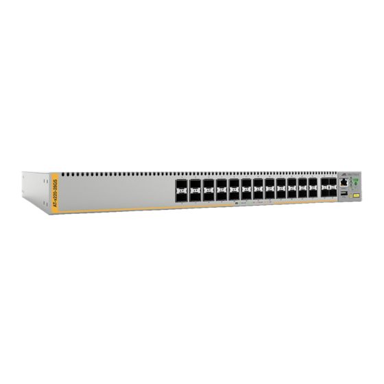
AT-x220-28GS Switch Installation Guide Front and back panels on the AT-x220-28GS Switch Figure 2 illustrates the front panel of the AT-x220-28GS Gigabit Ethernet Switch. Figure 2. AT-x220-28GS front panel SFP Network ports SFP uplink ports SFP port LEDs: Upper (left), lower (right) USB/Fault/Power LEDs FAULT ecofriendly button... -
Page 20: Leds
Chapter 1: Overview LEDs This section describes the four types of LEDs on the AT-x220-28GS switch: “Power and Fault LEDs” on page 10 “SFP LEDs” on page 11 “USB LED” on page 13 Power and Fault The Power LED reports the status of AC power and is located on the Management Panel of the switches beside the console port. -
Page 21: Sfp Leds
AT-x220-28GS Switch Installation Guide Figure 5 shows the location of the Fault LED. Figure 5. Fault LED on the AT-x220-28GS Switch Fault LED FAULT POWER CONSOLE CLASS 1 LASER PRODUCT Table 2 describes the functions of the Fault LED. Table 2. Fault LED functional descriptions State Description If the POWER LED is on, the switch is receiving... -
Page 22: Figure 6: Sfp Link/Speed/Activity Leds On The At-X220-28Gs Switch
Chapter 1: Overview Figure 6. SFP Link/Speed/Activity LEDs on the AT-x220-28GS Switch Upper (left) SFP LED Lower (right) SFP LED SFP slots CONSO Table 3 describes the functions of the SFP Link/Speed/Activity LEDs: Table 3. SFP Link/Activity LED functional descriptions State Description The port on the SFP transceiver has not... -
Page 23: Usb Led
AT-x220-28GS Switch Installation Guide USB LED The AT-x220-28GS switch has a single bi-color USB LED on the Management Panel (see Figure 7) Note All of the port LEDs are off when the switch is operating in ecofriendly mode. See “Ecofriendly button” on page 14 for more information. -
Page 24: Ecofriendly Button
Chapter 1: Overview Ecofriendly button By pressing the ecofriendly button on the Management Panel, you can conserve energy. Using the button When you press the ecofriendly button for 1 to 4 seconds, the front panel port LEDs are disabled. You may use the button to turn off the LEDs when you are not monitoring the switch. -
Page 25: Power Supply
AT-x220-28GS Switch Installation Guide Power supply Each switch has an internal power supply with a single AC power supply socket on the back panel. A power cord and a power cord retainer hook are supplied with the switch. The power supply is not field replaceable. Warning Power cord is used as a disconnection device. - Page 26 Chapter 1: Overview...
- Page 27 AT-x220-28GS Switch Installation Guide Chapter 2 Installation This chapter contains the following sections: “Reviewing safety precautions” on page 18 “Selecting a site for the switch” on page 21 “Unpacking the switch” on page 22 “Installing the switch on a table or a desktop” on page 23 ...
-
Page 28: Chapter 2: Installation
Chapter 2: Installation Reviewing safety precautions Please review the following safety precautions before you begin to install the chassis or any of its components. Note The indicates that a translation of the safety statement is available in a PDF document titled Translated Safety Statements. - Page 29 Use dedicated power circuits or power conditioners to supply reliable electrical power to the device. E27 Warning The chassis may be heavy and awkward to lift. Allied Telesis recommends that you get assistance when mounting the chassis in an equipment rack. E28...
- Page 30 Chapter 2: Installation Warning Reliable earthing of rack-mounted equipment should be maintained. Particular attention should be given to supply connections other than direct connections to the branch circuits (e.g., use of power strips). E37 Caution The unit does not contain serviceable components. Please return damaged units for servicing.
-
Page 31: Selecting A Site For The Switch
AT-x220-28GS Switch Installation Guide Selecting a site for the switch You can install an AT-x220-28GS switch on a table or desktop, in a standard 19-inch equipment rack, or on a wall. Observe the following requirements when choosing a site for your switch: If you are installing the switch on a table, verify that the table is ... -
Page 32: Unpacking The Switch
Chapter 2: Installation Unpacking the switch To unpack the switch, perform the following procedure: 1. Remove all of the components from the shipped package. Note Store the packaging material in a safe location. You must use the original shipping material if you need to return the unit to Allied Telesis. -
Page 33: Installing The Switch On A Table Or A Desktop
AT-x220-28GS Switch Installation Guide Installing the switch on a table or a desktop Here are the guidelines to selecting a suitable site for desktop or table use: Review the procedure “Selecting a site for the switch” on page 21 to verify that the selected site is suitable for your switch. -
Page 34: Figure 10: Inserting The Assembled Rivets Into The Hole In The Foot
Chapter 2: Installation 4. Insert the rivet through the hole in the feet as shown in Figure 10 on page 24. Figure 10. Inserting the assembled rivets into the hole in the foot Insert all assembled rivets into the holes in the feet 5. -
Page 35: Removing The Feet Before Installing The Switch In An Equipment Rack Or On A Wall
AT-x220-28GS Switch Installation Guide Removing the feet before installing the switch in an equipment rack or on a wall Before you install the switch in a 19-inch equipment rack or on a wall, you need to remove the rubber feet, if they are attached to the base of the switch. -
Page 36: Installing The Switch In An Equipment Rack
Chapter 2: Installation Installing the switch in an equipment rack These instructions show you how to install the switch in an equipment rack. The rack mount kit is included in the packaging and includes two rack mount brackets and eight bracket screws. To install one of these switches in a 19-inch equipment rack, follow these steps: 1. -
Page 37: Figure 15: Mounting The At-X220-28Gs Switch In An Equipment Rack
AT-x220-28GS Switch Installation Guide 4. Mount the switch in a 19-inch equipment rack using four equipment rack screws (not supplied). Figure 15. Mounting the AT-x220-28GS switch in an equipment rack 1 0 0 IN K 1 0 0 L IN LA SE CL AS R PR... -
Page 38: Installing The Switch On A Wall
Chapter 2: Installation Installing the switch on a wall These instructions show you how to install the switch on a wall. The rack/ wall mount brackets and screws are provided along with the screws for securing the switch to a wall with wooden studs. Concrete anchors are also provided for concrete walls. -
Page 39: Positions Of The Switch On A Wall
AT-x220-28GS Switch Installation Guide Positions of the The switch may be installed on the wall with the front panel on the left or right with the brackets placed diagonally as shown in Figure 16. switch on a wall Do not install the switch with the front panel on the top or the bottom. Figure 16. - Page 40 Chapter 2: Installation Left facing Figure 17. Attaching wall mount brackets so that the switch is left facing Right facing Figure 18. Attaching wall mount brackets so that the switch right facing 3. While another person holds the switch at the wall location, use a pencil to mark the wall with the locations of the two screw holes for each bracket.
-
Page 41: Figure 19: Marking The Screw Holes From The Brackets To The Wall
AT-x220-28GS Switch Installation Guide Figure 19. Marking the screw holes from the brackets to the wall 4. While another person holds the switch at the marked wall location, use a drill to make the holes for the two screws for each bracket. (Figure 20). -
Page 42: Powering On The Switch
Chapter 2: Installation Powering on the switch To power on the switch, perform the following procedure: 1. Attach the power cable hook and lift to the up position ready for the AC power plug to be inserted, as shown in Figure 21, on the back of the switch. - Page 43 AT-x220-28GS Switch Installation Guide 3. Plug the other end of the power cord into a wall outlet. Warning Power cord is used as a disconnection device. To de-energize equipment, disconnect the power cord. E3 Pluggable Equipment: The socket outlet shall be installed near the equipment and shall be easily accessible.
-
Page 44: Management Software
Chapter 2: Installation Management software The switches are shipped with the management software pre-installed. The software provides a command line interface and a GUI (Graphical User Interface) for in-band, over-the-network management. In the unlikely event that the management software becomes corrupted or damaged on the switch, you can download the software from the Allied Telesis corporate web site and reinstall it on the switch. -
Page 45: Starting A Local Management Session
AT-x220-28GS Switch Installation Guide Starting a local management session This procedure requires a terminal or a terminal emulator program and the management cable that comes with the switch. To start a local management session on the switch, perform the following procedure: 1. -
Page 46: Monitoring The Initialization Processes
/ /______\ \ \_ __/ /| ______ | | ______ | \ ____ / /______/\____\ \/ /____________/ Allied Telesis Inc. AlliedWare Plus (TM) v0.0.0 Current release filename:x220-5.4.8.rel Built: Fri Mar 23 07:06:12 UTC 2018 Mounting static filesystems... Attaching to /dev/mtd0... -
Page 47: Figure 25: Switch Initialization Messages (Continued)
AT-x220-28GS Switch Installation Guide Figure 25. Switch initialization messages (continued) Received event modules.done Starting base/reboot-stability... Checking system reboot stability... Starting base/apteryx... Starting base/crond... Starting base/appmond... Starting base/clockcheck... Starting base/inet... Received event apteryx.done Starting hardware/early_host_info... Starting base/eventwatch... Starting base/alfred... Starting network/kermond... Starting base/apteryx-sync... -
Page 48: Figure 26: Switch Initialization Messages (Continued)
Chapter 2: Installation Figure 26. Switch initialization messages (continued) Assigning Active Workload to HA processes: hsl, irdpd, lacpd, loopprotd, mstpd, nsm, ripd rmond, sflowd, authd, epsrd, lldpd, imi, imiproxyd Received event network.activated Loading default configuration Warning: flash:/default.cfg does not exist, loading factory defaults. done! Received event network.configured awplus login:... -
Page 49: Cabling The Network Ports
For a list of supported transceivers, refer to the product data sheet on the Allied Telesis web site. The operational specifications and fiber optic cable requirements of the transceivers are provided in the documents included with the devices. -
Page 50: Installing Sfp Transceivers
2. Position the SFP transceiver with the Allied Telesis label facing up for the top SFP slots. Position the SFP transceiver with the Allied Telesis label facing down for the bottom SFP slots. -
Page 51: Figure 28: Positioning The Sfp Handle In The Upright Position
AT-x220-28GS Switch Installation Guide 4. Verify that the handle on the transceiver is in the upright position, as shown in Figure 28. This secures the transceiver and prevents it from being dislodged from the slot. If the transceiver is in a bottom slot verify the handle is in the downright position. - Page 52 Chapter 2: Installation...
-
Page 53: Chapter 3: Troubleshooting
Troubleshooting This chapter contains information on how to troubleshoot the switch if a problem occurs. Note For further assistance, please contact Allied Telesis Technical Support at www.alliedtelesis.com/support. Problem 1: The power LED on the front of the switch is off. - Page 54 Chapter 3: Troubleshooting Verify that the correct type of fiber optic cabling is being used. Verify that the port is connected to the correct fiber optic cable. This is to eliminate the possibility that the port is connected to the wrong remote network device, such as a powered off device.
-
Page 55: Appendix A: Technical Specifications
AT-x220-28GS Switch Installation Guide Appendix A Technical specifications This appendix describes the technical specifications of an x220 series switch. Physical specifications Dimensions 5. C ABLE HASSIS DIMENSIONS Model W x D x H mm (in) 341 mm x 231mm x 44mm AT-x220-28GS (13.42 in x 9.10 in x 1.73 in) Weight... -
Page 56: Environmental Specifications
Appendix A: Technical specifications Environmental specifications 7. E ABLE NVIRONMENTAL SPECIFICATIONS Operating temperature 0° C to +50° C (32° F to 122° F) Storage temperature -25° C to 70° C (-4° F to 158° F) Operating humidity < 90% non-condensing Storage humidity <... -
Page 57: Electrical Safety And Electromagnetic Certifications
AT-x220-28GS Switch Installation Guide Electrical safety and electromagnetic certifications 10. S ABLE AFETY AND ELECTROMAGNETIC EMISSIONS CERTIFICATIONS EN 55024 EN 55032 Class A EN 61000-3-2 EN 61000-3-3 FCC Part 15 (CFR 47) Class A VCCI Class A CISPR 22 Class A ICES-003 Environmental RoHS... -
Page 58: Connectors And Port Pinouts For The Console Port
Appendix A: Technical specifications Connectors and port pinouts for the console port This section lists the connectors and connector pinouts for the management console port. Figure 30 illustrates the pin layout for an RJ45 connector for the console port. Figure 30. RJ45 connector and port pin layout Table 11 lists the RJ-45 style serial consol port pin signals.
Need help?
Do you have a question about the AT-220-28GS Series and is the answer not in the manual?
Questions and answers