Table of Contents
Advertisement
Quick Links
CONSOLE
MODE
FAULT
SPEED
RESET
STANDBY
SELECT
POWER
DUPLEX
RS-232
FAULT
RESET
POWER
Installation Guide
613-001769 Rev A
1
LINK /
ACT
L/A
MODE
SPEED / DUPLEX
L/A
1
3
5
7
9
11
13
15R
17
19
21
23R
MODE
L/A
2
4
6
8
10
12
14
16R
18
20
22
24R
MODE
2
L/A
LINK /
ACT
MODE
SPEED / DUPLEX
CONSOLE
1
3
5
7
9
11
13
15R
MODE
MODE
SPEED
SELECT
STANDBY
2
4
6
8
10
12
14
16R
MODE
DUPLEX
RS-232
CONSOLE
MODE
FAULT
SPEED
RESET
STANDBY
SELECT
POWER
DUPLEX
RS-232
AT-x210-24GT
AT-x210-16GT
AT-x210-9GT
Gigabit Ethernet Switches
3
5
7
9
11
13
4
6
8
10
12
14
1
3
5
7
9
11
L/A
L/A
2
4
6
8
10
12
1
3
5
L/A
LINK /
ACT
MODE
SPEED / DUPLEX
L/A
1
3
5
7
MODE
L/A
2
4
6
8
MODE
2
4
6
15R
17
19
21
23R
15
L/A
16
23
24
16R
18
20
22
24R
13
15R
AT-x210-16GT
Gigabit Ethernet Switch
SFP
15
16
15
16
14
16R
L/A
LINK /
ACT
7
AT-x210-9GT
Gigabit Ethernet Switch
SFP
CLASS 1
LASER PRODUCT
LINK /
ACT
L/A
8
9
AT-x210-24GT
Gigabit Ethernet Switch
LINK /
ACT
15
16
23
24
CLASS 1
LASER PRODUCT
SFP
CLASS 1
LASER PRODUCT
Advertisement
Table of Contents

Related Manuals for Allied Telesis AT-x210 Series


Summary of Contents for Allied Telesis AT-x210 Series
- Page 1 AT-x210-24GT AT-x210-16GT AT-x210-9GT Gigabit Ethernet Switches AT-x210-24GT LINK / Gigabit Ethernet Switch MODE SPEED / DUPLEX CONSOLE LINK / MODE MODE FAULT SPEED RESET STANDBY SELECT MODE CLASS 1 LASER PRODUCT POWER DUPLEX RS-232 AT-x210-16GT LINK / Gigabit Ethernet Switch MODE SPEED / DUPLEX CONSOLE...
- Page 2 Telesis, Inc. be liable for any incidental, special, indirect, or consequential damages whatsoever, including but not limited to lost profits, arising out of or related to this manual or the information contained herein, even if Allied Telesis, Inc. has been advised of, known, or should have known, the possibility of such damages.
- Page 3 Electrical Safety and Emissions Standards This product meets the following standards. U.S. Federal Communications Commission Radiated Energy Note: This equipment has been tested and found to comply with the limits for a Class A digital device pursuant to Part 15 of FCC Rules.
- Page 4 Translated Safety Statements Important: The indicates that a translation of the safety statement is available in a PDF document titled Translated Safety Statements posted on the Allied Telesis website at www.alliedtelesis.com.
-
Page 5: Table Of Contents
AT-x210-9GT, AT-x210-16GT, and AT-x210-24GT Switches Installation Guide Contents Preface................................1 Symbol Conventions ............................ 2 Contacting Allied Telesis..........................3 Chapter 1: Overview Features ................................6 Twisted Pair Ports ..........................6 SFP Slots............................... 6 LEDs..............................7 Installation Options ..........................7 Power Conservation ..........................7 MAC Address Table .......................... - Page 6 Contents...
- Page 7 Figures Figure 1: AT-x210-9GT, AT-x210-16GT, and AT-x210-24GT packaging................8 Figure 2: AT-x210-9GT, AT-x210-16GT, and AT-x210-24GT Front Panels................9 Figure 3: MODE LED Toggle button............................ 10 Figure 4: AT-x210-9GT, AT-x210-16GT, and AT-x210-24GT Back Panels ................ 10 Figure 5: POWER LED on AT-x210-9GT ..........................13 Figure 6: FAULT LED on AT-x210-9GT ..........................
- Page 8 List of Figures...
- Page 9 Tables Table 1. AT-x210-9GT POWER LED Functional Descriptions ..................13 Table 2. AT-x210-16GT and AT-x210-24GT FAULT LED Functional Descriptions ............14 Table 3. AT-x210-16GT and AT-x210-24GT STANDBY LED Functional Descriptions .............14 Table 4. AT-x210-9GT LINK/ACT and SPEED/DUPLEX LED Descriptions ..............15 Table 5. AT-x210-16GT and AT-x210-24GT LINK/ACT and SPEED/DUPLEX LED Descriptions ........17 Table 6.
- Page 10 List of Tables viii...
-
Page 11: Preface
AT-x210-9GT, AT-x210-16GT, and AT-x210-24GT Switches Installation Guide Preface This guide contains the installation instructions for the AT-x210-9GT, AT- x210-16GT, and AT-x210-24GT Gigabit Ethernet Switches. This preface contains the following sections: “Symbol Conventions” on page 2 “Contacting Allied Telesis” on page 3... -
Page 12: Symbol Conventions
Symbol Conventions This document uses the following conventions: Note Notes provide additional information. Caution Cautions inform you that performing or omitting a specific action may result in equipment damage or loss of data. Warning Warnings inform you that performing or omitting a specific action may result in bodily injury. -
Page 13: Contacting Allied Telesis
AT-x210-9GT, AT-x210-16GT, and AT-x210-24GT Switches Installation Guide Contacting Allied Telesis If you need assistance with this product, you may contact Allied Telesis technical support by going to the Support & Services section of the Allied Telesis web site at www.alliedtelesis.com/support. You can find links for... - Page 15 AT-x210-9GT, AT-x210-16GT, and AT-x210-24GT Switches Installation Guide Chapter 1 Overview This chapter provides descriptions of the AT-x210-9GT, AT-x210-16GT, and AT-x210-24GT Gigabit Ethernet Switches and contains the following sections: “Features” on page 6 “Package Contents” on page 8 “Front and Back Panels” on page 9 “Management Software”...
-
Page 16: Chapter 1: Overview
Two SFP slots on the AT-x210-16GT Switch Four SFP slots on the AT-x210-24GT Switch Note You must purchase SFP transceivers separately. For a list of supported transceivers, contact your Allied Telesis distributor or reseller. Note See the product data sheets for the specific ATI SFP modules... -
Page 17: Leds
AT-x210-9GT, AT-x210-16GT, and AT-x210-24GT Switches Installation Guide LEDs Here is a brief description of the port LEDs: Power LED/Fault/Standby LEDs; refer to “POWER/FAULT/ STANDBY LEDs” on page 13. Speed and link/activity LEDs for the twisted pair ports; see “10Base-T/100Base-TX/1000 Base-T Link Activity LEDs” on page 15. -
Page 18: Package Contents
Chapter 1: Overview Package Contents Figure 1 illustrates the package contents for the AT-x210-9GT, AT-x210-16GT, and AT-x210-24GT Gigabit Ethernet Switches. AT-x210-9GT M OD / DU W ER M OD CT SP AT-x210-16GT -2 32 / DU W ER M OD M OD -2 32 -2 32... -
Page 19: Front And Back Panels
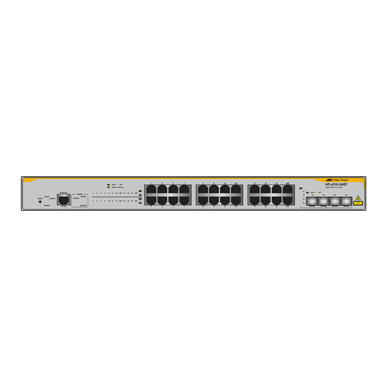
AT-x210-9GT, AT-x210-16GT, and AT-x210-24GT Switches Installation Guide Front and Back Panels Figure 2 illustrates the front panels of the AT-x210-9GT, AT-x210-16GT, and AT-x210-24GT Gigabit Ethernet Switches. ① Port LED ② 10/100/1000BASE-T Ports ③ SFP Slot LED ④ SFP Slot AT-x210-9GT LINK / AT-x210-9GT SPEED / DUPLEX... -
Page 20: Figure 3: Mode Led Toggle Button
Chapter 1: Overview Figure 3 illustrates the MODE LED toggle button on the front panel of the of the AT-x210-9GT and AT-x210-16GT Gigabit Ethernet Switches. This button changes front panel LEDs for SPEED, DUPLEX, or turns off LEDs. AT-x21 LINK / Gigabit Ethern SPEED / DUPLEX MODE... -
Page 21: Management Software
AT-x210-9GT, AT-x210-16GT, and AT-x210-24GT Switches Installation Guide Management Software The switches are shipped with the management software pre-installed. The software provides a command line interface and a GUI (Graphical User Interface) for in-band, over-the-network management. Refer to the: AlliedWare Plus Software Reference for x210 Series Switches In the unlikely event that the management software becomes corrupted or damaged on the switch, you can download the software from the Allied Telesis corporate web site and reinstall it on the switch. -
Page 22: Twisted Pair Ports
Chapter 1: Overview Twisted Pair Ports The AT-x210-9GT, AT-x210-16GT, and AT-x210-24GT Layer 2 Gigabit Ethernet Switches feature 9, 16, and 24 twisted pair ports, respectively. All ports are 10Base-T, 100Base-TX, and 1000Base-T compliant. You can set the port speeds and duplex modes either automatically with IEEE 802.3u Auto-Negotiation or manually with the management software. -
Page 23: Leds
AT-x210-9GT, AT-x210-16GT, and AT-x210-24GT Switches Installation Guide LEDs There are four types of LEDs on the AT-x210 switches: “POWER/FAULT/STANDBY LEDs” on page 13 “10Base-T/100Base-TX/1000 Base-T Link Activity LEDs” on page 15 “SFP LEDs” on page 17 POWER/ The POWER LED reports the status of AC power and is located on the left side of the front panel of the AT-x210-9GT switch. -
Page 24: Figure 6: Fault Led On At-X210-9Gt
The switch is receiving AC input power and is operating normally 6 flashes in Flashing indicates the switch is overheating. 2 seconds Contact Allied Telesis for support and advice. Steady Indicates the system is experiencing failure. Green Figure 7. FAULT LED on AT-x210-16GT Table 3 describes the functions for the STANDBY LED for the AT-x210- 9GT and AT-x210-16GT switches. -
Page 25: 10Base-T/100Base-Tx/1000 Base-T Link Activity Leds
AT-x210-9GT, AT-x210-16GT, and AT-x210-24GT Switches Installation Guide 10Base-T/ The Link Activity (L/A) LEDs provide information about the 10Base-T/ 100Base-TX/1000Base-T ports. 100Base-TX/1000 Base-T Link AT-x210-9GT Link/Activity and Speed LEDs Activity LEDs The AT-x210-9GT switch indicates LINK/ACT (link/activity) and SPEED/ DUPLEX (speed/duplex) with two LEDs for each port. See Figure 8. LINK / Speed (SPEEDDUPLEX) -
Page 26: Figure 9: At-X210-16Gt Link/Activity/Speed Leds
Chapter 1: Overview AT-x210-16GT Link/Activity LEDs The AT-x210-16GT switch has two LEDs per port on the front panel to indicate link, activity, duplex, and speed status. See Figure 9. LINK / SPEED / DUPLEX MODE MODE Speed and Link/Activity MODE (LINK/ACT) Figure 9. -
Page 27: Sfp Leds
AT-x210-9GT, AT-x210-16GT, and AT-x210-24GT Switches Installation Guide See Table 5 for a description for the AT-x210-16GT and AT-x210-24GT Link/Activity and Speed LEDs. Table 5. AT-x210-16GT and AT-x210-24GT LINK/ACT and SPEED/ DUPLEX LED Descriptions State Description Link/Activity The port has not established a link with a (LINK/ACT) network device, or the ecofriendly feature is enabled with the MODE LED... -
Page 28: Figure 12: At-X210-16Gt Sfp Status Leds
Chapter 1: Overview AT-x210-16GT Gigabit Ethernet Switch CLASS 1 LASER PRODUCT LINK / Speed and Link/Activity SFP LEDs Figure 12. AT-x210-16GT SFP Status LEDs The AT-x210-24GT SFP LEDs can be found on between the upper and lower SFP slots. See Figure 13. AT-x210-24GT Gigabit Ethernet Switch LINK /... -
Page 29: Power Supply
AT-x210-9GT, AT-x210-16GT, and AT-x210-24GT Switches Installation Guide Power Supply Each switch has an internal power supply with a single AC power supply socket on the back panel. To power the switch on or off, connect or disconnect the power cord provided with the switch. A power cord is supplied with the switch. - Page 30 Chapter 1: Overview...
- Page 31 AT-x210-9GT, AT-x210-16GT, and AT-x210-24GT Switches Installation Guide Chapter 2 Installation This chapter contains the following sections: “Reviewing Safety Precautions” on page 22 “Selecting a Site for the Switch” on page 24 “Cable Specifications” on page 25 “Unpacking the Switch” on page 26 “Installing the Switch on a Table or a Desktop”...
-
Page 32: Chapter 2: Installation
Chapter 2: Installation Reviewing Safety Precautions Please review the following safety precautions before you begin to install the chassis or any of its components. Note indicates that a translation of the safety statement is available in a PDF document titled Translated Safety Statements. Warning To prevent electric shock, do not remove the cover. - Page 33 AT-x210-9GT, AT-x210-16GT, and AT-x210-24GT Switches Installation Guide All Countries: Install product in accordance with local and National Electrical Codes. Circuit Overloading: Consideration should be given to the connection of the equipment to the supply circuit and the effect that overloading of circuits might have on overcurrent protection and supply wiring.
-
Page 34: Selecting A Site For The Switch
Chapter 2: Installation Selecting a Site for the Switch Observe the following requirements when choosing a site for your switch: If you plan to install the switch in an equipment rack, verify that the rack is safely secured and will not tip over. Devices in a rack should be installed starting at the bottom, with the heavier devices near the bottom of the rack. -
Page 35: Cable Specifications
AT-x210-9GT, AT-x210-16GT, and AT-x210-24GT Switches Installation Guide Cable Specifications Table 7 contains the cable specifications for the twisted pair ports. Table 7. Twisted Pair Cabling and Distances Maximum Speed Type of Cable Operating Distance 10 Mbps Standard TIA/EIA 568-B-compliant 100 m (328 ft) Category 3 or better shielded or unshielded cabling with 100 ohm impedance and a frequency of 16... -
Page 36: Unpacking The Switch
Chapter 2: Installation Unpacking the Switch To unpack the switch, perform the following procedure: 1. Remove all of the components from the shipping package. Note Store the packaging material in a safe location. You must use the original shipping material if you need to return the unit to Allied Telesis. -
Page 37: Installing The Switch On A Table Or A Desktop
AT-x210-9GT, AT-x210-16GT, and AT-x210-24GT Switches Installation Guide Installing the Switch on a Table or a Desktop You can install AT-x210-16GT and AT-x210-24GT switches on a desktop, or in a standard 19-inch equipment rack. To install AT-x210-16GT and AT- x210-24GT switches in a rack, see “Installing the Switch in an Equipment Rack”... -
Page 38: Installing The Switch In An Equipment Rack
Chapter 2: Installation Installing the Switch in an Equipment Rack Note: These instructions show you how to install an AT-x210-9GT, AT-x210-16GT or AT-x210-24GT switch in an equipment rack. Rack mount kit brackets are included with AT-x210-16GT and AT-x210-24GT switches. The AT-x210-9GT switch is installed in a rack with the optional AT-x210-9GT rack mount kit (Part Number 990-003904-00). -
Page 39: Figure 17: Mounting An At-X210-24Gt Switch In An Equipment Rack
AT-x210-9GT, AT-x210-16GT, and AT-x210-24GT Switches Installation Guide 4. Mount an AT-x210-24GT switch in a 19-inch equipment rack using four equipment rack screws (not provided with the switch). U LT U LT S TA S TA -2 3 L/ A -2 3 L/ A LI N LI N... -
Page 40: Figure 18: Attaching The Brackets Level With The Front Of An At-X210-16Gt
Chapter 2: Installation 5. For AT-x210-16GT Switches, attach the two rack mount brackets to the sides of the switch using the bracket screws that come with the unit. See the bracket position as shown in Figure 18 and Figure 19. L/ A C T S P L IN... -
Page 41: Figure 20: Mounting An At-X210-16Gt Switch In An Equipment Rack
AT-x210-9GT, AT-x210-16GT, and AT-x210-24GT Switches Installation Guide 6. Mount an AT-x210-16GT switch in a 19-inch equipment rack using the provided spacer bracket mounts with four equipment rack screws (not provided with the switch), as shown in Figure 20. U LT S TA L/ A C T S P... -
Page 42: Figure 21: Fitting Rack Mount Handles To The Brackets For An At-X210-9Gt
Chapter 2: Installation 7. For AT-x210-9GT switches, first fit the rack mount handles to the brackets using the supplied M3x6mm pan head screws, as shown below in Figure 21. Figure 21. Fitting rack mount handles to the brackets for an AT-x210-9GT 8. -
Page 43: Figure 23: Attaching Cable Tray Brackets For An At-X210-9Gt
AT-x210-9GT, AT-x210-16GT, and AT-x210-24GT Switches Installation Guide 9. Next attach the cable tray brackets for AT-x210-9GT switches, as shown below in Figure 23. Figure 23. Attaching cable tray brackets for an AT-x210-9GT 10. Mount an AT-x210-9GT switch in a 19-inch equipment rack, as shown below in Figure 24, using the screws from the rubber feet after removing these screws, as shown earlier in Figure 15. -
Page 44: Figure 25: Mounting An At-X210-9Gt Switch In An Equipment Rack
Chapter 2: Installation 11. Mount an AT-x210-9GT switch in a 19-inch equipment rack using the provided spacer bracket mounts with four equipment rack screws, as shown in Figure 25. U LT S TA L/ A LI N G ig it E th er w itc L/ A... -
Page 45: Installing Optional Sfp Transceivers
AT-x210-9GT, AT-x210-16GT, and AT-x210-24GT Switches Installation Guide Installing Optional SFP Transceivers To install an SFP transceiver, perform the following procedure: Note The transceiver can be hot-swapped; you do not need to power off the switch to install a transceiver. However, always remove the cables before removing the transceiver. -
Page 46: Figure 28: Inserting The Sfp On An At-X210-24Gt
Chapter 2: Installation 4. For an AT-x210-24GT Switch, gently slide the transceiver into the SFP slot until it clicks into place, as shown in Figure 28. 1981 Figure 28. Inserting the SFP on an AT-x210-24GT 5. For an AT-x210-16GT Switch, gently slide the transceiver into the SFP slot until it clicks into place, as shown in Figure 29. -
Page 47: Figure 30: Positioning The Sfp Handle In The Upright Position
AT-x210-9GT, AT-x210-16GT, and AT-x210-24GT Switches Installation Guide 6. Verify that the handle on the transceiver is in the upright position, as shown in Figure 30. This secures the transceiver and prevents it from being dislodged from the slot. SFP Transceiver Handle 1983 Figure 30. - Page 48 Chapter 2: Installation Note SFP transceivers are dust sensitive. Always keep the plug in the optical bores when a fiber optic cable is not installed, or when storing the SFP. When you do remove the plug, keep it for future use.
-
Page 49: Cabling The Switch
AT-x210-9GT, AT-x210-16GT, and AT-x210-24GT Switches Installation Guide Cabling the Switch Observe the following guidelines when connecting twisted pair and fiber optic cables to the ports on the switch: The connector on the cable should fit snugly into the port on the switch. - Page 50 Chapter 2: Installation The default speed setting for the ports is Auto-Negotiation. This setting is appropriate for ports connected to network devices that also support Auto-Negotiation. The default speed setting of Auto-Negotiation is not appropriate for ports connected to 10/100Base-TX network devices that do not support Auto-Negotiation and have fixed speeds.
-
Page 51: Powering On The Switch
AT-x210-9GT, AT-x210-16GT, and AT-x210-24GT Switches Installation Guide Powering On the Switch To power on the AT-x210-24GT, AT-x210-16GT, or AT-x210-9GT switch, perform the following procedure: 1. Plug the power cord into the AC power connector, as shown in Figure 32 on the back of an AT-x210-16GT Switch. Power cable hook Power cable hook mount Figure 32. - Page 52 Chapter 2: Installation Warning Power cord is used as a disconnection device. To de-energize equipment, disconnect the power cord. Pluggable Equipment. The socket outlet shall be installed near the equipment and shall be easily accessible. 4. Verify that the POWER LED is green. If the LED is OFF, see Chapter 3, “Troubleshooting”...
-
Page 53: Monitoring The Initialization Processes
/ /______\ \ \_ __/ /| ______ | | ______ | \ ____ / /______/\____\ \/ /____________/ Allied Telesis Inc. AlliedWare Plus (TM) v5.4.3 Current release filename: x210-5.4.3.rel Original release filename: x210-5.4.3.rel Built: Tue Jul 9 18:20:42 NZST 2013 by: maker@maker04-build Mounting static filesystems... -
Page 54: Figure 35: Switch Initialization Messages (Continued)
Chapter 2: Installation Starting base/loopback... Starting base/sysctl... Received event poefw.done Starting base/portmapper... Received event syslog.done Starting base/reboot-stability... Starting base/autofs-card... Checking system reboot stability... Starting base/cron... Starting base/appmond... Starting hardware/openhpi... Starting hardware/timeout... Starting base/inet... Starting base/modules... Received event modules.done Received event board.inserted Received event hardware.done Starting network/startup... -
Page 55: Figure 36: Switch Initialization Messages (Continued)
AT-x210-9GT, AT-x210-16GT, and AT-x210-24GT Switches Installation Guide Assigning Active Workload to HA processes: hsl, nsm, rmond, sflowd, vrrpd, irdpd, lacpd lldpd, loopprotd, mstpd, authd, epsrd, imi, imiproxyd Received event network.activated Loading default configuration Warning: flash:/default.cfg does not exist, loading factory defaults. done! Received event network.configured awplus login:... - Page 56 Chapter 2: Installation...
-
Page 57: Chapter 3: Troubleshooting
Troubleshooting This chapter contains information on how to troubleshoot the switch if a problem occurs. Note For further assistance, please contact Allied Telesis Technical Support at www.alliedtelesis.com/support. The POWER LED on the front of the switch is off. Problem 1: The unit is not receiving power. - Page 58 Chapter 3: Troubleshooting cable: Category 3 or better for 10 Mbps operation and Category 5 and Category 5E for 100 and 1000 Mbps operation. Note A 1000Base connection may require five to ten seconds to establish a link. The LINK/ACT LED for an SFP transceiver is off. Problem 3: The fiber optic port on the transceiver is unable to establish a Solutions:...
- Page 59 AT-x210-9GT, AT-x210-16GT, and AT-x210-24GT Switches Installation Guide A port’s LINK/ACT LED is blinking. Problem 5: The link between the port and the network device is intermittent. Solutions: Try the following: Connect another network device with a different cable to the port. If the Link LED remains steady on, then the problem is with the original cable or the network device.
- Page 60 Chapter 3: Troubleshooting...
- Page 61 AT-x210-9GT, AT-x210-16GT, and AT-x210-24GT Switches Installation Guide Appendix A Technical Specifications...
-
Page 62: Physical Specifications
Appendix A: Technical Specifications Physical Specifications Dimensions Table 8. Chassis Dimensions Model W x D x H mm (in) AT-x210-9GT 263 mm x 179 mm x 38 mm (10.35 in x 7.05 in x 1.50 in) AT-x210-16GT 341 mm x 210 mm x 44 mm (13.42 in x 8.26 in x 1.73 in) AT-x210-24GT 440 mm x 210 mm x 44 mm... -
Page 63: Power Specifications
AT-x210-9GT, AT-x210-16GT, and AT-x210-24GT Switches Installation Guide Power Specifications Input Supply Voltage - 100-240 VAC, 50 - 60 Hz Table 11. Power Specifications AT-x210-9GT 12 W AT-x210-16GT 19 W AT-x210-24GT 28 W Electrical Safety and Electromagnetic Emissions Certifications Table 12. Safety and Electromagnetic Emissions Certifications RFI Emissions EN 55022:2010 EN 61000-3-2:2006+A1:2009+A2:2009... -
Page 64: Connectors And Port Pinouts
Appendix A: Technical Specifications Connectors and Port Pinouts This section lists the connectors and connector pinouts. Figure 37 illustrates the pin layout for an RJ-45 connector and port. Figure 37. RJ-45 Connector and Port Pin Layout Table 13 lists the RJ-45 pin signals when a twisted pair port is operating in the MDI configuration. -
Page 65: Table 15. Rj-45 1000Base-T Connector Pinouts
AT-x210-9GT, AT-x210-16GT, and AT-x210-24GT Switches Installation Guide Table 15 lists the RJ-45 connector pins and their signals when a 1000Base-TX port is operating at 1000 Mbps. Table 15. RJ-45 1000Base-T Connector Pinouts Pair Signal TX and RX+ TX and RX- TX and RX+ TX and RX+ TX and RX-... - Page 66 Appendix A: Technical Specifications...
Need help?
Do you have a question about the AT-x210 Series and is the answer not in the manual?
Questions and answers