FOR-A MFR-1616 Operation Manual
Multi format routing switcher
Hide thumbs
Also See for MFR-1616:
- Operation manual (108 pages) ,
- Operation manuals (59 pages) ,
- Quick start manual (2 pages)
Table of Contents
Advertisement
Quick Links
Download this manual
See also:
Operating Manual
Advertisement
Table of Contents

Related Manuals for FOR-A MFR-1616


Summary of Contents for FOR-A MFR-1616
- Page 1 OPERATION MANUAL MFR-1616 MFR-1616R MFR-3216 MFR-3232 MFR-1616A Multi Format Routing Switcher MFR-39RU MFR-40RU MFR-18RU MFR-16RU/16RUD MFR-16RUW/32RUW MFR-GPI MFR-TALM Edition - Rev. 2...
- Page 2 Edition Revision History Edit. Rev. Date Description Section 2011/03/24 2012/01/24 Rear Panel figures and External Dimensions. 2-1-2, 2-1-4, 3, Amended TAKE function, enhanced MFR-18RU, etc. 2012/05/30 Changed alarm description. 2-1-3 RS Series compatibility option is cancelled. 1-2, 2-1-2, 9-1-1 Added LAN interface support, etc. 7, etc.
- Page 3 Precautions Important Safety Warnings [Power] Operate unit only on the specified supply voltage. Caution Disconnect power cord by connector only. Do not pull on cable portion. Do not place or drop heavy or sharp-edged objects on power cord. A damaged cord can cause fire or electrical shock hazards.
- Page 4 [Circuitry Access] Do not remove covers, panels, casing, or access the circuitry with power applied to the unit! Turn the power off and disconnect the power cord prior to removal. Internal servicing / adjustment of unit should only be performed by qualified personnel. Do not touch any parts / circuitry with a high heat factor.
- Page 5 Upon Receipt Unpacking MFR-1616 /MFR-1616R /MFR-3216 /MFR-3232 /MFR-1616A units and their accessories are fully inspected and adjusted prior to shipment. Operation can be performed immediately upon completing all required connections and operational settings. Check your received items against the packing lists below.
-
Page 6: About This Manual
Tally Manager Unit ITEM REMARKS MFR-TALM AC Adaptor AC cable DC cable retaining clip 1 set Single- or Dual-unit type Rack Mount Brackets 1 set (optional) EIA standard type Check Check to ensure no damage has occurred during shipment. If damage has occurred, or items are missing, inform your supplier immediately. -
Page 7: Table Of Contents
Table of Contents 1. Prior to Starting ........................11 1-1. Welcome .......................... 11 1-2. Features ........................... 11 2. Panel Descriptions ........................12 2-1. Main Unit .......................... 12 2-1-1. Front Panel ....................... 12 2-1-2. Rear Panel ........................ 13 2-1-3. Interfaces ........................16 2-1-4. - Page 8 5-3-3-9. TENKEY MOD....................51 5-3-3-10. TENKEY NO ....................51 5-3-3-11. SALVO CLR ....................52 5-3-3-12. BTN ASSIGN....................52 5-4. Operation Using the Menu Display (MFR-16RUD) ............54 5-4-1. Crosspoint Switching ....................54 5-4-2. Button Assignment Change ..................55 5-5. Setup Menu (MFR-39RU) ....................57 5-5-1.
- Page 9 7-3. Control Command ......................81 8. Troubleshooting ........................83 9. Specifications and Dimensions ....................84 9-1. Unit Specifications ......................84 9-1-1. MFR-1616/MFR-1616R/MFR-3216/MFR-3232 ............84 9-1-2. MFR-1616A ......................85 9-1-3. MFR-39RU ........................ 85 9-1-4. MFR-40RU ........................ 86 9-1-5. MFR-18RU ........................ 86 9-1-6.
-
Page 11: Prior To Starting
FOR-A provides a wide range of products, from basic support units to complex system controllers, which have been increasingly joined by products for computer video based systems. Whatever your needs, talk to your FOR-A representative. We will do our best to be of continuing service to you. -
Page 12: Panel Descriptions
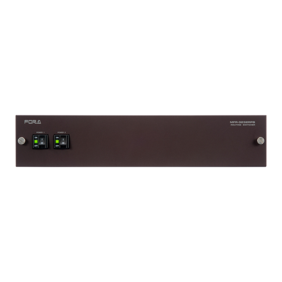
2. Panel Descriptions 2-1. Main Unit 2-1-1. Front Panel MFR-1616 / MFR-1616A MFR-1616 ROUTING SWITCHER POWER * The above figure is MFR-1616. MFR-1616R / MFR-3216 / MFR-3232 MFR-1616R ROUTING SWITCHER POWER 1 POWER 2 * The above figure is MFR-1616R. -
Page 13: Rear Panel
2-1-2. Rear Panel MFR-1616 SERIAL REF IN PC-LAN MFR-LAN ALARM MFR-1616R TO RS REF IN ALARM M FR -LAN (CPU2) SERIAL PC-LAN M FR -LAN (CPU1) SDI IN SDI OUT MFR-3216 TO RS REF IN ALARM M FR-L AN(C PU2) - Page 14 *1 The MFR-LAN/MFR-LAN(CPU1, 2) connector may be labeled as TO RU, and the PC-LAN connector as TO PC on units shipped before Sep. 16, 2011. *2 The SERIAL connector is set to RS-232C as factory default. Consult your FOR-A reseller if you wish to change the setting.
- Page 15 IMPORTANT When using the MFR-SRCPU, be sure to connect both MFR-LAN(CPU1) and MFR-LAN(CPU2) connectors to a LAN interface. See the separate MFR SERIES Web-based Control Operation Manual for more information on MFR-SRCPU.
-
Page 16: Interfaces
2-1-3. Interfaces SERIAL Connector (9-pin D-sub, male) RS-232C or 422 interface is selectable. The factory default setting is RS-232C. Consult your FOR-A reseller if you wish to change the setting. 9-pin D-sub, male RS-232C Connector Pin Assignments Pin No. - Page 17 ALARM Connector (9-pin D-sub, female) Alarm 1 Output: Under normal operation: Pins 1 and 6 are open. In a malfunction or power-off state: Pins 1 and 6 are closed. Alarm 2 Output: Under normal operation: Pins 2 and 7 are open. In a malfunction or power-off state: Pins 2 and 7 are closed.
-
Page 18: Rs-232C / Rs-422 Selection
2-1-4. RS-232C / RS-422 Selection IMPORTANT Be sure to consult your FOR-A reseller when you wish to change the RS-232C setting to RS-422. CAUTION Do not access internal cards with the unit power ON. Always power OFF all connected units / disconnect power cords prior to accessing the interior. -
Page 19: Dip Switch Settings
Default DIP switch settings are as shown below. Rear side DIP switch settings Switch Description Used to select RS-232C/RS-422. RS-232C To change the selection, refer to (Factory default) the setting position figures on the S1, S2 right. Switch settings Be sure to change both switch RS-422 positions so that they match the... - Page 20 MFR-1616R/MFR-3216/MFR-3232 (1) Remove the 6 screws as shown below from both sides of the unit, slide the top panel toward the back of the unit, and detach the panel from the unit. (2) Change the DIP switch settings. Default DIP switch settings on the main card are as shown below.
-
Page 21: Remote Control Panel
2-2. Remote Control Panel 2-2-1. Front Panel MFR-39RU F (1), MFR-39RU REMOTE CONTROL UNIT POW ER BUSY LOCK SETUP CANCEL RESET F (2) MFR-40RU F (2) MFR-40RU REMOTE CONTROL UNIT POWER BUSY SETUP LOCK RESET MFR-18RU MFR-18RU REMOTE CONTROL UNIT POW ER BUSY SETUP... - Page 22 MFR-16RUW F (3) MFR-16RUW REMOTE CONTROL UNIT POW ER BUSY SE TUP FUNC TION LOCK RE SET MFR-32RUW F (3) MFR-32RUW REMOTE CONTROL UNIT POW ER FUNCTION BU SY SET UP LO CK RE SET Item Description Displays the power status. POWER ...
- Page 23 Color indications on the MFR-RU front panel LED color Green Orange POWER LED Normal Power alarm Writing to flash BUSY LED Normal processing memory Operation locked by Lock Operation locked by Lock Other is LOCK LED All, or locked by Lock Other Lock Local activated in own unit.
-
Page 24: Rear Panel
2-2-2. Rear Panel MFR-39RU MFR-LAN SERVICE DC12V IN MFR-40RU / MFR-18RU MFR-LAN SERVICE DC12V IN MFR-16RU / MFR-16RUD MFR-LAN DC12V IN MFR-16RUW / MFR-32RUW MFR-LAN DC12V IN Item Description Used to connect the MFR main unit MFR-LAN *1 Ethernet port (10/100BASE-TX, RJ-45) SERVICE... -
Page 25: Mfr-Gpi
2-3. MFR-GPI 2-3-1. Front Panel MFR-GPI GPI UNIT SERIAL POWER BUSY GPI 1 RESET Item Description Displays the power status. POWER See the table below for details on indications. Displays the writing status of the flash memory for backup settings. BUSY ... -
Page 26: Rear Panel
2-3-2. Rear Panel SERIAL SERVICE RATING LABEL MFR-LAN GPI 1 GPI 2 GPI 3 GPI 4 2 -DC12V IN- 1 Item Description Used to connect the MFR main unit MFR-LAN *1 Ethernet port (10/100BASE-TX, RJ-45) SERVICE Used for maintenance only. Do not use. DC12V IN 1 and 2 Used to supply 12 V DC power. -
Page 27: Interfaces (Mfr-Gpi)
2-3-3. Interfaces (MFR-GPI) GPI IN / TALLY OUT Connector (37-pin D-sub, female) Pin No. Signal Pin No. Signal GPI_IN / TALLY_OUT 01 # GPI_IN / TALLY_OUT 20 # GPI_IN / TALLY_OUT 02 # GPI_IN / TALLY_OUT 21 # GPI_IN / TALLY_OUT 03 # GPI_IN / TALLY_OUT 22 # GPI_IN / TALLY_OUT 04 # GPI_IN / TALLY_OUT 23 #... - Page 28 GPI OUT / TALLY OUT Circuit External device MFR-GPI Max. voltage: 40 V Max. current: 100 mA...
-
Page 29: Switches On The Card
OFF all connected units / disconnect power cords prior to accessing the interior. Further note that adjustments and maintenance should only be performed by qualified technical personnel familiar with FOR-A equipment. Remove two screws on both sides of the MFR-GPI to access the internal card as shown below. -
Page 30: Mfr-Talm
2-4. MFR-TALM 2-4-1. Front Panel MFR-TALM TALLY MAN AGER UNIT POWER BUSY REF IN RS-422 RESET Item Description Displays the power status. POWER See the table below for details on indications. Displays the writing status of the flash memory for backup settings. BUSY ... -
Page 31: Rear Panel
2-4-2. Rear Panel RS-422 DC12V IN PC-LAN MFR-LAN REF IN SER. NO. Name Description Used to connect to a PC or other external unit. PC-LAN An Ethernet port (10/100BASE-TX RJ-45) Used to connect to an MFR main unit. MFR-LAN An Ethernet port (10/100/1000BASE-T RJ-45) REF IN Used to input a reference signal (BB or Tri-level sync signal) Used to input/output GPI signals for external control. -
Page 32: System Configuration Example
3. System Configuration Example 3-1. Basic Configuration The block diagram below shows an example of the basic MFR routing system that consists of an MFR Main Unit, Remote Unit and the Web-based Control accessed from a computer. Make sure to connect both MFR-LANs (CPU1) and (CPU2) to a LAN respectively for CPU redundancy. -
Page 33: Signal Name And Tally Link System
3-2-1. Configuration Example 1 The block diagram below shows an example signal name and tally link system comprised of a FOR-A video switcher and multiviewer. To configure this system, connect the SERIAL port on an MFR main unit or SERIAL 1 to 4 on an MFR-GPI unit to the video switcher's serial port. - Page 34 Transmitting Signal Name and Tally Data The figure below shows the routing of signal name and tally data. Set each serial port following the table on this page using the MFR Web Control and on the switcher. Each tally information setting should be performed in the [Web-based Control: Tally System Settings page].
-
Page 35: Configuration Example 2
The block diagram below shows an example signal name and tally link system comprised of a FOR-A video switcher and multiviewer using an MFR-TALM unit. The MFR-TALM is specifically designed to perform the task of tally data computation, which is ordinarily undertaken by the MFR main unit, to accelerate the computation. - Page 36 Transmitting Signal Name and Tally Data The figure below shows an example signal name and tally data routing system using the MFR-TALM. Signal name data Tally and name data Switcher's tally data Router's tally and name data Each serial port should be set as shown in the table below in the relevant page of the MFR-TALM Web-based Control accessed from "http://192.168.1.62"...
- Page 37 TCP/IP Setting Open the [MFR-TALM Web-based Control: Port Settings page] and perform port settings under TCP/IP Port. [Port Settings] - [TCP/IP Port] Port Menu Access IP Address Port Function Method Web-based Control (MV TCP/IP TSL UMD protocol Client IP address) port number) V5.0 Tally out [TALM Settings]...
-
Page 38: Function / Operation Chart
● ● Alarm indication *1 This function is supported only for the MFR-5000. MFR-1616, MFR-1616R, MFR-3216, MFR-3232, and MFR-1616A are not supported. *2 MFR-18RU is supported for crosspoint switching using destination buttons in the setting mode selected in the mode menu. -
Page 39: Remote Control Panel Operation
5. Remote Control Panel Operation 5-1. Basic Operation This section describes basic operation of the remote control panel and how to set and execute various functions. 5-1-1. Buttons 1) Assign functions to buttons (change assignments) To use buttons on the remote control panel, assign functions to the buttons in the [Web-based Control: Assign Function page]. -
Page 40: Page Function
5-1-2. Page Function A set of button assignments on a remote control panel can be saved and recalled as a page. Therefore, all or multiple panel buttons can change their function simultaneously by loading a page with a single button press. Pages can be changed either by pressing PAGE buttons or by using the control knob in Page mode. -
Page 41: Control Knob
MFR-16RUW MFR-16RUW REMOTE CONTROL UNIT POW ER FUNC TION BUSY SE TUP LOCK RE SET Group A Group B Group C MFR-32RUW MFR-32RUW REMOTE CONTROL UNIT POW ER FUNCTION BU SY SET UP LO CK RE SET Group A Group B Group C ... - Page 42 The Control knob can be disabled or enabled in the [Web-based Control: RU Settings page]. To enable/disable the Control knob (1) Open the Web-based Control on your browser. (2) Click a remote control unit to display the menu tree. Select the RU Settings page. (3) Select Enable or Disable under Control (Dest/Src/Level/Page/Settings Selector).
-
Page 43: Function Buttons
5-2. Function Buttons Functions that are assignable to Remote control panel buttons are as shown in the below table. Normally, functions are assigned via Web-based Control. (See "Assign Function" in Web-based Control) MFR-39RU menu display is enabled to assign functions. (See 5-3-3-12. “BTN ASSIGN.") MFR-16RUD can locall assign functions using the displa . - Page 44 Button Function Description Reference indication LOCK Allows you to enable or disable Lock Other/All for 6-3-2 current destinations. Button indications Top: LOCK OTHER Bottom: LOCK ALL Allows you to enable or disable Lock Other/All for a specific destination. * Button indications Top: LOCK OTHER a destination (1 in this example) Bottom: LOCK ALL a destination (1 in this example) TAKE...
-
Page 45: Mode Button And Mode Menu (Mfr-39Ru/18Ru)
Destination Button LCD Indication Usually destination channel names are displayed on the LCD above the destination buttons. The MFR-18RU can also display source channel names that are selected for destinations. To display source channel names, set the menu under Display Setting in the [Web-based Control: RU Settings page]. - Page 46 Level Mode Displays the current level and its name of the remote control panel. (The name is in brackets.) The button indicates the current level and its name. LVL : 0001 [Level-1 Menu display Button LCD Page Mode Displays the page number of the current assignment of the remote control panel buttons.
- Page 47 Setting Mode In MFR-39RU Displays available menu settings that can be changed using the control knob. Turn the control knob to select an item, then change the setting. The items that can be changed are highlighted. See section 5-3-3. Setting Mode Menu (MFR-39RU) for details. SETTING>DEF MODE <ENT>...
-
Page 48: Setting Mode Menu (Mfr-39Ru)
5-3-3. Setting Mode Menu (MFR-39RU) Setting Mode menu items are as shown below. Setting Mode menu items MENU indication Description Reference SETTING>DEF MODE <ENT> Allows you to change the remote control panel 5-3-3-1 start-up default mode. SETTING>DEF DEST <ENT> Allows you to change the remote control panel 5-3-3-2 start-up default destination. -
Page 49: Def Dest
5-3-3-2. DEF DEST This menu allows you to select a destination to be displayed on the menu display at the start-up of the remote control panel. SETTING>DEF DEST DEF DEST: 1<ENT> Turn the control knob to select a destination, then press the knob to confirm. IMPORTANT Do not turn off the remote control panel until the BUSY indicator, which lights orange, goes off when changing modes. -
Page 50: Dstinhibit
5-3-3-6. DSTINHIBIT This menu allows you to restrict the output change of the specific destination channel. SETTING>DSTINHIBIT DST 1 : OFF <ENT> Turn the control knob to select a destination channel, and press the knob to confirm. SETTING> DSTINHIBIT DST 1 : ON <ENT> Turn the control knob to select ON or OFF, and press the knob to confirm. -
Page 51: Name Type
5-3-3-8. NAME TYPE This menu allows you to select a name display type for the destination, source and level. SETTING>NAME TYPE DST BTN :PHY NUM <ENT> Turn the control knob to select a button group from the destination, source and level buttons. -
Page 52: Salvo Clr
5-3-3-11. SALVO CLR This menu allows you to clear a specific salvo assigned to a button. SALVO DELETE 1<ENT> Turn the control knob to select a salvo to clear, and press the knob to confirm. If any salvo is assigned, the menu display appears as shown below. SALVO DELETE (NO SALVO DATA) 5-3-3-12. - Page 53 Setting Parameters for Functions Function Parameter Note (NONE) DEST DEST:XXX (XXX: Destination Channel number) LEVEL:XXXX (XXXX: Level) SRC:XXXX (XXXX: Source Channel number) LEVEL:XXXX (XXXX: Level) DEST:XXX (XXX: Destination Channel number) LEVEL:XXXX (XXXX: Level) SRC:XXXX (XXXX: Source Channel number) LEVEL:XXXX (XXXX: Level) PAGE MODE:JUMP...
-
Page 54: Operation Using The Menu Display (Mfr-16Rud)
5-4. Operation Using the Menu Display (MFR-16RUD) The MFR-16RUD, a remote control unit with a display, allows you to select destination channels and switch crosspoints using the menu display. Function button assignments are also possible. Default Display The name of Current Destination Channel is displayed on the first line. The name of Source Channel selected for Current Destination is displayed on the second line. -
Page 55: Button Assignment Change
(3) Press ENTER to perform the crosspoint switch. The screen will return to the default display. MFR-16RUD ENTER REMOTE CONTROL UNIT PAGE A D: DST 5 LOCK PANL (HOLD 3SEC) SRC 8 CANCEL PAGE B LOCK DEST (HOLD 3SEC) 5-4-2. Button Assignment Change To change button assignments, proceed as follows: (1) Press a button while holding down ENTER. - Page 56 Assignable Function/Parameter List Function Parameter Description (NONE) None DESTINATION DESTINATION (XXX: Destination Channel number) SOURCE SOURCE YYYY (YYYY: Source Channel number) BUS D YYYY (XXX: Destination Channel number YYYY: Source Channel number) LOCK LOCAL None LOCK LOCK (XXX:OTH LOCK OTHER /ALL LOCK ALL YYY:CUR...
-
Page 57: Setup Menu (Mfr-39Ru)
5-5. Setup Menu (MFR-39RU) The SETUP button enables you to use the setup menu. The Setup menu has following sub menus. To select a submenu, turn the control knob to select and press to confirm. Setup Menu Sub-menu List Menu display Description Reference... -
Page 58: Pc-Lan[Mu]
5-5-3. PC-LAN[MU] The PC-LAN[MU] menu allows you to display the network settings for the PC-LAN port on the MU and restart the port. SETUP>PC-LAN[MU]> <ENT> Selecting NET allows you to display the network port settings. Turning the control knob allows you to scroll through all network settings. PC-LAN[MU]>IP ADDRESS 192.168.001.012 <ENT>... -
Page 59: Ru Connect
5-5-5. RU CONNECT This menu allows you to enable or disable integrated operation of connected multiple remote control panels. SETUP>RU CONNECT ENABLE:OFF<ENT> Turn the control knob to select ON or OFF, and press the knob to confirm the selection. IMPORTANT Do not turn the power of the remote control panel off before the orange BUSY lamp goes off when changing ID. -
Page 60: Setup Menu (Mfr-18Ru)
5-6. Setup Menu (MFR-18RU) The SETUP button allows you to enter Setup Menu mode, in which RU and MU PC-LAN network settings are displayed, the MU-PC LAN port can be rebooted and RU network settings can be changed. The left three buttons are used to select information to be displayed or the PC-LAN reboot. -
Page 61: Rebooting Mu Pc-Lan
(4) Repeat steps (2) and (3) to change the IP address and subnet mask. (5) When number values are changed, the SAVE button will blink. Press and hold down SAVE to confirm changes. The Remote Control Unit will automatically restart. To cancel the process, display another information without pressing SAVE. -
Page 62: Setup Menu (Other Remote Control Units)
5-7. Setup Menu (Other Remote Control Units) The SETUP button changes the RU to Setup Menu mode, which allows you to display RU and MU PC-LAN network settings, reboot the MU PC-LAN port and change the RU network settings To exit Setup Menu mode, press the SETUP button again. ... -
Page 63: Displaying Network Settings
5-7-1. Displaying Network Settings (1) In Setup Menu mode, press a button shown in the table below to display the desired network setting . Note that button locations vary depending on remote control units. Button operation LAN port Display Info. Press D. -
Page 64: Changing The Ru Network Settings
5-7-2. Changing the RU Network Settings The RU IP address and subnet mask can be changed as shown in the procedure below. In the following procedure changes the MFR-16RU IP address from "192.168.1.100" to "192.168.1.101." Button locations vary depending on remote control units. Refer to the previous page for button locations of other remote control units. -
Page 65: Rebooting Mu Pc-Lan
5-7-3. Rebooting MU PC-LAN (1) Press Button C in Setup Menu mode. (2) Press and hold down Button K. Button L (EXEC button) will blink. (3) Press and hold down Button L. Buttons I will blink during rebooting. The buttons will turn off when the reboot is complete. -
Page 66: Multi-Panel Operation
5-8. Multi-Panel Operation 5-8-1. Outline Multiple remote control panels can be connected to build a large control panel. NOTE Up to 5 remote control units can be linked together in Multi-panel Operation mode. (Ex.) To build a 96 x 96 maximum control system: Units to use: MFR-40RU x 4, and MFR-39RU x 1 Configuration: Destination button assignments to: MFR-40RU x 2 and a part of MFR-39RU... -
Page 67: Enabling Multi-Panel Operation
5-8-2. Enabling Multi-Panel Operation Multi-panel operation can be enabled in the Setup menu or in the [Web-based Control: RU Settings page]. The procedure to enable multi-panel operation in the Setup menu is as shown below. (Supported only by MFR-39RU) Step Description Press the SETUP button to open the Setup menu. -
Page 68: Crosspoint Control
6. Crosspoint Control 6-1. One Crosspoint Switching There are two ways of switching crosspoints: Switching a crosspoint one at a time, or switching multiple crosspoints simultaneously. This section describes the switching of one crosspoint. 6-1-1. One Crosspoint Switching by X-Y Setting A crosspoint can be switched by using the destination and source buttons on the remote control panel. -
Page 69: Skip-Fwd / Skip-Bwd
6-1-1-1. SKIP-FWD / SKIP-BWD The SKIP-FWD button allows you to skip the set destination number or source channels forward to select the current one. The SKIP-BWD button allows you to skip channels backward. In Destination or Source mode, the set number of channels is skipped. In Level, Page or Setting mode, these buttons are inoperable. -
Page 70: A Crosspoint Switching Using A Bus Button
Category buttons: Allows you to select a category to select a channel from using the numeric keypad. - TENKEY CANCEL: Allows you to exit TENKEY mode. The entered number is indicated on the button when "SETTING > TENKEY MOD (INPUT MODE)" is set to ENTER. - PAGE UP / DOWN: Allows you to change pages for the category buttons. -
Page 71: Chop Function
6-1-3. CHOP Function The CHOP function allows you to alternate 2 images to compare the images. Enabling the CHOP function (1) Press one of 2 source buttons (source A) to compare. (2) While holding down the source button, press and release another source button (source Images of source A and B alternate. - Page 72 Ex. 2: To use the TAKE button assigned to Direct mode Step Description In Direct mode, the Take function is always enabled. Select a crosspoint by selecting a destination button and source button. The selected buttons will blink. * To switch multiple crosspoints, repeat the procedure. After completing the crosspoint selection, press the blinking TAKE button to switch the crosspoint/s.
-
Page 73: Simultaneous Crosspoint Switching
6-2. Simultaneous Crosspoint Switching The simultaneous crosspoint switching function allows you to simultaneously switch multiple crosspoints by the press of one button. There are two ways to do so. One is the Salvo function which performs the switching by recalling the pre-assigned crosspoints. The other is the Take function which allows you to assign and switch multiple crosspoints simultaneously. -
Page 74: Simultaneous Switching By The Take Function
After completing the crosspoints assignments, press the SALVO button again. The menu display appears as shown below. SALVO STORE 1 (NEW) <ENT> To add crosspoints to an existing salvo, select a salvo number by turning the control knob. Salvo numbers to which no crosspoints are assigned are indicated with (NEW). Turn the control knob to select a number, and press the knob to confirm the selection. -
Page 75: Lock
6-3. Lock Function operation and crosspoint changes can be disabled by the Lock function. LOCK Function The Lock function is a function that inhibits the use of function buttons or crosspoint changes. There are three types of Lock functions. Inhibits source channel and function Inhibits operation on own unit... -
Page 76: Lock Other / Lock All
6-3-2. LOCK OTHER / LOCK ALL The Lock Other and Lock All functions disable crosspoint changes for current destination channels to all other units or all units including the unit that enabled the Lock function. Lock functions can be disabled only from the unit that enabled the function. In multi-panel operation, lock functions can be disabled from any remote control panel in the operation system. -
Page 77: Operation Preview Function
6-4. Operation Preview Function The Operation Preview function allows you to set an output to be used for the preview. (ex.) When pressing a source button on the remote control panel for setting a simultaneous crosspoint switch, the selected source will be output to the preview output. Then you can check source images to be assigned to the simultaneous crosspoint switch before pressing TAKE. -
Page 78: Level Control
6-5. Level Control Generally, routing switchers control crosspoints according to the signal types such as video, audio, time codes, and VCR control. To control switchers, level numbers are used to identify which type of signal to control. Video signal Source channel Crosspoint Video signal Destination channel... -
Page 79: Level Indication On The Remote Control Panel
6-5-1. Level Indication on the Remote Control Panel The MFR main unit and the remote control panel can control signals on multiple levels at the same time. The remote control panel indicates the current level(s) by hexadecimal numbers in the menu display and on the LCD. (ex.1) If all levels 1 through 8 are enabled, the indication is “00FF."... -
Page 80: Serial / Lan Command Control
7. Serial / LAN Command Control 7-1. Serial Interface Crosspoint switchover and tally output can be controlled via the SERIAL ports on the MFR Series main unit or MFR GPI. 7-2. LAN Interface The MFR Series main unit is able to connect to a third-party automatic control system via the RJ-45 port (PC-LAN port). -
Page 81: Control Command
7-3. Control Command Serial and LAN interfaces for Crosspoint Remote Control use control commands. Crosspoint information command Command Range Description <Lvl> 0 - 7 Allows you to specify the level to switch the crosspoint. * When switching one crosspoint. <Lvls>... - Page 82 IMPORTANT -All values are converted to hexadecimal notation. (e.g. Source 16 is represented as <Src> F) Also, the carriage return (ASCII: 0D) is required at the end of all commands. -Send the next command after receiving a prompt (>). The command expiration time (maximum wait time for response) for a short command is 1 second.
-
Page 83: Troubleshooting
8. Troubleshooting If any of the following problems occur during operation of your MFR-1616 MFR-1616R / MFR-3216 / MFR3232, proceed as indicated below to see if the problem can be corrected before assuming a unit malfunction has occurred. IMPORTANT If the problem is not corrected by performing the procedures below, turn the unit off and then on again. -
Page 84: Specifications And Dimensions
9. Specifications and Dimensions 9-1. Unit Specifications 9-1-1. MFR-1616/MFR-1616R/MFR-3216/MFR-3232 MFR-1616 MFR-1616R MFR-3216 MFR-3232 Video Formats 3G HD: 1080/60p, 1080/59.94p, 1080/50p HD: 1080/60i, 1080/59.94i, 1080/50i, 1080/30p, 1080/30PsF, 1080/29.97p, 1080/29.97PsF, 1080/23.98p, 1080/23.98PsF, 1080/25p, 1080/25PsF, 1080/24PsF, 1080/24p, 720/60p, 720/59.94p, 720/50p SD: 525/60, 625/50... -
Page 85: Mfr-1616A
9-1-2. MFR-1616A Inputs x Outputs 16 stereo pairs (32 channels) × 16 stereo pairs (32 channels) Audio Inputs AES/EBU: 1.0Vp-p Unbalanced 75Ω BNC x 16 Audio Outputs AES/EBU:1.0Vp-p±10% Unbalanced 75Ω BNC x 16 Sampling Frequency 32kHz to 96kHz Reference Input BB: NTSC: 0.429 Vp-p/PAL: 0.45 Vp-p or Tri-level sync: ±0.3 Vp-p 75Ω... -
Page 86: Mfr-40Ru
9-1-4. MFR-40RU Buttons/Colors 40 buttons (3 colors: red/green/orange), user assignable Number of Max. 128 units (including Main, Remote and GPI units) Connections Interfaces MFR-LAN 10/100BASE-TX RJ-45 x 1 (For connection to MU. A network hub required for multiple unit configuration.) SERVICE RS-232C 9-pin D-sub (male) x 1 (for maintenance) Temperature... -
Page 87: Mfr-16Ru/16Rud
9-1-6. MFR-16RU/16RUD Buttons/Color 16 buttons (1 color: green), user assignable Menu Display (Max. 16 characters x 2 lines) (MFR-16RUD only) Number of Connection Max. 128 (including Main, Remote and GPI units) Interfaces MFR-LAN 10/100BASE-TX RJ-45 x 1 (For connection to MU. A network hub required for multiple unit configuration.) Temperature 0°C to 40°C... -
Page 88: Mfr-Gpi
9-1-9. MFR-GPI Number of Max. 128 (including Main, Remote and GPI units) Connection Interface MFR-LAN 10/100BASE-TX RJ-45 x 1 (Ethernet hub is needed for Main and multiple unit connections.) SERVICE RS-232C: 9-pin D-sub (male) x 1 (for maintenance) GPI IN 37-pin D-sub (female) x 4 /TALLY OUT 128-input/output (user assignable) -
Page 89: External Dimensions
9-2. External Dimensions 9-2-1. MFR-1616 (All dimensions in mm.) MFR-1616 ROUTING SWITCHER POWER 9-2-2. MFR-1616R (All dimensions in mm.) MFR-1616R R OU TING SW ITC HER POW ER 1 POW ER 2... -
Page 90: Mfr-3216
9-2-3. MFR-3216 (All dimensions in mm.) MFR-3216 R OU TING SW ITC HER POW ER 1 POW ER 2 9-2-4. MFR-3232 (All dimensions in mm.) MFR-3232 R OU TING SW ITC HER POW ER 1 POW ER 2... -
Page 91: Mfr-1616A
9-2-5. MFR-1616A (All dimensions in mm.) MFR-1616A ROUTING SWITCHER POWER... -
Page 92: Mfr-39Ru
9-2-6. MFR-39RU (All dimensions in mm.) MFR-39RU REM OTE CONTROL UNIT POW ER BUSY LOCK SETUP CANCEL RESET MFR-39RU REM OTE CONTROL UNIT POW ER BUSY LOCK SETUP CANCEL RESET * The panel buttons can be fitted within the rack by sliding the rack ears forward to attach as shown in the bottom figure above. -
Page 93: Mfr-18Ru
9-2-8. MFR-18RU (All dimensions in mm.) MFR-18RU REMOTE CONTROL UNIT POWER BUSY SETUP LOCK RESET MFR-18RU REMOTE CONTROL UNIT POWER BUSY SETUP LOCK RESET * The panel buttons can be fitted within the rack by sliding the rack ears forward to attach as shown in the bottom figure above. -
Page 94: Mfr-16Rud
9-2-10. MFR-16RUD (All dimensions in mm.) MFR-16RUD ENTER R EMOTE C ON TR OL U N IT P A G E A POW ER LO CK P A NL (HOLD 3SEC) BU SY SETU P CAN CEL P A G E B LOC K R ESET LO CK DE S T... -
Page 95: Mfr-32Ruw
9-2-12. MFR-32RUW (All dimensions in mm.) MFR-32RUW REMOT E CONTRO L UNIT POWER BUSY SETUP FUNC TION LOCK RESET 9-2-13. MFR-GPI (All dimensions in mm.) MFR-GPI GPI UNIT MFR-GPI GPI UNIT SERIAL SERIAL POWER BUSY RESET POWER BUSY RESET MFR-GPI GPI UNIT SERIAL POWER... -
Page 96: Mfr-Talm
9-2-14. MFR-TALM (All dimensions in mm.) MFR-TALM TALLY MANAGER UNIT POWER BUSY REF IN RS-422 RESET 21.2 169.6 21.2 If attaching the rack mount brackets (Dual / Single) MFR-TALM TALLY MANAGER UNIT POWER BUSY REF IN RS-422 RESET MFR-TALM MFR-TALM TALLY MAN AGER UNIT TALLY MAN AGER UNIT... -
Page 97: Button Label Template For Mfr-40Ru/16Ru/16Rud
Button Label Template for MFR-40RU/16RU/16RUD 12.8 mm 12.8 mm Button Label Template for MFR-39RU 10.2 mm 10.2 mm... -
Page 99: Button Label Template For Mfr-16Ruw/32Ruw
Button Label Template for MFR-16RUW/32RUW 9.8 mm 9.8 mm... - Page 101 Warning This equipment has been tested and found to comply with the limits for a Class A digital device, pursuant to Part 15 of FCC Rules. These limits are designed to provide reasonable protection against harmful interference when the equipment is operated in a commercial environment. This equipment generates, uses, and can radiate radio frequency energy and, if not installed and used in accordance with the instruction manual, may cause harmful interference to radio communications.
- Page 102 FOR-A America East Coast Office 2 Executive Drive, Suite 670, Fort Lee Executive Park, Fort Lee, NJ 07024, USA Phone: +1-201-944-1120 Fax : +1-201-944-1132 FOR-A America Distribution & Service Center 2400 N.E. Waldo Road, Gainesville, FL 32609, USA Phone: +1-352-371-1505 Fax: +1-352-378-5320...
Need help?
Do you have a question about the MFR-1616 and is the answer not in the manual?
Questions and answers