FOR-A MFR-1616 Operation Manuals
Multi format routing switcher.
Hide thumbs
Also See for MFR-1616:
- Operation manual (108 pages) ,
- Quick start manual (2 pages) ,
- Operation manual (105 pages)
Table of Contents
Advertisement
Quick Links
Download this manual
See also:
Operating Manual
Advertisement
Table of Contents

Subscribe to Our Youtube Channel
Related Manuals for FOR-A MFR-1616


Summary of Contents for FOR-A MFR-1616
- Page 1 OPERATION MANUAL MFR-1616/1616R/1616A MFR-3216/3216RPS MFR-3232/3232RPS Multi Format Routing Switcher MFR-GPI MFR-TALM Edition - Rev.2...
- Page 2 Edition Revision History Edit. Rev. Date Description Section 2011/03/24 2012/01/24 Rear Panel figures and External Dimensions. 2-1-2, 2-1-4, 3, Amended TAKE function, enhanced MFR-18RU, etc. 2012/05/30 Changed alarm description. 2-1-3 RS Series compatibility option is cancelled. 1-2, 2-1-2, 9-1-1 Added LAN interface support, etc. 7, etc.
- Page 3 Main Unit Firmware Version (*1) GUI Version Supported Supported Hardware Feature (*2) MFR-1616/1616R/3216/3232 MFR-1616A 1.22 or higher 1.23 or higher 1.61 or higher MFR-64RUW Main Unit Link (*1) Click [Primary CPU] in the [Web-based Control: System Settings- MU Info page] to see your version number under Firmware Version.
- Page 4 Precautions Important Safety Warnings [Power] Operate unit only at the specified supply voltage. Caution Disconnect the power cord via the power plug only. Do not pull on the cable portion. Do not place or drop heavy or sharp-edged objects on the power cord. A damaged cord can cause fire or electrical shock hazards.
- Page 5 [Circuitry Access] Do not remove covers, panels, casing, or access the circuitry with power applied to the unit. Turn the power off and disconnect the power cord prior to removal. Internal servicing / adjustment of unit should only be performed by qualified personnel. Do not touch any parts / circuitry with a high heat factor.
- Page 6 Upon Receipt Unpacking MFR-1616/ MFR-1616R/ MFR-1616A/ MFR-3216/ MFR-3216RPS/ MFR-3232/ MFR-3232RPS units and their accessories are fully inspected and adjusted prior to shipment. Operation can be performed immediately upon completing all required connections and operational settings. Check your received items against the packing lists below.
-
Page 7: About This Manual
Check Check to ensure no damage has occurred during shipment. If damage has occurred, or items are missing, inform your supplier immediately. About This Manual This manual is intended to help the user easily operate this product and make full use of its functions during operation. -
Page 8: Table Of Contents
4-3-7. Video Format Commands (11) ................... 48 5. Troubleshooting ......................... 49 6. Specifications and Dimensions ....................50 6-1. Unit Specifications ......................50 6-1-1. MFR-1616/1616R/3216/3216RPS/3232/3232RPS ............ 50 6-1-2. MFR-1616A ......................... 51 6-1-3. MFR-GPI ........................51 6-1-4. MFR-TALM ........................52 6-2. External Dimensions ......................53... - Page 9 6-2-2. MFR-1616R ......................... 53 6-2-3. MFR-3216 ........................54 6-2-4. MFR-3232 ........................54 6-2-5. MFR-1616A ......................... 55 6-2-6. MFR-3216RPS ......................55 6-2-7. MFR-3232RPS ......................56 6-2-8. MFR-GPI ........................56 6-2-9. MFR-TALM ........................57...
-
Page 10: Prior To Starting
MFR-3216RPS / MFR-3232 / MFR-3232RPS Multi Format Routing Switcher (hereafter called MFR main unit) you have entered the world of FOR-A and its many innovative products. Thank you for your patronage and we hope you will turn to FOR-A products again and again to satisfy your video and audio needs. -
Page 11: Panel Descriptions
2. Panel Descriptions 2-1. Main Unit 2-1-1. Front Panel MFR-1616 / MFR-1616A MFR-1616 ROUTING SWITCHER POWER * The above figure is MFR-1616. M(2) MFR-1616R / MFR-3216 / MFR-3232 MFR-1616R ROUTING SWITCHER POWER 1 POWER 2 * The above figure is MFR-1616R. -
Page 12: Rear Panel
2-1-2. Rear Panel MFR-1616 REF IN SERIAL PC-LAN MFR-LAN ALARM MFR-1616R TO RS REF IN ALARM M FR -LAN (CPU2 ) SERIAL PC-LAN M FR -LAN (CPU1 ) SDI IN SDI OUT MFR-3216 / MFR-3216RPS TO RS... - Page 13 *1 The MFR-LAN/MFR-LAN(CPU1, 2) connector may be labeled as TO RU, and the PC-LAN connector as TO PC on units shipped before Sep. 16, 2011. *2 The SERIAL connector is set to RS-232C as factory default. Consult your FOR-A reseller if you wish to change the setting.
-
Page 14: Interfaces
2-1-3. Interfaces SERIAL Connector (9-pin D-sub, male) RS-232C or 422 interface is selectable. The factory default setting is RS-232C. Consult your FOR-A reseller if you wish to change the setting. 9-pin D-sub, male RS-232C Connector Pin Assignments Pin No. - Page 15 ALARM Connector (9-pin D-sub, female) Alarm 1 Output: Under normal operation: Pins 1 and 6 are open. In a malfunction or power-off state: Pins 1 and 6 are closed. Alarm 2 Output: Under normal operation: Pins 2 and 7 are open. In a malfunction or power-off state: Pins 2 and 7 are closed.
-
Page 16: Rs-232C / Rs-422 Selection
2-1-4. RS-232C / RS-422 Selection IMPORTANT Be sure to consult your FOR-A reseller when you wish to change the RS-232C setting to RS-422. CAUTION Do not access internal cards with the unit power ON. Always power OFF all connected units / disconnect power cords prior to accessing the interior. -
Page 17: Dip Switch Settings
Default DIP switch settings are as shown below. Rear side DIP switch settings Switch Description Used to select RS-232C/RS-422. RS-232C To change the selection, refer to (Factory default) the setting position figures on the S1, S2 right. Switch settings Be sure to change both switch RS-422 positions so that they match the... - Page 18 MFR-1616R / MFR-3216 / MFR-3216RPS / MFR-3232 / MFR-3232RPS (1) For MFR-1616R / MFR-3216 / MFR-3232 units, remove the 6 screws as shown below from both sides of a unit, slide the top panel toward the back of the unit, and detach the panel from the unit.
-
Page 19: Mfr-Gpi
2-2. MFR-GPI 2-2-1. Front Panel MFR-GPI GPI UNIT SERIAL POWER BUSY GPI 1 RESET Item Description Displays the power status. POWER See the table below for details on indications. Displays the writing status of the flash memory for backup settings. BUSY ... -
Page 20: Rear Panel
2-2-2. Rear Panel SERIAL SERVICE RATING LABEL 2 -DC12V IN- 1 MFR-LAN GPI 1 GPI 2 GPI 3 GPI 4 Item Description Used to connect the MFR main unit MFR-LAN *1 Ethernet port (10/100BASE-TX, RJ-45) SERVICE Used for maintenance only. Do not use. DC12V IN 1 and 2 Used to supply 12 V DC power. -
Page 21: Interfaces (Mfr-Gpi)
2-2-3. Interfaces (MFR-GPI) GPI IN / TALLY OUT Connector (37-pin D-sub, female) Pin No. Signal Pin No. Signal GPI_IN / TALLY_OUT 01 # GPI_IN / TALLY_OUT 20 # GPI_IN / TALLY_OUT 02 # GPI_IN / TALLY_OUT 21 # GPI_IN / TALLY_OUT 03 # GPI_IN / TALLY_OUT 22 # GPI_IN / TALLY_OUT 04 # GPI_IN / TALLY_OUT 23 #... - Page 22 GPI OUT / TALLY OUT Circuit MFR-GPI External device Max voltage: 40V Max current: 100mA 10Ω * The voltage is about 0.9 V when turned-on.
-
Page 23: Switches On The Card
OFF all connected units / disconnect power cords prior to accessing the interior. Further note that adjustments and maintenance should only be performed by qualified technical personnel familiar with FOR-A equipment. Remove two screws on both sides of the MFR-GPI to access the internal card as shown below. -
Page 24: Mfr-Talm
2-3. MFR-TALM 2-3-1. Front Panel MFR-TALM TALLY MAN AGER UNIT POWER BUSY REF IN RS-422 RESET Item Description Displays the power status. POWER See the table below for details on indications. Displays the writing status of the flash memory for backup settings. BUSY ... -
Page 25: Rear Panel
2-3-2. Rear Panel RS-422 DC12V IN PC-LAN MFR-LAN REF IN SER. NO. Name Description Used to connect to a PC or other external unit. PC-LAN An Ethernet port (10/100BASE-TX RJ-45) Used to connect to an MFR main unit. MFR-LAN An Ethernet port (10/100/1000BASE-T RJ-45) REF IN Used to input a reference signal (BB or Tri-level sync signal) Used to input/output GPI signals for external control. -
Page 26: System Configuration Example
3. System Configuration Example 3-1. Basic Configuration The block diagram below shows an example of the basic MFR routing system that consists of an MFR Main Unit, Remote Unit and the Web-based Control accessed from a computer. Make sure to connect both MFR-LANs (CPU1) and (CPU2) to a LAN respectively for CPU redundancy. -
Page 27: Main Unit Linking
Refer to Firmware / Software Versions and Supported Hardware / Features (p. 3) for details on the supported version. 3-2-1. Parallel Link System Example The system example below shows video and audio links using a Parallel Link system composed of MFR-1616 and MFR-1616A units. MFR-1616 (Master) REF IN... -
Page 28: Expanded Matrix System Example
1) Connect all devices in the MFR system as shown in the figure in the previous page. 2) Power on the MFR-1616, Remote Control unit and computer. (Do not power on the MFR-1616A.) Set the IP address for the Remote Control Unit (①) and computer (④). -
Page 29: Signal Name And Tally Link System
3-3-1. Configuration Example 1 The block diagram below shows an example signal name and tally link system comprised of a FOR-A video switcher and multiviewer. To configure this system, connect the SERIAL port on an MFR main unit or SERIAL 1 to 4 on an MFR-GPI unit to the video switcher's serial port. - Page 30 Transmitting Signal Name and Tally Data The figure below shows the routing of signal name and tally data. Set each serial port following the table on this page using the MFR Web Control and on the switcher. Each tally information setting should be performed in the [Web-based Control: Tally System Settings page].
-
Page 31: Configuration Example 2
The block diagram below shows an example signal name and tally link system comprised of a FOR-A video switcher and multiviewer using an MFR-TALM unit. The MFR-TALM is specifically designed to perform the task of tally data computation, which is ordinarily undertaken by the MFR main unit, to accelerate the computation. - Page 32 Transmitting Signal Name and Tally Data The figure below shows an example signal name and tally data routing system using the MFR-TALM. Signal name data Tally and name data Switcher's tally data Router's tally and name data Each serial port should be set as shown in the table below in the relevant page of the MFR-TALM Web-based Control accessed from "http://192.168.1.62"...
- Page 33 TCP/IP Setting Open the [MFR-TALM Web-based Control: Port Settings page] and perform port settings under TCP/IP Port. [Port Settings] - [TCP/IP Port] Port Menu Access IP Address Port Function Method Web-based Control (MV TCP/IP TSL UMD protocol Client IP address) port number) V5.0 Tally out [TALM Settings]...
-
Page 34: Serial / Lan Command Control
4. Serial / LAN Command Control 4-1. Serial Interface Crosspoint switchover and tally output can be controlled via the SERIAL ports on the MFR Series main unit or MFR GPI. 4-2. LAN Interface The MFR Series main unit is able to connect to a third-party automatic control system via the RJ-45 port (PC-LAN port). -
Page 35: Control Command
4-3. Control Command The control command list below shows the standard control commands for Crosspoint remote control and Crosspoint remote control 2 protocols, which are available for both LAN and serial interfaces. Control command list Function Serial LAN *1 Protocol *2 Commands (S?) for requesting the crosspoints list Commands (X?) for requesting information on... -
Page 36: Command Responses
@[sp]A? If CPU is active: @[sp]A:<ID> 4-3-4 If CPU is passive: (No response) @[sp]W?<Lvl>,<Dest> W!<Lvl><Dest>,<ID>,0 to 2* 4-3-5 *0: NOT LOCKED/1: LOCK ALL/2: LOCK OTHER @[sp]F?<Lvl> F:<Lvl><Dst Size>,<Src Size>/< Dst Size >,<Src Size> 4-3-6 Sets video format (reference and/or UF!<YY>/<R#>,<S$> 4-3-7 switching point) settings. - Page 37 simultaneously by Salvo settings. A response if 3 crosspoints are to be changed simultaneously: C:0/0,0...S2:IA <Link number> 1-FFF The number of crosspoints that are to be changed simultaneously by Link settings. A response if 2 crosspoints are to be changed simultaneously: C:0/0,2...L1:IA ...
-
Page 38: Receiving Responses (Commands 1-6)
Ex. 1) When Source 5 is selected for Destination 3 in Level 1: (Function 3 in the previous page) @ X:0/2,4[CR] Terminal display: @ X:0/2,4 [CR][LF]> > [CR][LF] C:0/2,4:IA C:0/2,4:IA[CR][LF] [CR][LF] S:02,4 S:02,4[CR][LF] Ex. 2) When Source 113 is selected for Destination 49 in Levels 2 to 7: (Function 3 in the previous page) @ X:123456/30,70[CR] Terminal display:... - Page 39 Ex. 3) Allows to send the next command when receiving a prompt. Recognizes and uses “S” responses as tallies (crosspoint states). Resends the previous command when the timeout period (5 seconds) have elapsed without reply after sending a command. Sets the maximum number of continuous resendings, because crosspoints cannot be changed if they are locked or inhibited to change.
- Page 40 If Commands are Overlapped: Two or more commands are sent from different terminals (via serial or LAN interface, or Remote Control units), all command results (C and S responses) are sent to all these terminals from the MFR. The following command examples shows how overlapped commands are processed. Ex.) Assume that the following commands are overlapped: Terminal 1 sent “@ X:0/2,4.”...
-
Page 41: Channel Name Request Commands (7)
4-3-3. Channel Name Request Commands (7) K? Commands allow you to obtain Source and Destination names in ASCII and/or in Kanji set in the MFR Web-based Control menu. Up to 32 channel names can be obtained per a single request. Note that the number of request channels exceeds the system maximum size, no data will return for the exceeded channels. - Page 42 Command Example 1: Requesting the Source Channel 1 Ascii Name Web-based Control (Source Name menu) Terminal display Command @ K?SA,000 Response @ K?SA,000 Echo K:SA000,5352432031 Ascii Name for Source Channel 1 is SRC 1. K:SA001,5352432032 Ascii Name for Source Channel 2 is SRC 2. K:SA002,5352432033 Ascii Name for Source Channel 3 is SRC 3.
- Page 43 Command Example 2: Requesting the Destination Channel 101 Kanji Name Web-based Control (Destination Name menu) Terminal display Command @ K?DK,064 Response @ K?DK,064 Echo K:DK064,E587BAE58A9BEFBC91EFBC90EFBC91 Kanji Name for Destination Channel 101 is 出力101. K:DK065,E587BAE58A9BEFBC91EFBC90EFBC92 Kanji Name for Destination Channel 102 is 出力102.
- Page 44 Command Example 3: Requesting the Source Channel 65 Kanji Name Web-based Control (Source Name menu) Terminal display Command @ K?SK,040 Response @ K?SK,040 Echo K:SK040,E382ABE383A1E383A9EFBC91 Kanji Name for Source Channel 65 is カメラ1. K:SK041,E382ABE383A1E383A9EFBC92 Kanji Name for Source Channel 66 is カメラ2.
-
Page 45: Cpu Status Request Command (8)
Response details 040, E382AB E383A1 E383A9 EFBC91 カ メ ラ 1 Source Kanji Channel 65 044, Source Kanji Channel 69 (Empty) 047, E382B5 E383BC E38390 E383BC EFBCA1 サ ― バ ― A Source Kanji Channel 72 4-3-4. CPU Status Request Command (8) This command allows you to indicate which CPU is active in the MFR main unit. -
Page 46: Lock Status Request Command (9)
4-3-5. Lock Status Request Command (9) W? commands allows you to obtain destination lock status. Command format Control command Command response @[sp]W?<Lvl>,<Dest> @[sp]W!<Dest>,<ID>, Control command BYTE No. Command [sp] <Lvl> <Dest> CR <Dest>: Destination number that you wish to obtain lock status Command response BYTE No. - Page 47 4-3-6. System Size Request Command (10) F? Commands allow you to obtain MFR-1616/ MFR-1616R/ MFR-3216/ MFR-3216RPS/ MFR-3232/ MFR-3232RPS system size. (MFR-1616A not supported.) Command Format Command Command response @[sp]F?<Lvl> F:<Lvl><Dst Size>,<Src Size>/< Dst Size >,<Src Size> Commands BYTE No.
-
Page 48: Video Format Commands (11)
Reference and Switching points are non-compulsory. When they are not input, present settings are output for command response. MFR-1616/ MFR-1616R/ MFR-3216/ MFR-3216RPS/ MFR-3232/ MFR-3232RPS do not support Reference and Switching points settings. When presetting and performing the set changes, Auto(“RA”) is output for Reference and Field (“SF”) is output for Switching points. -
Page 49: Troubleshooting
5. Troubleshooting If any of the following problems occur during operation of your MFR-1616 / MFR-1616R / MFR-3216 / MFR3232, proceed as indicated below to see if the problem can be corrected before assuming a unit malfunction has occurred. IMPORTANT If the problem is not corrected by performing the procedures below, turn the unit off and then on again. -
Page 50: Specifications And Dimensions
6. Specifications and Dimensions 6-1. Unit Specifications 6-1-1. MFR-1616/1616R/3216/3216RPS/3232/3232RPS MFR-1616 MFR-1616R MFR-3216 MFR-3232 MFR-3216RPS MFR-3232RPS Video Formats 3G HD: 1080/60p, 1080/59.94p, 1080/50p HD: 1080/60i, 1080/59.94i, 1080/50i, 1080/30p, 1080/30PsF, 1080/29.97p, 1080/29.97PsF, 1080/23.98p, 1080/23.98PsF, 1080/25p, 1080/25PsF, 1080/24PsF, 1080/24p, 720/60p, 720/59.94p, 720/50p SD: 525/60, 625/50... -
Page 51: Mfr-1616A
6-1-2. MFR-1616A Inputs x Outputs 16 stereo pairs (32 channels) × 16 stereo pairs (32 channels) Audio Inputs AES/EBU: 1.0Vp-p Unbalanced 75Ω BNC x 16 Audio Outputs AES/EBU:1.0Vp-p±10% Unbalanced 75Ω BNC x 16 Sampling Frequency 32kHz to 96kHz Reference Input BB: NTSC: 0.429 Vp-p/PAL: 0.45 Vp-p or Tri-level sync: ±0.3 Vp-p 75Ω... -
Page 52: Mfr-Talm
6-1-4. MFR-TALM Number of Max. 128 (including Main, Remote and GPI units) Connections Interface MFR-LAN 10/100/1000BASE-T RJ-45 x 1 (Ethernet hub is required for Main and multiple unit connections.) PC-LAN 10/100BASE-TX RJ-45 x 1 (for PC or other external devices) GPI IN 37-pin D-sub (female) x 1 /TALLY OUT... -
Page 53: External Dimensions
6-2. External Dimensions 6-2-1. MFR-1616 (All dimensions in mm.) MFR-1616 ROUTING SWITCHER POWER 6-2-2. MFR-1616R (All dimensions in mm.) MFR-1616R R OU TING SW ITC HER POW ER 1 POW ER 2... -
Page 54: Mfr-3232
6-2-3. MFR-3216 (All dimensions in mm.) MFR-3216 R OU TING SW ITC HER POW ER 1 POW ER 2 6-2-4. MFR-3232 (All dimensions in mm.) MFR-3232 R OU TING SW ITC HER POW ER 1 POW ER 2... -
Page 55: Mfr-3216
6-2-5. MFR-1616A (All dimensions in mm.) MFR-1616A ROUTING SWITCHER POWER 6-2-6. MFR-3216RPS (All dimensions in mm.) MFR-3216RPS ROUTING SWITCHER POWER 1 POWER 2... -
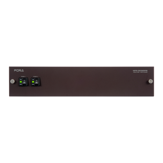
Page 56: Mfr-3232Rps
6-2-7. MFR-3232RPS (All dimensions in mm.) MFR-3232RPS ROUTING SWITCHER POWER 1 POWER 2 6-2-8. MFR-GPI (All dimensions in mm.) -
Page 57: Mfr-Talm
6-2-9. MFR-TALM (All dimensions in mm.) If attaching the rack mount brackets (Dual / Single) - Page 58 Warning This equipment has been tested and found to comply with the limits for a Class A digital device, pursuant to Part 15 of FCC Rules. These limits are designed to provide reasonable protection against harmful interference when the equipment is operated in a commercial environment. This equipment generates, uses, and can radiate radio frequency energy and, if not installed and used in accordance with the instruction manual, may cause harmful interference to radio communications.
- Page 59 2 Executive Drive, Suite 670, Fort Lee Executive Park, Fort Lee, NJ 07024, USA Tel: +1 201 944 1120 Fax: +1 201 944 1132 FOR-A Corporation of America Distribution & Service Center 2400 N.E. Waldo Road, Gainesville, FL 32609, USA Tel: +1 352 371 1505...
Need help?
Do you have a question about the MFR-1616 and is the answer not in the manual?
Questions and answers