
Related Manuals for FOR-A MFR-6100


Summary of Contents for FOR-A MFR-6100
- Page 1 OPERATION MANUAL MFR-6100 Multi Format Routing Switcher MFR-61CPU MFR-61PS MFR-9SDI12GA MFR-9SDO12GA MFR-9SDI MFR-9SDO MFR-GPI MFR-TALM Edition...
- Page 2 Precautions Important Safety Warnings [Power] Operate unit only at the specified supply voltage. Caution Disconnect the power cord via the power plug only. Do not pull on the cable portion. Do not place or drop heavy or sharp-edged objects on the power cord. A damaged cord can cause fire or electrical shock hazards.
- Page 3 [Circuitry Access] Do not remove covers, panels, casing, or access the circuitry with power applied to the unit. Turn the power off and disconnect the power cord prior to removal. Internal servicing / adjustment of unit should only be performed by qualified personnel. Do not touch any parts / circuitry with a high heat factor.
- Page 4 OpenSSL This product includes software developed by the OpenSSL Project for use in the OpenSSL Toolkit (http://www.openssl.org/) Freetype Portions of this software are copyright © 2005 The FreeType Project (www.freetype.org). All rights reserved. Lighttpd Copyright © 2004, Jan Kneschke, incremental. All rights reserved. Redistribution and use in source and binary forms, with or without modification, are permitted provided that the following conditions are met: - Redistributions of source code must retain the above copyright notice, this list of conditions and the following disclaimer.
- Page 5 Upon Receipt MFR-6100 units and their accessories are fully inspected and adjusted prior to shipment. Check your received items against the packing lists below. Check to ensure no damage has occurred during shipment. If damage has occurred, or items are missing, inform your supplier immediately.
- Page 6 Shaded text (such as ON) indicates parameter values in the menu. Text enclosed by a square (such as ALARM, MODE) indicates front panel buttons on the MFR-6100 or Remote Control Units. References to the MFR Series Web-based Control Software are indicated by [Web-based...
-
Page 7: Table Of Contents
1. Prior to Starting ............................ 9 1-1. Overview ............................ 9 1-2. Features ............................. 9 2. Panel Descriptions ..........................10 2-1. MFR-6100 Front Panel ......................10 2-1-1. Matrix Size Chart ......................11 2-2. FR-6100 Rear Panel ........................ 12 2-2-1. Interfaces .......................... 13 2-3. - Page 8 5-3-8. CPU Change-over Commands (12) ................. 56 6. Troubleshooting ..........................57 7. Specifications and Dimensions ......................58 7-1. Unit Specifications ........................58 7-1-1. MFR-6100 ......................... 58 7-1-2. MFR-GPI ........................... 59 7-1-3. MFR-TALM ........................60 7-2. External Dimensions ........................ 61 7-2-1. MFR-6100 ......................... 61 7-2-2.
-
Page 9: Prior To Starting
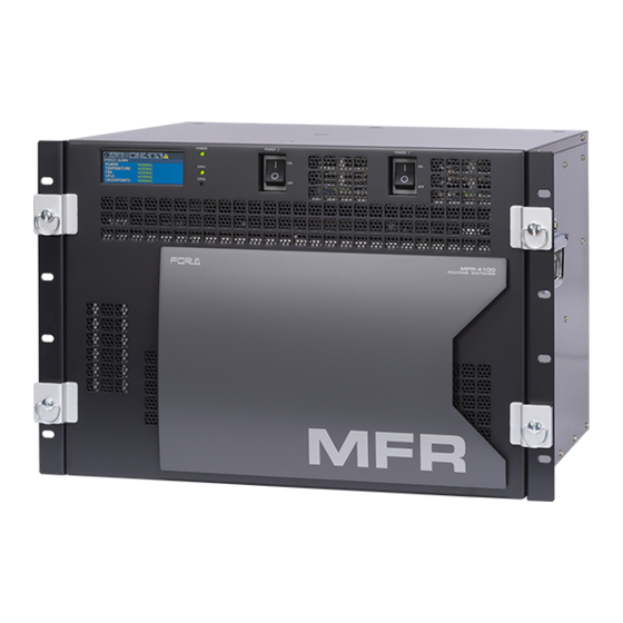
1. Prior to Starting 1-1. Overview The MFR-6100 is a multi-format routing switcher that supports 12G-SDI, 6G-SDI, 3G-SDI, HD-SDI and SD-SDI signals. Inside the 13U case a matrix of up to 144 inputs/ 144 outputs can be configured. It supports various functions such as the capability of linking multiple units, tally connections with peripheral devices, and automatic source name tracking, to allow the units to be the core product in A/V systems. -
Page 10: Panel Descriptions
2. Panel Descriptions 2-1. MFR-6100 Front Panel POW ER CPU2 CPU1 MFR-6100 ROUTING SW ITCHER POWER 1 POWER 2 Name Description POWER1 Switch used to turn unit power ON / OFF. POWER2 Switch used to power ON / OFF the optional power supply. -
Page 11: Matrix Size Chart
2-1-1. Matrix Size Chart Matrix size varies depending on the number of installed MFR-9SDI12GA, MFR-9SDI, MFR- 9SDO12GA and MFR-9SDO cards as shown below. (144 x 144 to 9 x 9) Number of cards: MFR-9SDO12GA or MFR-9SDO... -
Page 12: 6100 Rear Panel
OUTPUT INPUT 9 10 11 12 9 10 11 12 13 14 15 16 13 14 15 16 MFR-6100 *The above figure shows an MFR-6100 with MFR-9SDI12GA and MFR-9SDO12GA cards installed. Name Description MFR-LAN Ethernet ports for connection to MFR Remote Control Units and... -
Page 13: Interfaces
2-2-1. Interfaces ◆ SERIAL Connector (9-pin D-sub, male) Select RS-232C or RS-422 using the slide switch at the bottom of the connector. RS-232C Connector Pin Assignments Pin No. Signal Name Description Not used Received Data Transmitted Data Data Terminal Ready Signal Ground Data Set Ready Request to Send... - Page 14 ◆ ALARM Connector (9-pin D-sub, female) Alarm 1 Out: Normal operation: Pins 1 and 6 are open. Malfunction or power-off: Pins 1 and 6 are closed. Alarm 2 Out: Normal operation: Pins 2 and 7 are open. Malfunction or power-off: Pins 2 and 7 are closed.
-
Page 15: Sdi Input/Output Cards
MTX Power Alarm An alarm is output if power failure occurs in the matrix card. MTX FPGA Alarm An alarm is output if any failure occurs in the FPGA on the matrix card. MTX Shutdown An alarm is output if the matrix card power is turned off. 2-3. -
Page 16: Mfr-9Sdo
2-3-4. MFR-9SDO The MFR-9SDO is an SDI output card. Nine 6G/3G/HD/SD-SDI signals can be output. Set up output signals in the Web-based Control Software as shown below. ◆ Destination Name Open the [Web-based Control: ROUTER SYSTEM SETTINGS - Destination Name page]. This page allows you to change destination names displayed on Remote Controllers or other devices. -
Page 17: Rear Panel
2-4-2. Rear Panel SERIAL SERVICE MFR-LAN GPI 1 GPI 2 GPI 3 GPI 4 2 -DC12V IN- 1 Item Description Used to connect the MFR main unit MFR-LAN Ethernet port (10/100 BASE-TX) SERVICE Used for maintenance only. Do not use. DC12V IN 1, 2 Used to supply 12V DC power. -
Page 18: Interfaces (Mfr-Gpi)
2-4-3. Interfaces (MFR-GPI) ◆ GPI IN / TALLY OUT Connector (37-pin D-sub, female) 37 36 35 34 33 32 Pin No. Signal Pin No. Signal GPI_IN / TALLY_OUT 01 # GPI_IN / TALLY_OUT 20 # GPI_IN / TALLY_OUT 02 # GPI_IN / TALLY_OUT 21 # GPI_IN / TALLY_OUT 03 # GPI_IN / TALLY_OUT 22 #... - Page 19 GPI OUT / TALLY OUT Circuit MFR-GPI External device Max. voltage: 40V Max. Current: 100mA 10Ω Approx. 0.9V when turned-on...
-
Page 20: Card Switches
Further note that adjustments and maintenance should only be performed CAUTION by qualified technical personnel familiar with FOR-A equipment. Remove the two screws on both sides of the MFR-GPI to access the internal card as shown below. The figure below shows the factory default switch settings. -
Page 21: Mfr-Talm
2-5. MFR-TALM 2-5-1. Front Panel ITEM Description Displays power status. POWER ► See the table below for details on indications. Displays the flash memory writing status of backup settings. BUSY ► See the table below for details on indications. REF IN Lights green when an external reference signal is present. -
Page 22: Rear Panel
2-5-2. Rear Panel ITEM Description Ethernet port for connection to PC or other external unit PC-LAN (10/100BASE-TX, RJ-45) Ethernet port for connection to MFR main unit MFR-LAN (10/100/1000BASE-T, RJ-45) Used to input a reference signal (BB or Tri-level sync signal) REF IN (with loop-through. -
Page 23: System Configuration Example
The block diagram below shows an example of the basic MFR routing system that consists of an MFR-6100, Remote Unit and the Web-based Control accessed from a computer. Make sure to connect both MFR-LANs (CPU1) and (CPU2) to a LAN respectively for CPU redundancy. -
Page 24: Main Unit Linking
Synchronous control of one MFR-6100 and one MFR-6000 IP address and SNMP settings should be performed on each MFR-6100 unit. After these settings are completed, all linked MFR-6100 units are set and controlled together on the unit that is specified as Master. -
Page 25: Configuring The System With Mfr-Talm
Connect all devices in the MFR system as shown in the figure above. Power on the MFR-6100 to be set as a Master, Remote Control unit and PC. Set the IP addresses for the Remote Control unit (1) and PC (4). Power off the Master MFR-6100. - Page 26 ◆ Transmitting Signal Name and Tally Data The figure below shows an example signal name and tally data routing system using the MFR- TALM. MFR-6100 MFR- MFR- Video Switcher 9SDI12GA 9SDO12GA (HVS-2000) OUT1 RS-422(1) RS-422(4) IN144 OUT144 MFR-LAN PC-LAN Multi Viewer...
- Page 27 TCP/IP Setting Open the [MFR-TALM Web-based Control: Port Settings page] and perform port settings under TCP/IP Port. [Port Settings] - [TCP/IP Port] Port Menu Access IP Address Port Function Method Web-based Control (MV TCP/IP TSL UMD protocol Client port number) IP address) V5.0 Tally out [TALM Settings]...
-
Page 28: Switcher's Aux Crosspoints Switching System
Assume that the system is configured as shown below: AUX1 on the switcher is assigned to DST 201 (Level 1) on the MFR-6100. IN1-8 on the switcher are assigned to SRC201-208 on the MFR-6100 and STL (Still) 3 is assigned to SRC209. - Page 29 Connect and assign video signals as shown in the figure on previous page. Device Setup on the MFR-6100: Connect to the MFR-6100 from the Web-based Control PC and open the [Tally System Settings - Device Select] page. Select HVS-390HS in the [Switcher] field and click [Send].
-
Page 30: Synchronous Crosspoints Switching
Assign IN1 to SRC 201. After above setup settings are complete: If SRC 201 is selected for DST 201 on the MFR-6100, IN1 is selected for AUX1 on the switcher. If SRC 3 is selected for DST 201 on the MFR-6100, IN9 is selected for AUX1 on the switcher and SRC 3 is also selected for DST 112 on the MFR-6100. -
Page 31: Redundant Cpu Configuration
3-5. Redundant CPU Configuration A secondary CPU can be installed on an MFR-6100 to configure CPU redundancy. An active CPU controls the system and the other CPU monitors the system. The CPU usage state (which CPU is active) can be checked by monitoring through Status Indicators on the front panel, Menu Display or Web-based Control. -
Page 32: Menu Display Operation
4. Menu Display Operation Unfasten four fixing screws on the front panel and POW ER CPU2 CPU1 detach the front panel. MFR-6100 ROUTING SW ITCHER POWER 1 Removing the front panel reveals menu display operation buttons. POWER 2 CONTROL Button... -
Page 33: Status
Reboot is required to apply setting. IMPORTANT Check items listed below when WARNING is displayed. - Are ventilation opening on MFR-6100 secured? - Is the ambient temperature within the operating temperature range? - Is the AC input voltage appropriate? 4-1-1. STATUS > INFO... -
Page 34: Status > Mfr-Lan
4-1-2. STATUS > MFR-LAN Displays MFR-LAN CPU1 and CPU2 IP and Subnet mask addresses. 4-1-3. STATUS > PC-LAN Displays PC-LAN CPU1 and CPU2 IP, Subnet mask and Gateway addresses. 4-1-4. STATUS > SLOT Move into [STATUS > SLOT] menu where a slot can be selected by pressing CONTROL. Select a slot by turning CONTROL to decide a slot to display the installed card information. -
Page 35: Status > Power
4-1-5. STATUS > POWER Displays power supply status for each card and power supply unit. Item Description CPU1 NORMAL: Normal CPU2 ERROR: Abnormal (*1) MATRIX1 (*1) MATRIX2 (*1) If MATRIX1 or MATRIX2 card has an error, turn off the FRONT card. -
Page 36: Status > Fan
4-1-7. STATUS > FAN Status of MFR-6100 rear fan (REAR 1-6) and power supply fan (PS1-2) units. Item Description REAR 1-6 NORMAL: Normal WARNING: Warning PS1-2 ERROR: Fan error 4-1-8. STATUS > VERSION Displays FW (Firmware), FPGA and CPLD versions for each card. -
Page 37: Setting
4-2. SETTING Turn CONTROL to select a menu to change settings and press CONTROL to enter the settings screen. Menu Description SWAP ACTIVE CPU Allows you to verify CPU condition and manually swap the active CPU. SLOT SHUTDOWN Allows you to turn on/off an in/out card. POWER SUPPLY 2 Allows you to verify power supply 2 installation and change settings. -
Page 38: Turning On/Off An Input/ Output Card
4-2-2. Turning ON/OFF an Input/ Output Card Example) Turning OFF the INPUT1 slot. Open the [SETTING > SLOT SHUTDOWN] menu. Turn and press CONTROL to select INPUT1 in TARGET SLOT. Turn press CONTROL select EXECUTE in CHANGE STATE. A Now Executing…... -
Page 39: Changing Menu Display Settings
4-2-4. Changing Menu Display Settings Open the [SETTING > FRONT DISPLAY] menu to change MFR-6100 menu display settings. When the menu is not displayed, press the CANCEL button to display the menu. Changing Menu Display Brightness Open the [SETTING > FRONT DISPLAY] menu. -
Page 40: Power Off For Matrix Card
4-2-5. Power Off for Matrix Card If any failure occurs in a matrix card, turn off the card to protect it. When the matrix card is turned off, no image outputs. To turn on the matrix card, restart the main unit. If a serious failure occurs in the matrix card, it is automatically powered off. -
Page 41: Serial / Lan Command Control
Login password None Communication protocol TCP/IP, Control PC: Client, MFR-6100: Server Crosspoint Remote Control using ASCII code. Command protocol Crosspoint Remote Control protocol When a redundant CPU is configured, a client should connect to both LAN ports (PC-LAN CPU1 and PC-LAN CPU2) and send commands to the ports respectively. -
Page 42: Control Commands
5-3. Control Commands Although the protocols listed below support both serial and LAN connections, some commands can only be sent over a LAN. ◆ Control command list Function Serial LAN *1 Protocol *2 Commands (S?) for requesting the crosspoints list Commands (X?) for requesting information on crosspoints (by specifying a destination and level.) Commands (X:) for switching over a crosspoint (single... -
Page 43: Command Responses (Commands 1-6)
@[sp]A? If CPU is active: A:<ID> 5-3-4 If CPU is passive: (No response) @[sp]W?<Lvl>,<Dest> W!<Lvl><Dest>,<ID>,0-2 5-3-5 K:<S or D><S or L or A><No.>,<Dat> 5-3-6 Sets video format (reference and/or UF!<YY>/<R#>,<S$> 5-3-7 switching point) settings. @[sp]UF:<YY>/<R#>,<S$> Performs the settings. UR!W UR!<YY>/<R#>,<S$> @[sp]UE:A UR!E(Error response) Cancels the settings. - Page 44 “C” responses A “C” response is sent as shown below when a control command is received: [CR][LF]C:<Lvls>/<Dest>,<Src>[…[S<Salvo number>][L<Link number>]]:I<ID>[CR][LF] * C responses are sent to all terminals in the system. Parameter Setting range Description <Salvo number> 1-FFF The number of crosspoints to be changed simultaneously by Salvo settings.
-
Page 45: Receiving Responses (Commands 1-6)
5-3-2. Receiving Responses (Commands 1-6) Timeout Period for Response Commands from MFR Set the timeout period (maximum permitted time until its response returns from the MFR unit) to 1 second for short message commands and to 5 seconds for long message commands. For CPU changeover commands, set the timeout period to 15 seconds. - Page 46 Response Message Evaluation Example: Response message received New line? [CR] or [LF] Prompt? Is the 1st character of a line Prompt? - Prompts are not added to line buffers. Add to line buffer Processing S Response Does the line buffer begin with S:? - Other characters are recognized and used as tallies.
- Page 47 If Commands Overlap: Two or more commands are sent from different terminals (via serial or LAN interface, or Remote Control units), all command results (C and S responses) are returned to all these terminals from the MFR. The following command examples show how overlapped commands are processed. Ex.) Assume that the following commands are overlapped: Terminal 1 sent “@ X:0/2,4.”...
-
Page 48: Channel Name Request Commands (7)
5-3-3. Channel Name Request Commands (7) K? commands allow you to obtain Source and Destination names in ASCII and/or in Kanji set in the MFR Web-based Control menu. ◆ Command Format Command Command response @[sp]K?<S or D><A or K>,<Offset> K:<SorD><AorK><No.>,<Dat> BYTE No. - Page 49 ◆ Command Example 1: Requesting the Source Channel 1 Ascii Name ➢ Web-based Control (Source Name menu) ➢ Terminal display Command @ K?SA,000 Response @ K?SA,000 Echo K:SA000,5352432031 Ascii Name for Source Channel 1 is SRC 1. K:SA001,5352432032 Ascii Name for Source Channel 2 is SRC 2. K:SA002,5352432033 Ascii Name for Source Channel 3 is SRC 3.
- Page 50 ◆ Command Example 2: Requesting the Destination Channel 101 Kanji Name ➢ Web-based Control (Destination Name menu) ➢ Terminal display Command @ K?DK,064 Response @ K?DK,064 Echo K:DK064,E587BAE58A9BEFBC91EFBC90EFBC91 Kanji Name for Destination Channel 101 is 出力101. K:DK065,E587BAE58A9BEFBC91EFBC90EFBC92 Kanji Name for Destination Channel 102 is 出力102.
- Page 51 ◆ Command Example 3: Requesting the Source Channel 65 Kanji Name ➢ Web-based Control (Source Name menu) ➢ Terminal display Command @ K?SK,040 Response @ K?SK,040 Echo K:SK040,E382ABE383A1E383A9EFBC91 Kanji Name for Source Channel 65 is カメラ1. K:SK041,E382ABE383A1E383A9EFBC92 Kanji Name for Source Channel 66 is カメラ2.
-
Page 52: Cpu Status Request Command (8)
サ ― バ ― A Source Kanji Channel 72 5-3-4. CPU Status Request Command (8) This command allows you to indicate which CPU is active in the MFR-6100. ◆ Command format Command Command response @[sp]A? A:<ID> BYTE No. Command [sp] BYTE No. -
Page 53: Destination Lock Status Request Command (9)
5-3-5. Destination Lock Status Request Command (9) This command (W?) allows you to indicate destination lock status in the MFR system. ◆ Command format Control command Command response @[sp]W?<Lvl>,<Dest> W!<Lvl><Dest>,<ID>,0-2 Control command BYTE No. Command [sp] <Lvl> <Dest> <Dest>: Destination channel number Command response BYTE No. -
Page 54: Channel Name Import Commands (10)
5-3-6. Channel Name Import Commands (10) K: commands allow you to import Source and Destination names from the device that sends K: commands to the MFR system. ◆ Command Format Command Command response K:<S or D><S or L or A><No>,<Dat> Echo Prompt BYTE No. - Page 55 <YY> Video format 00: 1080/59.94i 07:720/59.94p 0E: 1080/30psF 01: 1080/59.94p 08:720/50p 0F: 1080/29.97psF 02: 1080/60i 09: 1080/30p 10: 1080/25psF 03: 1080/60p 0A: 1080/29.97p 11: 1080/24psF 04: 1080/50i 0B: 1080/25p 12: 1080/23.98psF 05: 1080/50p 0C: 1080/24p 13: 525/59.94i 06:720/60p 0D: 1080/23.98p 14: 625/50i <R#>...
-
Page 56: Cpu Change-Over Commands (12)
5-3-8. CPU Change-over Commands (12) CPU Change-over (CPU Swap) commands allow you to swap the active CPU. Available only when CPU2 is passive. Switches the active CPU from CPU1 to CPU2. This command should be sent to CPU2. ◆ Command Format Command description Command Command response... -
Page 57: Troubleshooting
6. Troubleshooting If any of the following problems occur while operating your MFR-6100, proceed as indicated below to see if the problem can be corrected before assuming a unit malfunction has occurred. IMPORTANT If the problem cannot be corrected by performing the procedures below, turn the unit off and then on again. -
Page 58: Specifications And Dimensions
7. Specifications and Dimensions 7-1. Unit Specifications 7-1-1. MFR-6100 Basic specifications Temperature / Humidity 0ºC to 40ºC / 30% to 85% (no condensation) Power 100 VAC to 240 VAC ±10%, 50/60Hz IN Consumption SDI 144 x 144, Dual CPU/Redundant Power Unit (Maximum... -
Page 59: Mfr-Gpi
When MFR-9SDI12GA and MFR-9SDO12GA cards are installed. Process Delay 12G-SDI: Less than 1.0 µs 6G-SDI: Less than 1.0 µs 3G-SDI: Less than 1.0 µs HD-SDI: Less than 1.5 µs SD-SDI: Less than 3.0 µs When MFR-9SDI and MFR-9SDO12GA cards are installed. When MFR-9SDI12GA and MFR-9SDO cards are installed. -
Page 60: Mfr-Talm
7-1-3. MFR-TALM Basic specifications Temperature / Humidity 0ºC to 40ºC / 30% to 85% (no condensation) Power +12VDC pin connector x 2 (redundant power supply as standard) Consumption 100 V AC to 120 V AC: 17 VA (9 W), 200 V AC to 240 V AC: 20 VA (9 W) Dimensions 212(W) x 44(H) x 161(D) mm EIA 1 RU Half Rack 480 (W) (Including single or dual rack mount brackets) -
Page 61: External Dimensions
7-2. External Dimensions 7-2-1. MFR-6100 (All dimensions in mm.) FAN 5 FAN 6 RE F IN CPU2 CP U1 ALA RM MFR-LAN PC-LAN MFR-LAN PC-LAN 232C SER IAL INP UT OUT PUT INP UT POW ER CP U2 CP U1... -
Page 62: Mfr-Talm
7-2-3. MFR-TALM (All dimensions in mm.) ◆ If attaching the rack mount brackets (Dual / Single) - Page 63 Warning This equipment has been tested and found to comply with the limits for a Class A digital device, pursuant to Part 15 of FCC Rules. These limits are designed to provide reasonable protection against harmful interference when the equipment is operated in a commercial environment. This equipment generates, uses, and can radiate radio frequency energy and, if not installed and used in accordance with the instruction manual, may cause harmful interference to radio communications.
- Page 64 Tel: +1 352-371-1505 Fax: +1 714-894-5399 FOR-A Latin America and the Caribbean Miami Office Tel: +1 657-600-5759 FOR-A Latin America and the Caribbean Sao Paulo Office Tel: +55 (0)11-99913-3751 FOR-A Europe S.r.l. Via Volturno, 37, 20861 Brugherio MB, Italy Tel: +39 039-916-4811...
Need help?
Do you have a question about the MFR-6100 and is the answer not in the manual?
Questions and answers